Effective Hydrodynamic Boundary Conditions for Microtextured Surfaces
Abstract
Understanding the influence of topographic heterogeneities on liquid flows has become an important issue with the development of microfluidic systems, and more generally for the manipulation of liquids at the small scale. Most studies of the boundary flow past such surfaces have concerned poorly wetting liquids for which the topography acts to generate superhydrophobic slip. Here we focus on topographically patterned but chemically homogeneous surfaces, and measure a drag force on a sphere approaching a plane decorated with lyophilic microscopic grooves. A significant decrease in the force compared with predicted even for a superhydrophobic surface is observed. To quantify the force we use the effective no-slip boundary condition, which is applied at the imaginary smooth homogeneous isotropic surface located at an intermediate position between top and bottom of grooves. We relate its location to a surface topology by a simple, but accurate analytical formula. Since groves represent the most anisotropic surface, our conclusions are valid for any texture, and suggest rules for the rational design of topographically patterned surfaces to generate desired drag.
pacs:
68.08.-p, 68.35.CtIntroduction.– The advent of microfluidics has motivated the growing interest in understanding and modeling of flows at small scales or in tiny channels. In recent years it has become clear that the no-slip boundary condition at a solid-liquid interface is valid only for smooth hydrophilic surfaces Vinogradova and Yakubov (2003); Cottin-Bizonne et al. (2005); Joly et al. (2006); Vinogradova et al. (2009), and for many other systems it does not apply when the size of a system is reduced. Thus the hydrophobicity of smooth surfaces could induce a partial slippage, where is the velocity at the wall, the slip length, and the axis is normal to the surface Vinogradova (1999). This concept is now well supported by nanorheology measurements Cottin-Bizonne et al. (2005); Vinogradova and Yakubov (2003); Vinogradova et al. (2009).
However, only very few solids are molecularly smooth. Most of them are rough, often at a micrometer scale. This roughness may be induced by some processes of fabrication or coating, but microtextures are also found on the surfaces of most plants and animals. In particular, many solids are naturally striated by grooves, which can also be prepared for specific microfluidic purposes, such as passive chaotic mixing Stroock et al. (2002); Feuillebois et al. (2010). Most studies of flow past rough surfaces have concerned poorly wetting liquids for which the topography acts to favor the formation of trapped gas bubbles (Cassie state), and to generate superhydrophobic slippage Rothstein (2010); Vinogradova and Belyaev (2011). For rough wettable surfaces the situation is unclear, and opposite conclusions have been made: one is that roughness generates extremely large slip Bonaccurso et al. (2003), and one is that it decreases the degree of slippage Zhu and Granick (2002). Recent data (supported by simulations Kunert et al. (2010)) suggest that the description of flow near rough surfaces has to be corrected, but rather for a separation, but not slip Vinogradova and Yakubov (2006); Steinberger et al. (2007). Another suggestion is to combine these two models Guriyanova et al. (2010).
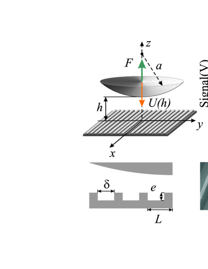
In this Letter we describe how the boundary conditions can be modified by the surface texture. We focus on the case of special interest where this model surface is decorated by rectangular microgrooves, i.e. on the situation of the largest possible anisotropy of the flow. We analyze the hydrodynamic interaction between a smooth sphere and a grooved plane, as sketched in Fig. 1, and the texture parameters are systematically varied at the micrometer level, in order to investigate their influence on a drag force. Our results do not support some previous experimental conclusions on a large slip for similar systems. Instead, we unambiguously prove the concept of an effective no-slip plane shifted down from the top of roughness. To the best of our knowledge, this is the first study, where experimentally found values of this shift were quantified theoretically and related analytically to controlled parameters of topographic patterns.
Experimental.– We use a specially designed homemade setup Lecoq et al. (1993, 2004); Mongruel et al. (2010) to measure on a microscale the displacement of a sphere towards the corrugated wall at constant gravity force. The steel sphere of density kg m-3 and radii ranging from mm to mm is embedded in a liquid contained in a cylindrical glass vessel with a mm diameter and a mm height. As a liquid we have chosen high molecular weight PDMS (silicone) oil (47V100000 Rhodorsyl oil, from Rhone-Poulenc.), with dynamic viscosity Pa s at C, which is Newtonian for shear rates up to s-1. Such shear rates are never reached in our experiment.
Table 1 : Parameters of the textured samples and the shift of effective hydrodynamic wall, . , expe- , theory riment, [Eqs.(4), (6), (7)], (m) (m) (m) (m) (m) 1 100 50 1/2 45 5 0.1 5.5 2 150 50 1/3 45 4.2 0.3 3.5 3 150 100 2/3 45 13 2 11.8 4 200 100 1/2 76 13 3 10.4 5 200 100 1/2 45 9 1.5 8.3 6 250 25 1/10 42 0.5 0.1 0.6 7 250 225 9/10 42 28.5 0.5 23.5
The microstructured surfaces were created by common soft lithography, in a three steps process, transferring geometric shapes from a mask: first to a silicon wafer coated with a (SU8) photoresist, second to a replica molding obtained by soft imprint of a thermo-reticulable PDMS, and finally to a replica of the PDMS mold by soft imprint of a thiolene based resin (NOA 81, Norland optical adhesives) on glass microscope slides (to be fixed at the bottom of the vessel). This resin was chosen for its resistance to compression and to solvent-swelling, and for its good adhesion to glass Bartolo et al. (2008). The final structures are checked by scanning electron microscopy (see Fig. 1). The textures are characterized by spacing , height and period . The liquid fraction, can be precisely measured since it is the ratio of the upper surface of the crenellations over the total surface of the sample. It varies largely with the patterns (from 0.1 to 0.9), and varies from 0.168 to 0.45, as displayed in Table 1. Contact angles against PDMS for all textures were found to be below so that surfaces can be considered as lyophilic. Therefore, we expect PDMS to invade the surface texture (Wenzel state).
We measure the distance, which is defined from the top of the textures (contact) by using an interferometric technique Lecoq et al. (1993, 2004); Mongruel et al. (2010) with the accuracy 0.2 m. The velocity of the sphere is found by multiplying the velocity of interference fringes displacement by a factor of where nm is the wavelength of the He-Ne laser, and the refraction index of PDMS. After opto-electronic conversion and amplification, the signal is recorded with a high frequency electronic oscilloscope (DPO4032 from Tektronics). A deceleration of the sphere (Fig. 1) is reflected in the increase of the period of the signal, until contact occurs, and its position is defined from the recorded signal, at the time when the period of the signal becomes very large indicating a vanishing velocity. Note that the signal-to-noise ratio deteriorates at vanishing frequency, because the low frequency limit of the oscilloscope is reached. The measured frequency is averaged over to periods, except just before the contact, where no averaging is applied in order to capture the rapid velocity variations occurring in that region.
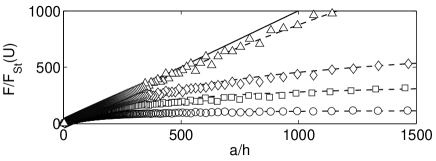
Results and discussion.– Fig. 2 shows the drag (equal to the gravity force) scaled by the Stokes force , i.e. . Solid line is a theoretical force (Taylor’s equation) predicted for a case of smooth wall and no slippage at the surface:
| (1) |
Also included are the experimental data for samples with similar , but different and , which show deviations from the behavior predicted by Eq. 1. Close to the wall, for , the drag is always significantly less than the force near a smooth wall, and this reduction increases with .
To examine these deviations we evaluate a correction to the drag force,
| (2) |
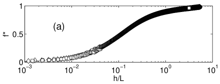
Note that in general case for a rough surface should also depend on the radius of the sphere Kunert et al. (2010). However, with our configuration geometry experimental data do not vary with . This is well illustrated in Fig. 3(a), where the experimental values of obtained with sample #7 at different and plotted as a function of collapse into a single curve, which tends to unity at large distances and decreases significantly when becomes of the order of and smaller. Since at short separations we observe , one can conclude that slippage (which would lead to Vinogradova (1995)) obviously does not mimic roughness when is small, by overestimating the drag force. The same remark concerns effective superhydrophobic slippage where Asmolov et al. (2011) and is equal to for this particular sample.
Therefore, our experimental results are now compared with theoretical calculations made for an effective smooth plane shifted down from the top of the corrugations, i.e. by assuming where is the value of constant, i.e. independent on , shift. This implies that
| (3) |
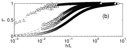
Fig. 3(a) includes a calculation (dashed curve) in which an adjustable parameter, a shift of m, is incorporated into the Taylor equation. The fit is very good for all , suggesting the validity of the model. Fig. 3(b) shows another series of experiments made with the fixed radius of the sphere, but different parameters of the texture. If similar fits are made to a variety of experiments it is found that the shift of an equivalent plane required to fit each run increases from 0.5 m for sample #2 to 28.5 m for sample #7. In Table 1 we present the experimental values of for different samples, and theoretical curves calculated with Eq.(3) are included in Figs. 2 and 3. The fit is excellent at all separations except as very small, . Thus our experiment shows that an effective (scalar) shift, , is a unique physical parameter that fully quantifies drag reduction at a highly anisotropic corrugated surface. This striking result indicates that in our experiment pressure remains isotropic despite an anisotropy of the flow.
Now we try to relate to parameters of textured surfaces. As proven in Lecoq et al. (2004); Asmolov et al. (2011), for a large gap, , the shift of the equivalent no-slip plane from the real surface is equal to the average of the eigenvalues of the effective slip-length tensor (at the slip plane defined at the top of asperities)
| (4) |
Therefore, the problem of calculating reduces to computing the two far-field eigenvalues, and , which attain the maximal and minimal directional slip lengths, respectively.
In the limit the theory Kamrin et al. (2010) predicts that the effective no-slip surface for arbitrary smooth periodic surfaces is at the average height:
| (5) |
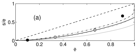
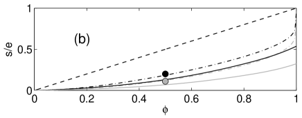
so that is controlled mainly by . To examine the significance of more closely, the experimental normalized by are reproduced in Fig. 4. The measured data show much smaller than the theoretical prediction of model (5) shown by a dashed line. A possible explanation for this discrepancy is that the height of asperities in our experiments was not small enough, We also compared our data with another calculation (solid curves) for hydrophilic grooves with finite based on numerical results Wang (2003) for eigenvalues of the slip-length-tensor. Even at moderate theoretical predictions for Wang (2003) are much smaller than measured values.
An alternative model can be obtained if we use the analytic solutions for alternating slip and no-slip stripes Belyaev and Vinogradova (2010):
| (6) |
| (7) |
where we naturally assumed that the local partial slip is equal to the height of grooves. Fig. 4 shows that Eq. (4) together with Eqs. (6) and (7) (dashed curves) give almost quantitative agreement with experimental data. (We also include theoretical values of to Table 1 to allow a direct comparison with experimental results.) Therefore, by using the equivalence of a flow past rough and heterogeneous surfaces at large scale, we were able to quantify a drag reduction at the smaller scale, of the order of the size of roughness elements. Note however that our results do not apply to a very thin gap situation where scales with the channel width epa , which is again consistent with our experiment.
Concluding remarks.– We have studied a drag force on a sphere approaching a corrugated plane. Our experiment shows quantitatively that in this situation the effective no-slip boundary condition, which is applied at the imaginary smooth homogeneous isotropic surface located at an intermediate position between top and bottom of grooves, fully mimics the actual one along the true corrugated interface, except as for a very thin gap. The location of this effective isotropic plane depends on the parameters of the texture, and can be found by using simple formulae for effective slip lengths in the limit of a thick channel. Since for grooves anisotropy is maximized, the same conclusion would be valid for other types of anisotropic (e.g., sinusoidal, trapezoidal, and more) and/or isotropic (e.g. pillars, etc) textures, but of course, Eqs. (6) and (7) should be replaced by analytical or numerical solutions for a corresponding texture, as will be described in subsequent papers.
We have also demonstrated that topographically patterned (Wenzel) surfaces could reduce a drag force more efficiently compared to expected even for slipping superhydrophobic (Cassie) textures with trapped gas. Therefore, our results suggested rules and a general strategy for the rational design of topographically patterned surfaces to generate desired low drag.
References
- Vinogradova and Yakubov (2003) O. I. Vinogradova and G. E. Yakubov, Langmuir 19, 1227 (2003).
- Cottin-Bizonne et al. (2005) C. Cottin-Bizonne, B. Cross, A. Steinberger, and E. Charlaix, Phys. Rev. Lett. 94, 056102 (2005).
- Joly et al. (2006) L. Joly, C. Ybert, and L. Bocquet, Phys. Rev. Lett. 96, 046101 (2006).
- Vinogradova et al. (2009) O. I. Vinogradova, K. Koynov, A. Best, and F. Feuillebois, Phys. Rev. Lett. 102, 118302 (2009).
- Vinogradova (1999) O. I. Vinogradova, Int. J. Mineral Proces. 56, 31 (1999).
- Stroock et al. (2002) A. D. Stroock, S. K. W. Dertinger, A. Ajdari, I. Mezić, H. A. Stone, and G. M. Whitesides, Science 295, 647 (2002).
- Feuillebois et al. (2010) F. Feuillebois, M. Z. Bazant, and O. I. Vinogradova, Phys. Rev. E 82, 055301(R) (2010).
- Rothstein (2010) J. P. Rothstein, Ann. Rev. Fluid Mech. 42, 89 (2010).
- Vinogradova and Belyaev (2011) O. I. Vinogradova and A. V. Belyaev, J. Phys.: Condens. Matter 23, 184104 (2011).
- Bonaccurso et al. (2003) E. Bonaccurso, H.-J. Butt, and V. S. J. Craig, Phys. Rev. Lett. 90, 144501 (2003).
- Zhu and Granick (2002) Y. Zhu and S. Granick, Phys. Rev. Lett. 88, 106102 (2002).
- Kunert et al. (2010) C. Kunert, J. Harting, and O. I. Vinogradova, Phys. Rev. Lett 105, 016001 (2010).
- Vinogradova and Yakubov (2006) O. I. Vinogradova and G. E. Yakubov, Phys. Rev. E 73, 045302(R) (2006).
- Steinberger et al. (2007) A. Steinberger, C. Cottin-Bizonne, P. Kleimann, and E. Charlaix, Nature Mater. 6, 665 (2007).
- Guriyanova et al. (2010) S. Guriyanova, B. Semin, T. S. Rodrigues, H. J. Butt, and E. Bonaccurso, Microfluid Nanofluid 8, 653 (2010).
- Lecoq et al. (1993) N. Lecoq, F. Feuillebois, N. Anthore, R. Anthore, F. Bostel, and C. Petipas, Phys. Fluids 5, 3 (1993).
- Lecoq et al. (2004) N. Lecoq, R. Anthore, B. Cichocki, P. Szymczak, and F. Feuillebois, J. Fluid Mech. 513, 247 (2004).
- Mongruel et al. (2010) A. Mongruel, C. Lamriben, S. Yahiaoui, and F. Feuillebois, J. Fluid Mech. 661, 229 (2010).
- Bartolo et al. (2008) D. Bartolo, G. Degre, P. Nghe, and V. Struder, Lab. Chip 8, 274 (2008).
- Vinogradova (1995) O. I. Vinogradova, Langmuir 11, 2213 (1995).
- Asmolov et al. (2011) E. S. Asmolov, A. V. Belyaev, and O. I. Vinogradova, Phys. Rev. E 84, 026330 (2011).
- Wang (2003) C. Y. Wang, Phys. Fluids 15, 1114 (2003).
- Kamrin et al. (2010) K. Kamrin, M. Z. Bazant, and H. A. Stone, J. Fluid Mech. 658, 409 (2010).
- Belyaev and Vinogradova (2010) A. V. Belyaev and O. I. Vinogradova, J. Fluid Mech. 652, 489 (2010).
- (25) See Supplemental Material at [URL will be inserted by publisher] for details of the theoretical solution for a thin channel situation.