Nonlinear self-flipping of polarization states in asymmetric waveguides
Abstract
Waveguides of subwavelength dimensions with asymmetric geometries, such as rib waveguides, can display nonlinear polarization effects in which the nonlinear phase difference dominates the linear contribution, provided the birefringence is sufficiently small. We demonstrate that self-flipping polarization states can appear in such rib waveguides at low (mW) power levels. We describe an optical power limiting device with optimized rib waveguide parameters that can operate at low powers with switching properties.
I Introduction
Nonlinear interactions between the two polarization modes of a waveguide lead to intriguing physical effects and opportunities for new devices for optical data processing [1]-[4]. We show here how nonlinear interactions of this form can be employed to develop all-optical devices at low power levels, using switching (bistable) properties of the polarization phase difference, as described in [5], at zero birefringence wavelength in subwavelength rib waveguides. In general, the interaction between the two polarizations in an optical waveguide is described by the coupled Schrödinger equations [4]:
| (1) | |||||
where index the two polarization modes, are the amplitudes of the corresponding fields, are the th order propagation constants, is the linear birefringence, and are the effective nonlinear coefficients representing self phase modulation, cross phase modulation and coherent coupling of the two polarization modes, respectively.
The weak guidance approximation assumes that the effective mode areas of the two polarization modes are equal [4], leading to . We have shown in [5, 6] that these equalities are not necessarily valid for waveguides with large index contrast and subwavelength dimensions. For such cases a new class of time-independent polarization states appear, in which the phase difference between the two polarizations oscillates abruptly between two well-defined values, which we refer to as switching (bistable) behavior [5]. Associated with this, the polarization state of the propagating mode flips abruptly through fixed angles. This is the result of competition between the linear and nonlinear phase differences of the two polarization modes propagating along the waveguide. While the linear phase difference is proportional to (where ), the nonlinear phase difference at any point along the waveguide depends on the values and on the power coupled into each polarization. As a result, one expects that significant nonlinear polarization effects should be observed as approaches zero, i.e. when the linear phase difference is negligible. In waveguides with highly symmetric geometries, however, we have only if there is also a symmetry between the polarization mode distributions (for example, in waveguides with circular or square cross sections), in which case the nonlinear phase difference also approaches zero for the same power coupled into the two polarizations. For this reason, we previously found polarization switching only for powers at the kW level [5].
II Rib waveguides
Here, we consider rib waveguides with structural dimensions chosen such that the birefringence is nearly zero at the operating wavelength of 1550nm, following [7]-[9]. For such cases, the waveguides are polarization independent i.e., . Previous studies have identified the relation between the width and the height (etch depth) of the rib for independent polarization operation of rib waveguides [7, 9] and have used them in applications such as ring resonators [8]. For these waveguides, the mode field distributions for the two polarizations are not identical, which leads to . Therefore, the nonlinear phase difference is large relative to the linear contribution, and leads to switching behavior at power levels several orders of magnitude lower than before [5]. Hence, we are able to demonstrate polarization self-flipping through at just mW powers. This approach produces polarization states which flip under their own power, whereas in [2, 3] a second pump is required.
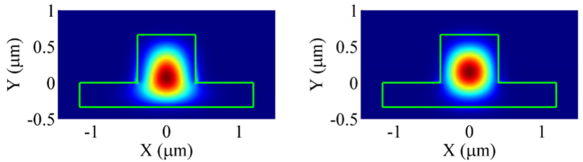
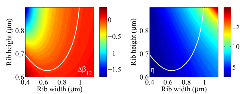
An example of mode field distributions for two polarizations with is shown in Fig. 1, for a chalcogenide glass-based rib waveguide. Evidently the distributions for the two polarizations are not identical, which leads to . These profiles have been calculated using a finite element package, and the values have been determined using the formulas (3) in [5]. The birefringence can be calculated as a function of the rib width and rib height (i.e. etch depth), and is plotted in Fig. 2, where the white line indicates points for which .
We now investigate nonlinear polarization as described in [5, 6], for waveguides with (near the white line in Fig. 2, left). We substitute for into Eqs. (1), where is the power of the field with phase and look for time-independent solutions. The total power is constant in . We define the following dimensionless variables:
| (2) | |||||
| (3) |
where is the phase difference between the two fields. From Eqs. (1) we obtain a system of equations for (see Eqs. (5,6) in [5]) which can be solved for any given at the initial location (with ), either analytically, or numerically for any specified values of . There are three types of solutions: steady state solutions, periodic (including switching) solutions, and soliton solutions. For periodic solutions the dimensionless period of (regarded as functions of ) depends only on and on . Hence, the functions are periodic in with a period , as follows from the definition of in Eq. (2). The switching behavior discussed in [5, 6] requires which from the definitions (3) implies that
| (4) |
This inequality is satisfied at relatively low powers provided is sufficiently small.
Let be the length of the waveguide, hence . We are interested in exploring the possible values of at the endpoint , i.e. at ; each depend nontrivially on the total power , regarded as a variable parameter, through . One can in principle determine the explicit dependence of on with the help of the exact solutions, but for waveguides with , however, both parameters are fixed and in this case enters the defining dimensioned equations as a scale factor only. This means that the periodic functions and their period are determined entirely by the values of the coefficients, together with the initial values . The functions at can therefore be stretched or compressed by varying either or , in particular at may be regarded as a function of either or and, since , is periodic in both and . The corresponding periods and of , of dimension length and power respectively, are given by
| (5) |
where the dimensionless period is independent of both . These simple dependencies, a consequence of the scaling properties, are useful for the application outlined below.
We consider now light that is initially linearly polarized, i.e. with equal power coupled into the two polarizations, hence . As an example, as explained further below, we choose a rib width of nm and a rib height (i.e. etch depth) of nm, with a substrate width of nm and a height of nm. We find, in units of (W.m)-1: , with numerical values for such that m-1. With mW input power and a m long waveguide, the nonlinear phase change is more than 200 times larger than the linear contribution.
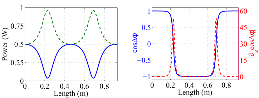
With these values we have , and so is satisfied, and therefore switching states exist. Fig. 3 shows as functions of at W. Evidently is constant, and each have the period m; displays switching by flipping between with a period m.
We optimize the rib waveguide parameters by choosing values that result not only in , but also such that flips as abruptly as possible between , relative to the period. In order to quantify this transition, we define a transition length over which flips between , and a dimensionless efficiency factor by
| (6) |
where is the period of . The derivative is evaluated at since this is where the maximum slope of occurs. This is evident in Fig. 3 (right), which plots (red) as a function of .
For low power operations and fast polarization transitions we minimize relative to the period , i.e. we maximize within the physical limit of a unit length waveguide, by varying the rib width and height but keeping . This is equivalent to minimizing , which ensures that the initial value lies close to the unstable steady state at , as in the example shown in Figs. 5(ii) and 6(ii) of [6]. Fig. 2 (right) shows for a range of rib waveguides of varying rib width and rib height, where holds on the white line. The maximum value of occurs at the top right of the white line, with larger values corresponding to periods that exceed the length of the waveguide. Choosing m, we arrive at the rib width nm and rib height nm as considered above, with .
III Power limiting optical device
The switching properties of , considered as a function of either or the waveguide length , enable us to construct in principal a power limiting optical device (a “surge protector”). Consider a rib waveguide with the structural parameters of the given example, with a polarizer at the output (at ) which is aligned either parallel or perpendicular to the direction of polarization of the input beam, which is linearly polarized. Denote the vector field at by , where are the unit vectors along the axes respectively, and let be the unit vector defining the direction of the polarization axis of the polarizer. The polarizer therefore projects the output vector field onto , with a power output . As a function of the initial total power we have where are known functions of .
We choose m, so that switching behavior appears at power levels W. The output power is shown in Fig. 4 (blue) as a function of , and depends linearly on for W, but falls to zero in the range W. Hence the polarizer in conjunction with the switching properties reduces the power output to zero over this range, and yet has no effect for small powers, i.e. for W.
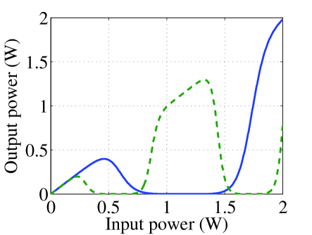
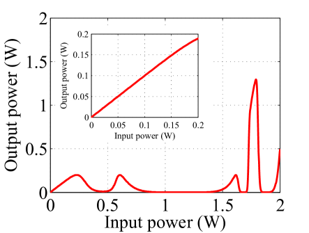
In order to extend the range over which the output power is limited, we consider a second waveguide with the same structural parameters as before, but of length m, with an output as shown in Fig. 4 (green); this plot is a compressed copy of the plot for , as follows from the scaling properties with respect to and . This second waveguide and polarizer are attached to the output end of the first waveguide, and the first polarizer then ensures that the initial conditions for the second waveguide are . The total output of the device as a function of is given by , which is shown in Fig. 4 (red). The output is linear for W, but is limited to values W for all input powers W. The maximum power operation range can be adjusted by varying the lengths and hence periods of the connected waveguides, and also by adding further stages. This conceptual design does not require any additional pumps for its operation, which is characteristic of the structurally-induced nonlinear polarization effects discussed previously [5, 6].
IV Conclusion
We have demonstrated the existence of nonlinear phase effects for waveguides with reduced symmetries, which are much larger than linear effects, at mW power levels. We have also demonstrated that switching behavior with polarization flipping can occur at the W input power level. Although we have analyzed properties of the system for the case of zero birefringence, this is convenient but not essential; the exact solutions described in [5, 6] allow one to determine the precise dependence of on the input power for any , including small nonzero values. The vectorial nonlinear model for subwavelength waveguides has enabled us to uncover these phenomena. Our results show that applications displaying this nonlinear polarization behavior can, in principle, operate at practical power levels.
References
- [1] S. Wabnitz, “Cross-Polarization Modulation Domain Wall Solitons for WDM Signals in Birefringent Optical Fibers,” IEEE Photon. Technol. Lett., vol. 21, no. 13, pp. 875–877, Jul. 2009.
- [2] V. V. Kozlov, J. Nuño, and S. Wabnitz, “Theory of lossless polarization attraction in telecommunication fibers,” J. Opt. Soc. Am. B, vol. 28, no. 1, pp. 100–108, Jan. 2011.
- [3] J. Fatome, et al., “Observation of light-by-light polarization control and stabilization in optical fibre for telecommunication applications,” Opt. Express, vol. 18, no. 15, pp. 15311–15317, Jul. 2010.
- [4] G. P. Agrawal, Nonlinear Fiber Optics, 4th ed., (Academic Press, New York, 2007).
- [5] W. Q. Zhang, M. A. Lohe, T. M. Monro, and S. Afshar V., “Nonlinear polarization bistability in optical nanowires,” Opt. Lett., vol. 36, no. 4, pp. 588–590, Feb. 2011.
- [6] S. Afshar V., M. A. Lohe, W. Q. Zhang, and T. M. Monro, “Polarization effects in a full vectorial model of pulse propagation in high index subwavelength waveguides,” arXiv:1203.6167
- [7] L. Vivien, et al., ”Polarization-independent single-mode rib waveguides on silicon-on-insulator for telecommunication wavelengths,” Optics Comm., vol. 210, pp. 43–49, Sep. 2002.
- [8] W. R. Headley, et al., ”Polarization-independent optical racetrack resonators using rib waveguides on silicon-on-insulator,” Appl. Phys. Lett., vol. 85, no. 23, pp. 5523–5525, Dec. 2004.
- [9] S. P. Chan, et al., “Single-Mode and Polarization-Independent Silicon-on-Insulator Waveguides With Small Cross Section,” J. Lightw. Technol., vol. 23, no. 6, pp. 2103–2111, Jun. 2005.