Analysis of the absorbing layers for the weakly-compressible lattice Boltzmann schemes
Abstract
It has been demonstrated that Lattice Boltzmann schemes (LBSs) are very efficient for Computational AeroAcoustics (CAA). In order to handle the issue of absorbing acoustic boundary conditions for LBS, three kinds of damping terms are proposed and added into the right hand sides of the governing equations of LBS. From the classical theory, these terms play an important role to absorb and minimize the acoustic wave reflections from computational boundaries. Meanwhile, the corresponding macroscopic equations with the damping terms are recovered for analyzing the macroscopic behaviors of the these damping terms and determining the critical absorbing strength. Further, in order to detect the dissipation and dispersion behaviors , the linearized LBS with the damping terms is derived and analyzed. The dispersive and dissipative properties are explored in the wave-number spaces via the Von Neumann analysis. The related damping strength critical values and the optimal absorbing term are addressed. Finally, some benchmark problems are implemented to assess the theoretical results.
keywords:
Computational aeroacoustics , Absorbing layers, LBS , Dispersion , Dissipation , Von Neumann analysis1 Introduction
In the past decades, there has been an increasing highlighted interest in developing and applying the LBS for aeroacoustic applications [1, 2, 3, 4, 5, 6], because the LBS has been developed into an innovative mescoscopic numerical method for the computational modeling of a wide variety of complex fluid flows and acoustics [1, 2, 3, 4, 5, 6, 7, 8, 9, 10]. In the field of the aeroacoustic applications, it has been demonstrated that the LBS possesses the low dispersion and low dissipation properties for capturing the weak acoustic pressure fluctuations [3, 4, 5, 6]. Recently, the MRT-LBM (multi-relaxation time lattice Boltzmann method [8, 11]) has been improved for the acoustic application with the nice dissipation and dispersion relations. The improvement of the MRT-LBM overcomes the drawback of the large bulk dissipation [1]. The improvement has made the MRT-LBM appearing as a very well-suited method for acoustic simulations.
In the simulations of the realistic flows, artificial computational boundaries are defined around the flow region of physical interest. The space outside the computational domain is neglected. In some cases, the region of interest should extend to infinity, especially for the computational aeroacoustics [12]. Because of the use of a finite computational domain and artificial boundary conditions (e.g. Dirichlet, Neumann or Robin types) the outcoming acoustic waves may be reflected. The reflected waves often have a significant influence on the flow field and may overwhelm the physical acoustic waves [12, 13, 14]. The obvious ways to suppress the reflected waves are to introduce artificial dissipation (by upwinding) or to increase the value of physical viscosity (or add hyperviscosity) [12]. The simplest way is to define sponge/absorbing layers is to add an additional penalty term to the governing equations to suppress the computed solution and to match a prescribed or precomputed solution [13, 14, 15]. The most used and efficient forcing term is given by [14]
| (1) |
where denotes the physical variables under consideration. Physically, the term (1) plays the role of a linear friction. Generally, the parameter , called the sponge strength, is a function that depends on space only and q_LABEL:$ denotes any variable of the far fields or time-dependent mean value). In most cases will vary smoothly between zero in the physical domain and a positive value in the absorbing laryer [13, 14, 15]. Provided is large enough, in the classical theory of absorbing layers, the outgoing disburbances are exponentially attenuated when crossing the layer[12, 14, 15, 16]. The numerical solutions inside absorbing layers need not be physical as long as the use of the region does not introduce significant reflection back into the physical domain. Meanwhile, the absorbing layer is numerically stable. Compared with perfectly matched layers, the absorbing layer techniques can be applied to a wider class of problems and are often coupled with the characteristic boundary condition [16].
The definition absorbing layers for LBS is an emerging resarch topic. It must be emphasized that there is a clear need for theoretical researches on that topic, to improce the potential of LBS for CAA applications. From the macroscopic equations standpoint, we are interested in the macroscopic variables which are obtained by the mesoscopic distribution statistics. We propose in the present paper several possible absorbing terms which are enforced on LBS. By the classical Chapman-Enskog multi-scale expansion, the macroscopic systems are recovered in the absorbing layer. With the aid of the macroscopic systems, the related analysis is implemented in spectral space. The emphasis is put on the coupling between and LBS relaxation parameters, especially on finding the critical value for . The critical expressions of will offer us a guide for choosing the reasonable absorbing strength. This is different from the classical absorbing layer theory in Navier-Stokes equations (NSEs). In the classical absorbing layer theory, can be regarded as a penalized parameters, and theoretically, can be chosen as any positive real number. However, in order to avoid a stiff problem, will not be chosen very large. In LBS, is a finite parameter dependent on the relaxation parameters, as shown hereafter.
In next section, the fundamentals of LBS are reviewed and the possible absorbing terms are proposed. In the third section, in the spectral space, the dispersion and dissipation relations are analyzed with the aid of Von Neumann method considering monochromatic wave solutions. In the fourth section, the numerical simulations are performed to validate the proposed absorbing terms considering some benchmark problems.
2 Fundamentals of LBS and absorbing terms
In this section, the fundamental theory of LBS is briefly reviewed. Then, we give the linearized LBM problem coupled with absorbing terms and establish the relation between the classical BGK-LBM and the Navier-Stokes equations in absorbing layers.
2.1 Lattice Boltzmann schemes
The governing equations of the lattice Boltzmann schemes are described by the following universal form [8, 11]
| (2) |
where belongs to the discrete velocity set , is the discrete single particle distribution function corresponding to and denotes the discrete single particle equilibrium distribution function. Generally, can be expressed by a combination of a linear part and a quadratic part [9]
| (3) |
denotes the time step and is the number of discrete velocities. is the generalized relation matrix. From here on, the repeated index indicates that the Einstein summation is used except for some special explanations. Let ( denotes the spatial dimension) denotes the lattice system, and the following condition is required [2]
| (4) |
that is to say, if is a node of the lattice, is necessarily another node of the lattice. Generally, for BGK-LBM, the relaxation matrix is given by
| (5) |
where denotes the relaxation frequency of BGK-LBM. If the relaxation matrix is defined by
| (6) |
where is a diagonal matrix which denotes the relaxation parameters of MRT-LBM, which is given by
| (7) |
is the transformation matrix (see A for details of D2Q9 and D3Q15), which satisfies the following basic conditions [8]
| (9) |
By the simple algebra, the standard isothermal MRT-LBM is recovered in the following form [2, 8]
| (10) |
and
| (11) |
It is necessary to point out that for isothermal flows, the number of the conservative quantities is equal to . According to the work of Lallemand and Luo [8], the relaxation parameters in Eq. (11) should satisfy the following stability constraints
| (12) |
2.2 Absorbing terms
Following the theory of Israeli & Orszag [14], Eq. (2) coupled with the absorbing terms has the following form
| (13) |
where is the generalized absorbing strength defined by
| (14) |
and denotes the reference state of and denotes the possible representations of mesoscopic distribution functions. From the classical theory, a natural choice of is . The matrix in the expression (14) is defined by
| (15) |
where is the absorbing coefficient for each first-order moment of . In the expression (14), the transformation matrix is given in A. The choice of the generalized absorbing strength expression (14) is based on the ideal for the different modes, the different absorbing strength can be applied as indicated in [13]. For simplicity, we consider , and the matrix become the following diagonal form
| (16) |
In this paper, the researches are focused on the absorbing strength with the form (16) .
Generally, the reference distribution function is expressed by the time-averaged mean value [16]. Here, we define the expression of by the equilibrium distribution function as follows
| (17) |
where and denote the reference (or base) density and velocity, respectively. Especially, let and denote the far fields. The influence of the absorbing terms on the macroscopic equations can be interpreted as the source terms of the macroscopic equations. Based on this consideration, the corresponding source terms can be obtained by the classical Chapman-Enskog procedure.
It is necessary to discuss the choices of and . Intuitively, let and expressed by the equilibrium distribution functions. This consideration makes us easy to analysis the macroscopic behaviors of the absorbing layers. Meanwhile, from these choices, we only need to handle the macroscopic statistical quantities and reference quantities. Compared with handling the distribution functions, these choices are effective and simple. Especially, provided you consider the time-dependent mean quantities as the reference state, the time-dependent mean of the macroscopic statistical quantities is easier to be handled than the mesoscopic distribution functions from the view of saving memory and CPU cost. Another more careful consideration is that generally, for aeroacoustic problems, if the background flows or far fields are used, it is difficult to construct a suitable . If is defined by the equilibrium distribution functions, this will lead to some potential instabilities when is defined by . The analysis will be given in Sec. 3. From above considerations, there exist three-kind simplest absorbing terms.
2.2.1 Type I absorbing term
Combining Eq. (13) and Eq. (17) and using the far field as the reference state, and considering and we have
| (18) |
where , is defined by
| (19) |
In Eq. (18), and denote the density and velocity, which are defined by the following parameterized forms [17]
| (20) |
Then, we have the following macroscopic equations (see B for details)
| (21) |
where , , , and are defined by
| (22) |
According to the definition of the effective relaxation frequency , it is known that for Eq. (18), an effective negative viscosity will appear, if satisfies the following condition
| (23) |
2.2.2 Type II absorbing term
According to the deviation in Sec. 2.2.1 and considering and , we propse the second-type absorbing term for LBS
| (24) |
where is defined by
| (25) |
In Eq. (24), and denote the density and velocity, which are defined by the following parameterized forms [17]
| (27) |
where , and are defined by
| (28) |
The difference between Eq. (18) and Eq. (24) lies in the relaxation frequencies and . In Eq. (24), the effective relaxation frequency is kept in the original form while, in Eq. (18), the original relaxation was modified, possibily leading to a negative viscosity if is too large. This problem is now cured.
2.2.3 Type III absorbing term
In the recovered macroscopic equations (21) and (27), in the left hand side, there exist momentum-velocity coupled terms in recovered equations. Considering and , these terms can be dropped by the following third type absorbing term
| (29) |
where is the equilibrium velocity. is defined by
| (30) |
In Eq. (29), and denote the density and velocity, which are defined by the following parameterized forms [17]
| (31) |
Then, the following macroscopic equations are obtained (see B for details)
| (32) |
where the parameters , and are defined as follows
| (33) |
In this section, the fundamental theories of LBS are reviewed. Based on the classical absorbing layer strategies, the three types of absorbing terms are proposed for LBS, and the corresponding macroscopic equations are given. In the following section, the behaviors of the absorbing terms are studied.
2.3 Profiles of absorbing strength
In the absorbing layers, the profile of could not be specified as a uniformly distributed parameter. A uniform distribution will induce a significant wave reflection from the interfaces between the wave propagation domain and the sponge domain [13, 14]. The most popular profiles of are listed in Table 1. In the current research, the first kind of will be used which was first proposed in [14]. For this kind of absorbing profile, satisfies . In the original paper of Israeli and Orszag [14], by taking , they obtained the best results for the acoustic wave equation. In order to handle the current problem, we given following normalized for as follows
| (34) |
The normalized profile for and is given in Fig. 1

| Damping Types | Parameters | |
|---|---|---|
| Polynomial | : Position of sponge layer; : Absorbing strength; : Width of sponge layer; for most choices, . | |
| : Absorbing strength; : Width of sponge layer; . | ||
| Reyleigh | : Position of sponge layer; : Absorbing strength. |
3 Analysis of LBS coupled with absorbing terms
In this section, the influences of the absorbing terms on the dissipation/dispersion properties are explored looking at the linearized forms of the recovered macroscopic equations and LBS.
3.1 The linearized macroscopic equation with the absorbing terms
| (35) |
where denotes or , denotes or , and Eq. (32) can be rewritten as follows
| (36) |
In order to detect the dissipative behavior, we consider the following simplified 1D case of Eq. (35) (the flow propagation is only along x-axis)
| (37) |
We consider the following decomposition of and
| (38) |
For the sake of simplicity, we take and , leading to the following linearized system
| (39) |
From the above equations, we obtain
| (40) |
where , and .
Now, considering a monochromatic wave solution , we get the following relation
| (41) |
Considering a monochromatic solution, the similar relation for the linearized form of Eq. (39) can be obtained as follows
| (42) |
If vanishes in Eq. (39), then, we are left with the following 1D form
| (43) |
The above equation is different from the classical 1D model
| (44) |
Mathematically, the above classical absorbing strategy is similar to the penalty method [13]. As indicated, if is suitably smooth and the norm suitably large, the spatial derivatives of will be negligible compared with the right hand side. Eq.(44) and the solution decays exponentially with the time scale [13]. If , the right hand side terms will not dominate Eq. (44) and the convergence property will depend on the initial condition and the coercivity of the convection operator. From the viewpoint of penalty methods, and could be chosen as any positive large numbers. Now, let us rewrite Eq. (43) as follows
| (45) |
We now consider and , . It is clear that is negative. That means if the following inequality is satisfied
| (46) |
the effective coefficient defined by
| (47) |
will become negative and LBS will be unstable. This phenomenon is different from that in Eq. (44). Further, by and , we have
| (48) |
If , the correct effective sound speed will be recovered. As indicated in Sec.1, LBS solution in absorbing layers is not required to be physical, so it is not necessary for to be equal to 2. Clearly, because of the collision term in LBS, the classical absorbing layer theory can not be used completely and directly.
As indicated in Sec. 2.2.1, for the type I absorbing term, because of the definition of the effective relaxation , if the condition (23) is satisfied, the instability will grow very fast. In practical applications dealing with acoustic problems, because of the nearly vanishing viscosity, is close to 2 and it is impossible to choose suitable and positive . Therefore, the type I absorbing term is not well suited for absorbing acoustic waves.
In the same way, we can get the following equation for the type III absorbing term
| (49) |
If , in order to keep the sound speed uniform and different from 0, the choice of must satisfy the following equality
| (50) |
However, this requirement is not necessary for the sound speed. The critical value of for stability is given by
| (51) |
The positivity constraint on requires the following inequality should be satisfied
| (52) |
From the above inequality, it is easy to see that if is close to 2, the choice of will become very optional. If we set , the constraint on is natural ().
The numerical investigations will be presented in Sec 3.3, which are mainly focused on the type II and type III absorbing terms.
3.2 The linearized LBS with the absorbing terms
In order to give the linearized LBM with the absorbing terms, we consider the following general form
| (53) |
where the absorbing term is given by
| (54) |
Regarding and as the uniform reference states, the reference is defined by
| (55) |
The fluctuating quantity is defined by
| (56) |
Using the definitions of and , and considering , the linearized version of Eq. (53) is depicted by
| (57) |
where is calculated by
| (58) |
Then, considering a plane wave solution of the linearized equation
| (59) |
we get the following eigenvalue problem for the L-MRT-LBM in the frequency-wave number space [4, 5, 8]
| (60) |
The matrix in Eq. (60) is defined by
| (61) |
For the sake of comparison with the linearized isentropic Navier-Stokes equations, it is recalled that the analytical acoustic modes and shear modes are given by [20]
| (62) |
where is the shear viscosity and is the bulk viscosity.
3.3 Von Neumann Analysis for D2Q9 model in spectral spaces
In the above section, the linearized LBS with the absorbing terms was given. In this section, combining the analysis presented in Sec. 3.1 and the linearized form (60) in spectral spaces, the numerical dissipative and dispersive properties will be analyzed thanks to Von Neumann theory. The parameter for the standard LBS is equal to 1. For the sake of convenience, and without loss of gnerality, let us choose and in Eqs. (35) and (36). For , the molecular viscosity vanishes. One also consider . In order to keep the numerical investigation identical to the theory given in Sec. 3.1, let and . The wavenumber in Eq. (59) is defined by
| (63) |
Now, let us discuss the stability of the type I absorbing term. In Fig. 2, the dissipation relations for the type I absorbing term are shown for two different values of the parameter . As indicated by the inequality (23), in Fig. 2(a), the effective relaxation parameter is equal to 2 and the LBS is stable. When the effective relaxation parameter is larger than 2, it can be observed in Fig. 2(b) that there exist some modes which become unstable. Therefore, type I absorbing term is useless for LBS.


(a) & (b) &
We now investigate the second and third type absorbing terms. First, let us assess the critical value of the absorbing strength in Eq. (46). If , the effective absorbing strength in Eq. (47) will become singular and the corresponding dissipation relations are illustrated in Fig. 3. It is easy to observe that under this condition, for two values of ( or ), the corresponding LBS is stable. Further, if is larger than , we can observe from Fig. 4 that most modes are unstable. These observations validate the theoretical analysis presented in Sec. 3.1. The dispersion relations for smaller are displayed in Fig. 5. From these results, it is seen that all modes are stable. From Fig. 6, the dispersion errors disappear. Certainly, if becomes small, the dispersion error will appears again. The suggestion for the choice of is that for nearly vanishing viscosity acoustic problems, the magnitude of is in the range [0,2]. Theoretically, there exist similar results for the type II and type II absorbing terms. Further, let us investigate the type II absorbing term by the von Neumann method for several cases . In Fig. 7 , dissipation is shown for two choices of . It is easy to conclude that when is larger than the critical , LBS is unstable; otherwise, LBS is stable.
We consider and . In Fig. 9, is parallel to and the dissipation is given for the type II absorbing term. Looking at these results, it is clear that the critical of is suitable for that of . The same phenomenon can be observed. However, this kind of phenomenon can not be observed for the type III absorbing term. Corresponding results are displayed in Fig. 10. is not a critical value for the type III absorbing term. Numerical validation shows that the critical value of is smaller than . So, it can be concluded that the type II absorbing term is the best suited absorbing term for LBS. Meanwhile, we can obtain that for LBS, when the far field is not equal to 0, the absorbing terms should damp all possible physical quantities in the macroscopic systems. This is different from the classical absorbing layer for compressible Navier-Stokes equations.


(a) & (b) &


(a) & (b) &


(a) & (b) &


(a) & (b) &

(a) & (b) &


(a) & (b) &


(a) & (b) &


(a) & (b) &
4 Numerical assessment
In this section, the type II absorbing term is assessed by solving numerically some classical acoustic problems. All numerical investigations were implemented in PalaBos [23].
4.1 2D acoustic pulse
We first consider a 2D acoustic pulse source. Assuming that the viscosity effect is negligible on acoustic waves, the acoustic pulse problem possesses an analytical solution [1, 22]. The initial profile is given as follows
| (64) |
where , , , and are defined by
| (65) |
The computational domain is a square. And the characteristic length is equal to 1. The parameter in Eq. (65) is equal to 1/20. The exact solution of (if ) is given by [22]
| (66) |
where and is the Bessel zeroth-order function of the first kind. The adopted lattice resolution is . For the sake of convenience, we define the following rescaled time unit
| (67) |
Theoretically, when a sponge layer is enforced around the computational domain, after several time units, the wave propagate outside the domain and the fluid flow field should converge to the steady reference flow. The time for this phenomena is equal to . The ideal state is that the density fluctuation in the computational domain vanishes. In order to address this phenomena, one defines the relative error as
| (68) |
For the current investigations, in the initial condition (64).

The computational domain with the absorbing layer is shown schematically in Fig.11. The normalized denoted by the formula (34) will be used. The absorbing strength is chosen equal to , where denote a small positive constant. The new for this problem is defined by
| (69) |
In order to validate influence of the absorbing layer thickness, the thickness of the absorbing layer is chosen equal to (where is a positive integer). The current investigations will be compared with the viscosity absorbing strategy, which consists in linearly decreasing the relaxation frequency from the physical value to 1 in the sponge region. The Reynolds number of this problem is defined by and the viscosity nearly vanishes. For all simulations, the Dirichlet boundary condition is used.
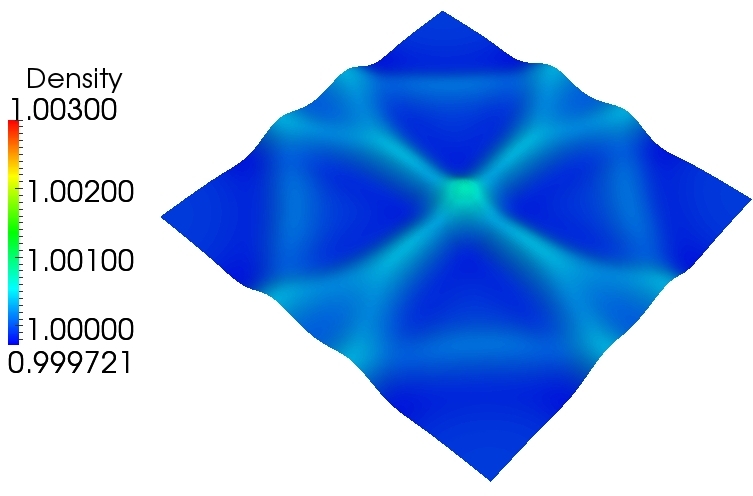
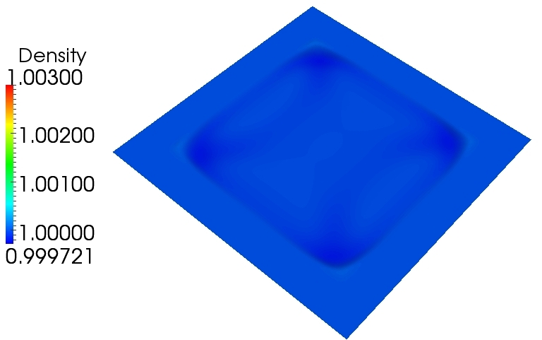
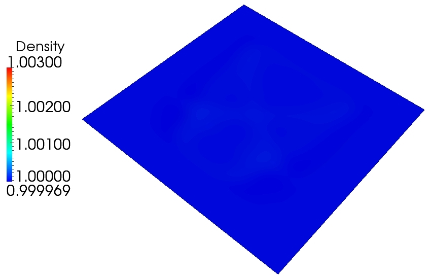
The initial density profile is displayed in Fig.12. In Fig.13, the density profiles obtained using the three different strategies are shown at different times for a zero mean flow. One can see that without any absorbing strategies a clear wave reflection from the boundaries is present. With the linearly decreasing relaxation parameter, there still exits a significant wave reflection. With type II absorbing term, only a very weak wave reflection is observed. Especially, when the wave propagates across the absorbing layer, it is hardly possible to observe the wave trace. In Fig.14, a quantitative comparison based on is shown. Some clear differences can be observed and type II term is the best one. Meanwhile, it can be concluded that using the viscosity damping strategy, the absorbing performance is weak. From the given reference line, it can be concluded that the wave in the proposed absorbing layer exhibits a fast decay with a decay exponent about .
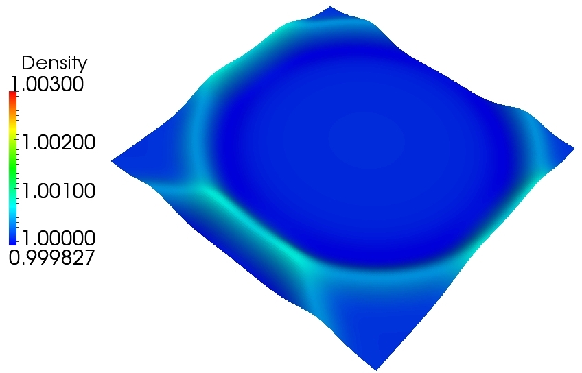
In order to validate the type II absorbing term in the presence of a uniform base flow, the computational results are given in Figs. 15 and 16. It is observed in the absorbing layer, the wave has a fast decay exponent about -3. In Fig.17, the error is given. From this figure, it is easy to see that when the thickness of the absorbing layers increases, the error decreases. Meanwhile, a fast decay exponent close to -3.5 is measured.
These investigations demonstrate that the optimal absorbing term (24) is very efficient in suppressing the wave reflection from the computational domain boundaries.
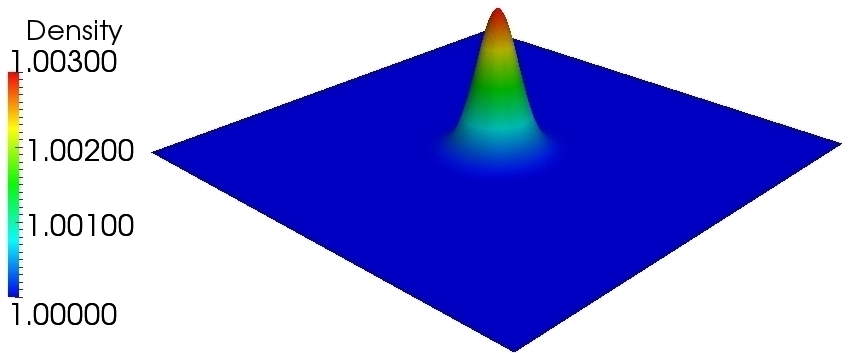
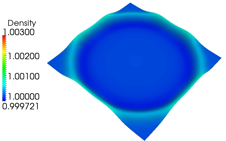
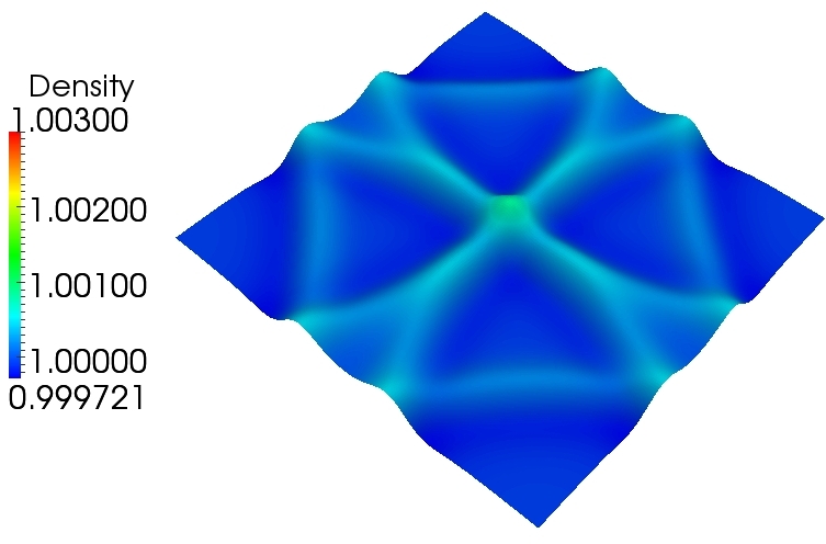
(a-1) At the time unit (a-2) At the time unit
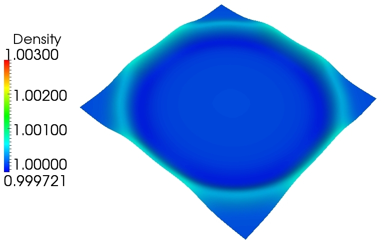
(b-1) At the time unit (b-2) At the time unit
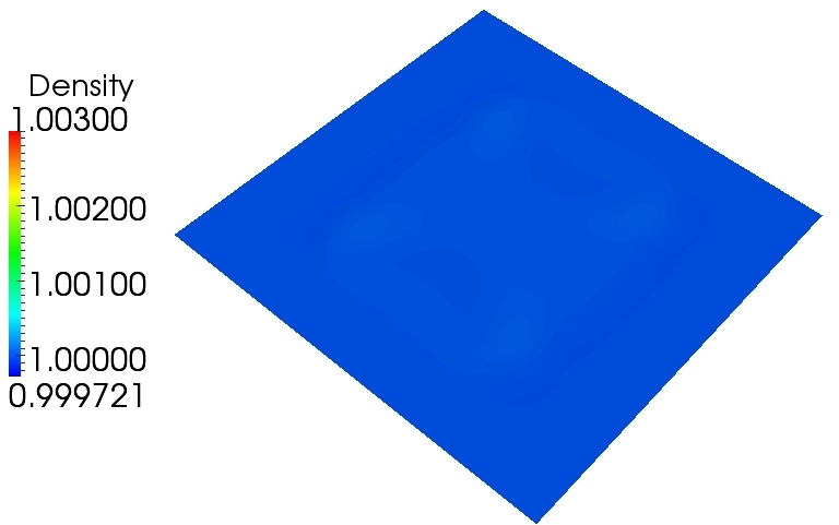
(c-1) At the time unit (c-2) At the time unit

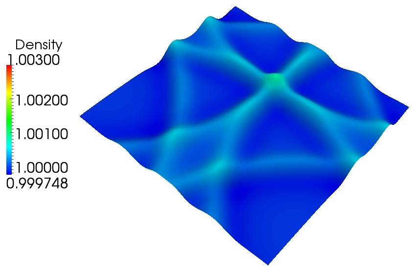
(a-1) At the time unit (a-2) At the time unit
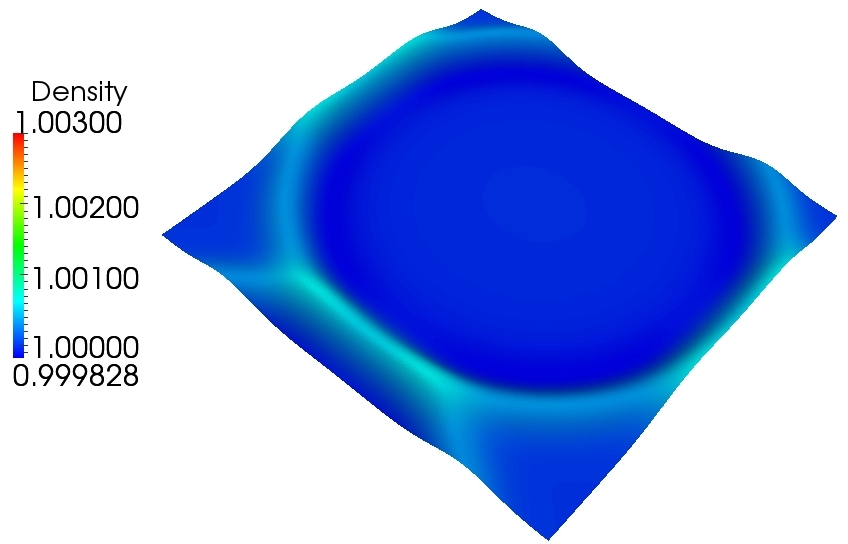
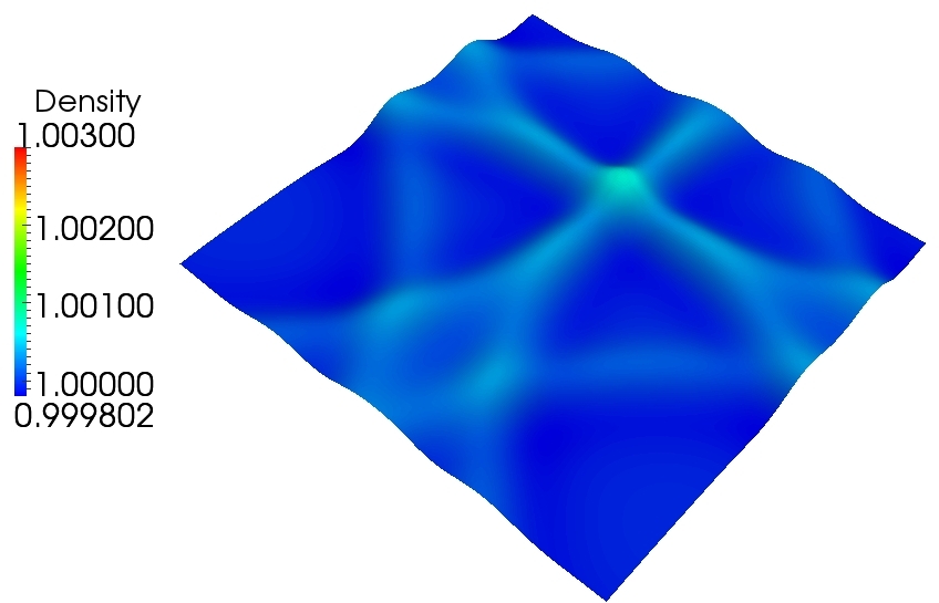
(b-1) At the time unit (b-2) At the time unit
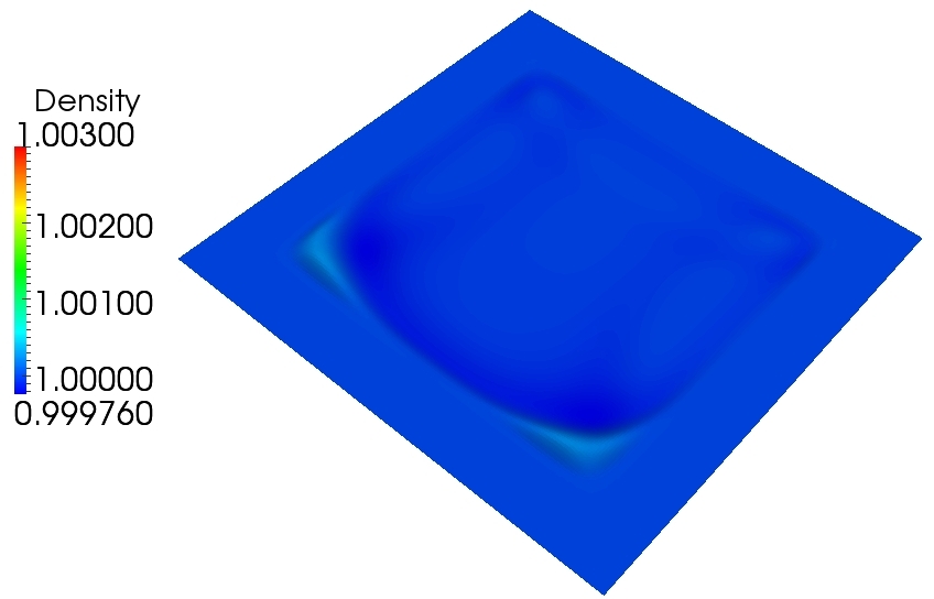
(c-1) At the time unit (c-2) At the time unit


4.2 Validations for time dependent acoustic line source
In order to validate the absorbing term II for a time-dependent acoustic source, the case of an acoustic line source with and without background flow is chosen. The profile of the acoustic line source is described by
| (70) |
where the frequency . The corresponding wave length is . The schematic domain with the absorbing layer is shown in Fig. 18. For present computations, the domain width is and the domain height is , respectively, and the width of the absorbing layer is 0.8. The acoustic line source is fixed at the left boundary . Periodic boundary conditions are enforced at the top and bottom boundaries. The outflow boundary condition is adopted for the right boundary . For the sake of convenience, we introduce two characteristic time scales for zero mean flows:
| (71) |
where , and are the time step, the time of the wave propagation to the right boundary and the time of the wave propagation for one wave length, respectively. With the mean flow along -axis, is defined by
| (72) |
where is the mean flow velocity along -axis. The number of grid points used for this configuration is . The absorbing strength is chosen equal to , where . .
In Figs.19 and 20, the computational results for both zero and non-zero background flow are shown. It is observed that using the optimal absorbing strategy (24), the wave in the absorbing layer are almost completely damped after a short travel distance. Although the given thickness of the absorbing layer is equal to 0.8, the required minimal thickness is smaller than 0.3, i.e. about one wavelength . Therefore, for this kind of problems, the thickness of the absorbing layer can be set to equal to the characteristic wave length or a little larger than the characteristic wave length of the acoustic wave.


4.3 Validations of a dipole advected by the mean flow
The validation of the optimal absorbing strategy (24) for the vortical flows is very important for the turbulent aeroacoustic problems [16], because of the significance of the practical applications. Here, we consider the case of a dipole vortex advected by a uniform flow. The dipole is given by
| (73) |
The vorticity distribution of the isolated monopoles has the following Gaussian form
| (74) |
If we set , the initial total kinetic energy of the dipolar flow field
Considering the mean flow, for the LBS, the initial field is set as
| (75) |
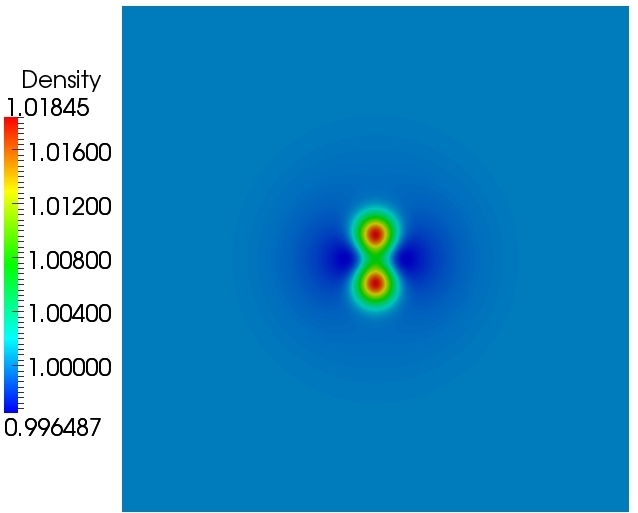
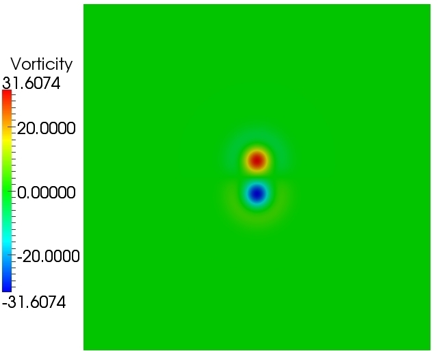
where . The computational domain is defined as . The parameters in Eq.(75) :are taken equal to , , , and . The Reynolds number is set equal to and the computational grid is equal to . The computational domain with the absorbing layer is similar with the computational domain indicated by Fig.11. The thickness of the absorbing layer is taken equal to . The initial pressure is obtained by solving the pressure Poisson equation and the initial distribution is initialized by the method given in [9]. The far field boundary condition is used. The following normalized averaged enstrophy will be investigated
| (76) |
By monitoring , the absorbing behavior of the proposed optimal absorbing strategy will be validated for vortex flows. In all figures, if considering the physical reference velocity is equal to 1, the following time scale is used for the LBS computations
| (77) |
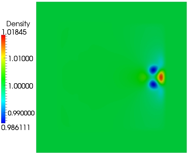
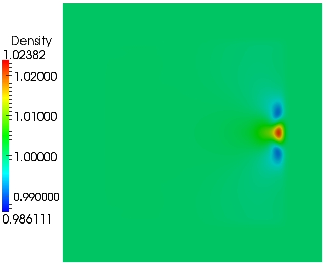
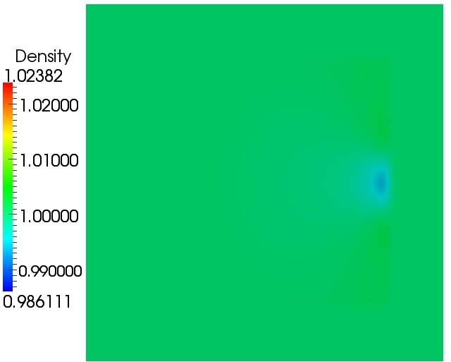
The initial density field and vorticity field are given in Fig.21. In Fig.22, the evolution of the density and vorticity fields is shown with at three different rescaled times. At the first time shown, the dipole is reaching the absorbing layer. At the second time, it is crossing the absorbing layer, while the third snapshot corresponds to a time at which the dipole should have left the full computational domain. It is seen that the outlet boundary condition does not radiate any spurious wave. The efficiency of type II absorbing layer is measured monitoring time evolution of the enstrophy (see Fig.23). A very fast decay is observed, with a decay exponent close to -12.
(a)Initial density fields (b) Initial vorticity field
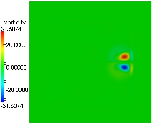
(a-1) Density fields at (b-1) Vorticity field at
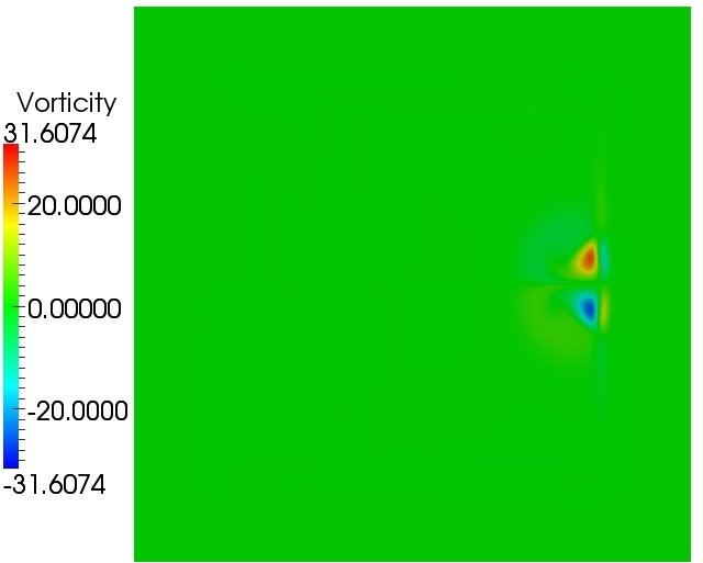
(a-2) Density fields at (b-2) Vorticity field at
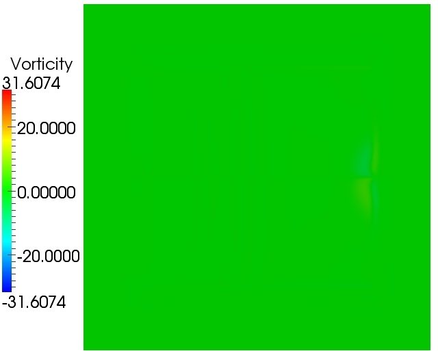
(a-3) Density fields at (b-3) Vorticity field at

4.4 Flow past two cylinders
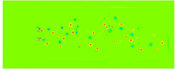
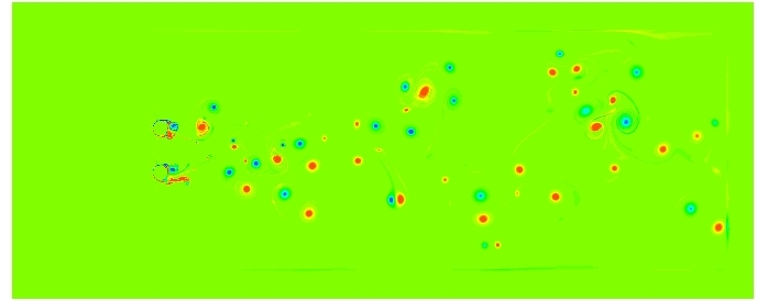
In order to further illustrate the capability of the optimal absorbing layer, the flow past two cylinders with equal diameters is considered. The computational domain is drawn schematically in Fig. 24. The centers of the two cylinders are located at and where is the diameter of the cylinders. The thickness of the absorbing layer is taken equal to . The Reynolds number is ( denotes the field field mean velocity magnitude). The Mach number is . The mesh resolution is equal to . For convenience, the following dimensionless time scale is introduced
| (78) |
The reference field velocity and the reference density . The three snapshots of the flow fields (density, dimensionless velocity magnitude and dimensionless vorticity) are given in Figs.2527 for , and , respectively. The very satisfactory quality of the results show that the proposed type II absorbing layer can be used to handl complex vortical flows.

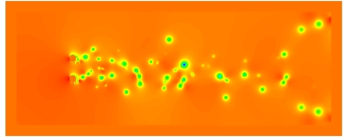
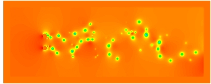
(a) (b)
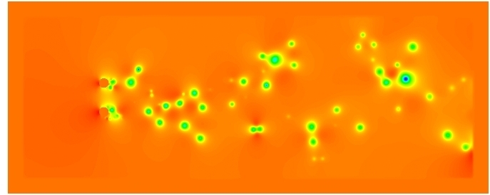
(c)
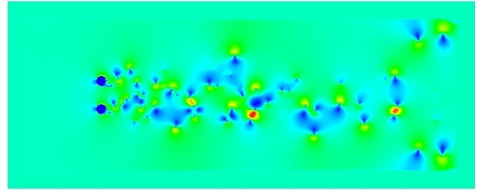
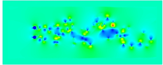
(a) (b)
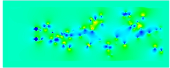
(c)
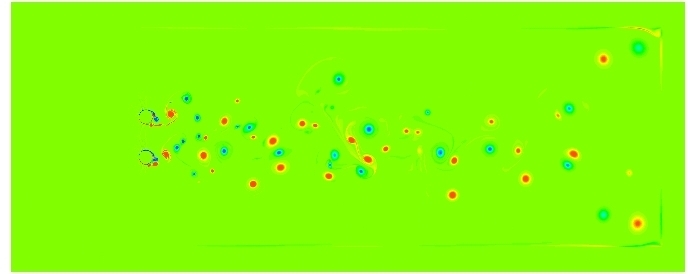
(a) (b)
(c)
5 Conclusion
A new absorbing layer technique for the definition of non-reflecting boundary conditions for Lattice-Boltzmann methods has been proposed. Thank to an original theoretical analysis of the associated linearized problem, dispersive and dissipative features of the method have been analyzed. An interesting result is that the associated sponge layer equation for the associated macroscopic problem is more complicated that sponge layer equations directly defined on macroscopic quantities. By recovering the corresponding macroscopic equations, the macroscopic effect of the absorbing terms is identified and the critical absorbing strength value is formulated. Performing mathematical analysis in the spectral space, the influence of critical parameters are investigated. From this analysis, an optimal absorbing strategy is obtained. By simulating two basic acoustic problems, the optimal absorbing strategy is validated and the corresponding decay exponent is obtained. Numerical results show that the optimal absorbing strategy is also powerful for damping vortices. A very high damping exponent for the enstrophy is observed. The results demonstrate that the optimal absorbing strategy Type II is very effective for coping with vortical flows.
Acknowledgement
This work was supported by the FUI project LaBS (Lattice Boltzmann Solver, http://www.labs-project.org).
Appendix A Transformation matrices
A.1 For two dimensional MRT-LBM with 9 discrete velocities
The transformation matrice for MRT-LBM with 9 discrete velocities is described by
| (79) |
A.2 For three dimensional MRT-LBM with 15 discrete velocities
The transformation matrice for MRT-LBM with 15 discrete velocities is described by
| (80) |
Appendix B The macroscopic equations with the absorbing layer for the BGK model
B.1 The classical absorbing layer
The BGK model with the absorbing layer is given by ()
| (81) |
where and are the equilibrium density and velocity, respectively. Eq. (81) can be rewritten as follows
| (82) |
where and is defined by
| (83) |
Eq. (82) can be regarded as the new LBS with a special external force term. In order to obtain the macroscopic equation corresponding to Eq. (82), the classical Chapman-Enskog derivation [17, 21] is used. The following expansions are introduced [21]
| (84) |
| (85) |
By the multi-scale expansion, we have
| (86) | |||
| (87) | |||
| (88) |
where . Eq. (100) can be expressed as follows
| (89) |
Here, we define the macroscopic quantities (, ) as follows
| (90) |
It is easy to get the following relation
| (91) |
So, has the following properties
| (92) |
and
| (93) |
At the scale , we have
| (94) |
| (95) |
where the second-order tensor is defined by
| (96) |
At the scale , we have
| (97) |
| (98) |
Now, let us calculate . From Eq. (87), we have
| (99) |
Then, we have
| (100) |
where and .
Eq. (100) can be rewritten as follows
| (101) |
Combining Eqs. (94), (95), (97) and (B.1), ignoring the term of we obtain
| (102) |
| (103) |
From the defination of , we have
| (104) |
So, by Eq. (B.1), we have
| (105) |
| (106) |
Let and defined by
| (107) |
| (108) | |||
| (109) |
B.2 The absorbing layer based on the equilibrium distribution functions for the BGK model
B.3 The absorbing layer based on linear damping terms
In B.1, the absorbing terms are specified based on the equilibrium distribution functions. From Eq. (B.1), it is known the obtained damping terms in the recovered Navier-Stokes equations involves a nonlinear damping term (the second order terms of the velocity and ) in momentum equations. The following model is propsed for elinimating this term
| (113) |
where is the equilibrium velocity. is defined by
| (114) |
Then, along the routine in B.1, the following macroscopic equations are obtained
| (115) |
where the parameters , and are defined as follows
| (116) |
References
- [1] H. Xu, P. Sagaut, Optimal low-dispersion low-dissipation LBM schemes for computational aeroacoustics, J. Comput. Phys 230 (13): 5353-5382 (2011)
- [2] F. Dubois, P. Lallemand, Towards higher order lattice Boltzmann schemes, J. Stat. Mech. Theory E, (2009) P0600.6
- [3] J. M. Buick, C. A. Greated, D. M. Cmpbell, Lattice BGK simulation of sound waves, Eurohys. Lett. 43 (2) (1998) 235-240.
- [4] S. Marié, D. Ricot, P. Sagaut, Comparison between lattice Boltzmann method and Navier-Stokes high order schemes for computational aeroacoustics, J. Comput. Phys. 228 (2009) 1056-1070.
- [5] D. Ricot, S. Marié, P. Sagaut, C. Bailly, Lattice Boltzmann method with selective viscosity filter, J. Comput. Phys. 228 (2009) 4478-4490.
- [6] J. M. Buick, C.Spectra and L. Buckley, C. A. Greated, Lattice Boltzmann BGK-simulation of non-linear sound waves: The development of a shock front, J. Phys. A: Math. Gen. 33 (2000) 3917-3928.
- [7] S. Chen, G. Doolen, Lattice Boltzmann method for fluid flows, Annu. Rev. Fluid Mech. 161 (1998) 329.
- [8] P. Lallemand, L. S. Luo, Theory of the lattice Boltzmann method: Dispersion, dissipation, isotropy, Galilean invariance, and stability, Phys. Rev. E. 61(6) (2000) 6546-6562.
- [9] H. Xu, H. B. Luan, Y. L. He, W. Q. Tao, A lifting relation from macroscopic variables to mesoscopic variables in lattice Boltzmann method: Derivation, numerical assessments and coupling computations validation, Computers & Fluids, doi:10.1016/j.compfluid.2011.10.007, 2011.
- [10] H. Xu, W. Q. Tao, Y. Zhang, Lattice Boltzmann model for three-dimensional decaying homogeneous isotropic turbulence, Physics Letters A, 373 (15) (2009) 1368-1373.
- [11] D. d’Humières, I. Ginzburg, M. Krafczyexact solution of k, P. Lallemand, L. S. Luo, Multiple-relaxation-time lattice Boltzmann models in three dimensions, Phil. Trans. R. Soc. Lond. A, 360 (2002) 437-451
- [12] T. Colonius, Modeling artificial boundary conditions for compressible flow, Annu. Rev. Fluid Mech. 36 (2004): 315-345.
- [13] D. J. Bodony, Analysis of sponge zones for computational fluid mechanics, J. Comput. Phys. 212 (2006) 681-702.
- [14] M. Israeli, S. A. Orszag, Approximation of radiation boundary conditions, J. Comput. Phys. 41 (1981) 115-135.
- [15] J. B. Freund, A simple method for computing far-field sound in aeroacoustic computations, J. Comput. Phys. 157 (2000) 796-800.
- [16] C. A. Wagner, T. Hüttl, P. Sagaut, Large eddy simulation for acoustics, New York: Cambridge University Press, 2007.
- [17] Z.L. Guo, C.G. Zheng, B.C. Shi, Discrete lattice effects on the forcing term in the lattice Boltzmann method, Phys. Rev. E. 65 (2002): 046308.
- [18] D.R. Durran, Numerical methods for fluids dynamics with applications to Geophysics, Springer New York Dordrecht Heidelberg London, 2010.
- [19] R.R. Renaut, J. Fröhlich, A pseudospectral Chebychev method for the 2D wave equation with domain stretching and absorbing boundary conditions, J. Comput. Phys. 124 (1996) 324-336.
- [20] L.D Landau, E.M. Lifshitz, Fluid Mechanics,second ed., Oxford: Pergamon, 1987.
- [21] J.M. Buick, C.A. Greated, Gravity in a lattice Boltzmann model, Phys. Rev. E, 61 (5) (2000): 5307-5320
- [22] C.K.W. Tam , J.C. Webb, Dispersion-relation-preserving finite difference schemes for computational acoustics, J. Comput. Phys. 107 (1993) 262-281
- [23] User’s Guide, http://www.lbmethod.org/palabos/.