Realizing a variable isotropic depolarizer
Abstract
We demonstrate an isotropic depolarizing channel with a controllable degree of depolarization. The depolarizer is composed of four birefringent crystals and half-wave plates. Quantum process tomography results of the depolarization effect on single photons agree well with the theoretical prediction. This depolarizer can be used to test quantum communication protocols with photons.
pacs:
03.65.Yz, 42.25.Ja, 03.67.Pp, 42.50.Lc, 42.79.-eThe study of light depolarization is fundamental to the field of optics. Optical devices that completely depolarize light are desirable when polarization dependent effects need to be eliminated Bohm81 ; Wang99 . The Lyot depolarizer, which was invented more than eighty years ago, is an example for such a device.Lyot In the last 15 years, many experiments have encoded quantum information in the polarization of single photons Mattle96 ; Gisin02 . The polarization of each photon represents a two-state quantum system, a qubit. The depolarization process is interpreted as channel induced noise which results in decoherence of the photonic qubit. In order to study the effect of noise on quantum information channels, there is a need for a physical realization of controlled depolarization processes. Previously, photonic noisy channels which partially depolarize light were implemented in several ways Kwiat_Dephasing ; Puentes_Wedge ; Almeida_ESD ; Karpinski ; Shaham ; Chiuri . Here, we report on the implementation of a simple controllable isotropic depolarizer, which depolarizes to the same extent light of any initial polarization, to any required final degree of polarization.
The Lyot depolarizer is composed of two birefringent crystals, where one crystal is twice as long as the other and their principal axes are oriented at with respect to each other. The Lyot depolarizer completely depolarizes light whose coherence length is shorter than the polarization temporal walk-off in the shorter crystal:
| (1) |
where is the length of the shorter crystal, is its birefringent refractive index difference and is the speed of light. The birefringent crystals couple between the polarization and the temporal degrees of freedom: every crystal entangles the polarization degrees of freedom with two different temporal modes. Depolarization occurs because photon detection can not resolve between the different temporal modes. The addition of more crystals will further increase the number of temporal modes. Adding wave-plates before the crystals and between them (or rotating the crystals) affects every temporal mode separately, and adds more possibilities to the depolarization process. The combined depolarization process of the crystals and the wave-plates can be explicitly calculated for any configuration Shaham .
The polarization state of a single photon, as well as of classical light, can be described either by its density matrix , or by a point in the Poincaré sphere representation. The Cartesian coordinates of this point are the Stokes parameters , where . Here we use the convention that represents the linear horizontal and vertical polarizations and , the linear diagonal polarizations , and , and the circular polarizations and ). The length of the Stokes vector is the state’s degree of polarization. For polarized states , whereas for partially polarized states . The center of the Poincaré sphere represents the completely unpolarized state. Characterization of the polarization state is performed by several projection measurements using the Quantum State Tomography (QST) procedure Kwiat_Tomo .
Given a depolarizing configuration, its effect on any input polarization state can be described by the mapping . The map can be uniquely described by the elements of the positive Hermitian process matrix :
| (2) |
where are matrices that span the vector space of . Assuming the channel has no dissipation (e.g. light intensity is preserved), the matrix satisfies . The elements of the matrix can be experimentally determined by a Quantum Process Tomography (QPT) procedure which requires several QST measurements Chuang . When no depolarization occurs, has one eigenvalue that equals 1, and the rest are zeros. If two or more eigenvalues of differ from zero, the channel depolarizes light. Isotropic depolarization occurs when the degree of polarization of the output state is equal for any initial polarized state. Such a process is described by a matrix with three nonzero equal eigenvalues. A complete depolarization occurs when all four eigenvalues of are equal. In the Poincaré sphere representation, a general depolarizing channel is described by mapping the sphere surface (where ) to a smaller contained ellipsoid surface. An isotropic process is described by mapping the sphere surface to a smaller concentric sphere.
Consider the Lyot depolarizer. If the angle between its two crystals is tuned, depolarization is partial, but non-isotropic. The initial polarization sphere is mapped onto an ellipsoid with two of the radii equal zero (i.e., a line). By using two crystals of identical length and tuning the angle between them, different channels are produced Shaham ; Shaham_QPT . All of these channels are non-isotropic, except at an angle of , when the polarization sphere is mapped onto another sphere of radius 1/3.
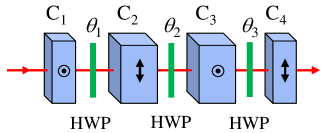
In this work, we study the depolarizing configuration of four fixed birefringent crystals with three half-wave plates (HWP) in between them (See Fig. 1). The lengths of and are twice the lengths of and . The fast axes of and , and the slow axes of and are parallel, and define the zero angle of the wave plates. The first and the third HWP angles are related by . The second HWP angle is tunable, and controls the depolarization process.
We have found that this configuration does not introduce additional rotations, except for reflections along the and the axes. These reflections can be compensated for by an additional half-wave plate at a zero angle before or after the setup. As there are no additional rotations, the radii of the mapped ellipsoids are aligned along the axes of the coordinate system. The radii dependence on the HWP angles is:
| (3) |
Two radii are always equal. Negative values correspond to a reflection along the corresponding radius direction. The possible channels with this configuration are depicted in Fig. 2. The requirement that the process matrix should have eigenvalues between 0 and 1, that sum up to 1, dictates that physically possible radii can not reside in the dark green zones Karpinski ; King01 . By examining the parameter space of and it can be shown that our configuration can create any channel within the yellow zone. When , the configuration has no effect on the initial state (all radii are equal to 1). The configuration of two identical crystals, as reported in Refs. Shaham and Shaham_QPT , creates channels along the white dashed line. The configuration presented here reproduces the two crystal scheme when or . The dephasing channel is represented by the line .
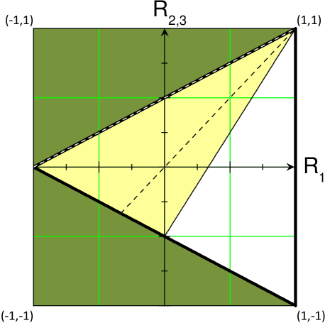
From Eqs. Realizing a variable isotropic depolarizer it can be shown that isotropic depolarization (i.e., ) is achieved when the first HWP is fixed at an angle of , or at an angle of . These isotropic channels are represented by the black dashed line in Fig. 2. The dependence of the degree of polarization on the angle in this case is:
| (4) |
For , no depolarization occurs, while for , the depolarization is complete.
We built this depolarizer with and performed QPT for angles in the range . Photon pairs were generated by spontaneous parametric down-conversion of 390 nm pulses. One photon of the pair was probabilistically split by a beam splitter, and sent to a single-photon detector (SPD). The second photon was sent to the depolarizer. Before entering the depolarizing unit, the photons were spectrally filtered by a 5 nm band-pass filter and spatially filtered by coupling them into a single-mode fiber, and then collimated into free space. The photons were prepared in the polarization states , , , and , which served as the initial states for the QPT procedure. The depolarizer was made of Calcite crystals that were 2 mm and 1 mm long. After depolarization, the final polarization state was characterized at the QST unit which was composed of half- and quarter-wave plates, a polarizer and another SPD. Detecting the two photons in coincidence reduced the background counts.
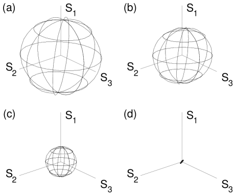
Experimentally measured processes at four angles are shown in Fig. 3. The four measured maps in the Poincaré sphere representation, were taken at values of and , which correspond to theoretical final values of of 0.97, 2/3, 0.36, and 0, respectively. All processes were reconstructed using the same maximal likelihood protocol that was previously used in Ref. Shaham_QPT , in order to restrict their parameters to physically allowed values.
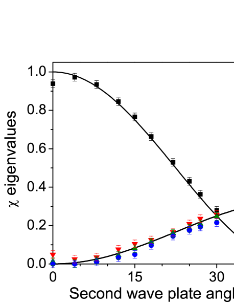
In order to test the isotropy of the constructed channels, the eigenvalues of the process matrix were studied. Figure 4 shows the measured eigenvalues of the reconstructed four-dimensional matrices as a function of the second HWP angle . All the measured eigenvalues are in good agreement with their theoretical predictions. In particular, three of the four eigenvalues have similar values. For angles close to zero, which represent processes of almost no depolarization, the highest eigenvalue deviates the most from theory. This is a result of the maximal likelihood procedure correction for negative eigenvalues which should be zero or positive-but-small.
Controllable isotropic depolarization can also be realized with other setup parameters. The main constraint on the respective crystal lengths is that and in order for zero depolarization to be possible. Surprisingly, the ratio can be any number (even less than 1) except for exactly 1 or 1/2. The demand for full temporal mode separation requires that satisfies Eq. 1. If the light has a relatively long coherence length, the birefringent crystals can be replaced by polarization preserving birefringent fibers, which can induce much higher temporal separation due to their length.
The depolarizer can even be built without any wave plates. The effect of a wave plate that is oriented in a certain angle can also be achieved by rotating all proceeding elements by an angle of . Thus, setting the two middle crystals and at an angle of or relative to the configuration of Fig. 1 is equivalent to the zero depolarization setting. Then, the amount of depolarization is controlled by applying a relative rotation between the left ( and ) and the right ( and ) pairs of crystals. Complete depolarization is reached when this rotation is set to . Note that such a configuration will result in additional polarization rotations.
In conclusion, we have described and demonstrated a controlled isotropic depolarizer. The depolarizer reduces the degree of polarization of any input polarization state by the same extent, to any required level. The depolarizer is composed of four fixed birefringent crystals and three half-wave plates. It is suitable for light of short coherence length. The induced depolarization was characterized using a quantum process tomography procedure. High fidelity with the theoretical predictions was observed. This depolarizer can also be realized without wave plates and the crystals can be replaced by birefringent fibers for light with longer coherence length. A possible application of this depolarizer is the realization of controlled quantum noise in photonic quantum communication channels in order to test quantum communication protocols.
We would like to thank the Israeli Ministry of Science and Technology for financial support.
References
- (1) K. Böhm, P. Marten, K. Petermann, E. Weidel, and R. Ulrich, ”Low-drift fibre gyro using a superluminescent diode,” Electron. Lett. 17, 352 (1981).
- (2) J. S. Wang, J. R. Costelloe, and R. H. Stolen, ”Reduction of the Degree of Polarization of a Laser Diode with a Fiber Lyot Depolarizer,” IEEE Photon. Technol. Lett. 11, 1449 (1999).
- (3) B. Lyot, ”Recherches sur la polarisation de la lumière des planètes et de quelques substances terrestres, Annales de l’Observatoire d’astronomie physique de Paris (Meudon) 8, 102 (1929).
- (4) K. Mattle, H. Weinfurter, P. G. Kwiat, and A. Zeilinger, ”Dense Coding in Experimental Quantum Communication,” Phys. Rev. Lett. 76, 4656 (1996).
- (5) N. Gisin, G. Ribordy, W. Tittel, and H. Zbinden, ”Quantum cryptography,” Rev. Mod. Phys. 74, 145 (2002).
- (6) P. G. Kwiat, A. J. Berglund, J. B. Altepeter, and A. G. White, ”Experimental Verification of Decoherence-Free Subspaces,” Science 290, 498 (2000).
- (7) G. Puentes, D. Voigt, A. Aiello, and J. P. Woerdman, ”Tunable spatial decoherers for polarization entangled photons,” Opt. Lett. 31, 2057 (2006).
- (8) M. P. Almeida, F. de Melo, M. Hor-Meyll, A. Salles, S. P. Walborn, P. H. S. Ribeiro, and L. Davidovich, ”Environment-induced sudden death of entanglement,” Science, 316, 579 (2007).
- (9) M. Karpiński, C. Radzewicz, and K. Banaszek, ”Fiber-optic realization of anisotropic depolarizing quantum channels,” J. Opt. Soc. Am. B 25, 668 (2008).
- (10) A. Shaham and H. S. Eisenberg, ”Realizing controllable depolarization in photonic quantum information channels,” Phys. Rev. A 83, 022303 (2011).
- (11) A. Chiuri, V. Rosati, G. Vallone, S. Pa’dua, H. Imai, S. Giacomini, C. Macchiavello, and P. Mataloni, ”Experimental Realization of Optimal Noise Estimation for a General Pauli Channel,” Phys. Rev. Lett. 107, 253602 (2011).
- (12) J. B. Altepeter, E. R. Jeffrey, and P. G. Kwiat, ”Photonic state tomography,” Adv. At. Mol. Opt. Phys. 52, 105 (2005).
- (13) I. L. Chuang and M. A. Nielsen, ”Prescription for experimental determination of the dynamics of a quantum black box,” J. Mod. Opt. 44, 2455 (1997).
- (14) A. Shaham and H. S. Eisenberg, Phys. Scr. T 147, 014029 (2012).
- (15) C. King and M. B. Ruskai, ”Minimal entropy of states emerging from noisy quantum channels,” IEEE Trans. Inf. Theory 47, 192 (2001).