Polarization modulation time-domain terahertz polarimetry
C. M. Morris, R. Valdés Aguilar, A. V. Stier, N. P. Armitage
Department of Physics and Astronomy, The Johns Hopkins University, 3400 N. Charles St., Baltimore, MD 21218
Abstract
We present high precision measurements of polarization rotations in the frequency range from 0.1 to 2.5 THz using a polarization modulation technique. A motorized stage rotates a polarizer at Hz, and the resulting modulation of the polarization is measured by a lock-in technique. We achieve an accuracy of (900 rad) and a precision of (350 rad) for small rotation angles. A detailed mathematical description of the technique is presented, showing its ability to fully characterize elliptical polarizations from 0.1 to 2.5 THz.
OCIS codes: (300.6495) Spectroscopy, terahertz; (260.5430) Polarization; (120.2130) Ellipsometry and polarimetry
References and links
- [1] M. Tonouchi, “Cutting-edge terahertz technology,” Nature Photonics 1, 97 (2007).
- [2] M. Nuss and J. Orenstein, “Terahertz time-domain spectroscopy” in Millimeter and Submillimeter Wave Spectroscopy of Solids, George Grüner, ed., (Springer Berlin / Heidelberg, 1998), Topics in Applied Physics 74, 7–50.
- [3] M. S. Sherwin, C. A. Schmuttenmaer, and P. H. Bucksbaum, eds. “Opportunities in THz science,” DOE-NSF-NIH Workshop, Feb. 12-14, 2004, .
- [4] R. A. Kaindl, M. A. Carnahan, D. Hägele, R. Lövenich, and D. S. Chemla, “Ultrafast terahertz probes of transient conducting and insulating phases in an electron-hole gas,” Nature 423, 734 (2003).
- [5] J. N. Heyman, R. Kersting, and K. Unterrainer, “Time-domain measurement of intersubband oscillations in a quantum well,” Appl. Phys. Lett. 72, 644–646 (1998).
- [6] A.J. Gatesman, J. Waldman, M. Ji, C. Musante, and S. Yagvesson, “An anti-reflection coating for silicon optics at terahertz frequencies,” Microwave and Guided Wave Letters, IEEE 10, 264–266 (2000).
- [7] L. S. Bilbro, R. Valdés Aguilar, G. Logvenov, O. Pelleg, I. Bozovic, and N. P. Armitage, “Temporal correlations of superconductivity above the transition temperature in probed by terahertz spectroscopy,” Nature Physics 7, 298–302 (2011).
- [8] J. Corson, R. Mallozzi, J. Orenstein, J. N. Eckstein, and I. Bozovic, “Vanishing of phase coherence in underdoped ,” Nature 398, 221 (1999).
- [9] S. Wang, B. Ferguson, D. Abbott, and X.-C. Zhang, “T-ray imaging and tomography,” Journal of Biological Physics 29, 247–256 (2003).
- [10] M. Nagel, P. H. Bolivar, M. Brucherseifer, H. Kurz, A. Bosserhoff, and R. Büttner, “Integrated planar terahertz resonators for femtomolar sensitivity label-free detection of dna hybridization,” Appl. Opt. 41, 2074–2078 (2002).
- [11] B. B. Hu and M. C. Nuss, “Imaging with terahertz waves,” Opt. Lett. 20, 1716–1718 (1995).
- [12] X-C Zhang, “Terahertz wave imaging: horizons and hurdles,” Physics in Medicine and Biology 47, 3667 (2002).
- [13] J. L. Johnson, T. D. Dorney, and D. M. Mittleman, “ Enhanced depth resolution in terahertz imaging using phase-shift interferometry,” Appl. Phys. Lett. 78, 835–837 (2001).
- [14] E. Castro-Camus, “Polarization-resolved terahertz time-domain spectroscopy,” Journal of Infrared, Millimeter and Terahertz Waves, 1–13 (2011).
- [15] R. Shimano, Y. Ikebe, K. S. Takahashi, M. Kawasaki, N. Nagaosa, and Y. Tokura, “Terahertz Faraday rotation induced by an anomalous Hall effect in the itinerant ferromagnet ,” Europhysics Letters 95, 17002 (2011).
- [16] A. Kapitulnik, J. S. Dodge, and M. M. Fejer, “High-resolution magneto-optic measurements with a sagnac interferometer,” Journal of Applied Physics 75, 6872–6877 (1994).
- [17] J. Xia, Y. Maeno, P. T. Beyersdorf, M. M. Fejer, and A. Kapitulnik, “High resolution polar kerr effect measurements of : Evidence for broken time-reversal symmetry in the superconducting state,” Phys. Rev. Lett. 97, 167002 (2006).
- [18] E. Castro-Camus, J. Lloyd-Hughes, M. B. Johnston, M. D. Fraser, H. H. Tan, and C. Jagadish, “Polarization-sensitive terahertz detection by multicontact photoconductive receivers,” Appl. Phys. Lett. 86, 254102 (2005).
- [19] H. Makabe, Y. Hirota, M. Tani, and M. Hangyo, “Polarization state measurement of terahertz electromagnetic radiation by three-contact photoconductive antenna,” Opt. Express 15, 11650–11657 (2007).
- [20] M. Neshat and N. P. Armitage, “Improved measurement of polarization state in terahertz polarization spectroscopy,” In press, Optics Letters (2012).
- [21] X.-L. Qi, T. L. Hughes, and S.-C. Zhang, “Topological field theory of time-reversal invariant insulators” Phys. Rev. B 78, 195424 (2008).
- [22] R. Nandkishore, L. S. Levitov, and A. V. Chubukov, “Chiral superconductivity from repulsive interactions in doped graphene,” Nature Physics 8, 158–163 (2012).
- [23] W.-K. Tse and A. H. MacDonald, “Magneto-optical Faraday and Kerr effects in topological insulator films and in other layered quantized Hall systems,” Phys. Rev. B 84, 205327 (2011).
- [24] J. Maciejko, X.-L. Qi, H. D. Drew, and S.-C. Zhang, “Topological quantization in units of the fine structure constant,” Phys. Rev. Lett. 105, 166803 (2010).
- [25] J. Shan, J. I. Dadap, and T. F. Heinz, “Circularly polarized light in the single-cycle limit: The nature of highly polychromatic radiation of defined polarization,” Opt. Express 17, 7431–7439 (2009).
- [26] C. Bernhard, J. Humlıcek, and B. Keimer, “Far-infrared ellipsometry using a synchrotron light source-the dielectric response of the cuprate high superconductors,” Thin solid films 455, 143–149 (2004).
- [27] M. Grayson, L. B. Rigal, D. C. Schmadel, H. D. Drew, and P.-J. Kung, “Spectral measurement of the Hall angle response in normal state cuprate superconductors,” Phys. Rev. Lett. 89, 037003 (2002).
- [28] G. S. Jenkins, D. C. Schmadel, and H. D. Drew, “Simultaneous measurement of circular dichroism and Faraday rotation at terahertz frequencies utilizing electric field sensitive detection via polarization modulation,” Review of Scientific Instruments 81, 083903 (2010).
- [29] R. Valdés Aguilar, A. V. Stier, W. Liu, L. S. Bilbro, D. K. George, N. Bansal, L. Wu, J. Cerne, A. G. Markelz, S. Oh, N. P. Armitager, “Thz response and colossal kerr rotation from the surface states of the topological insulator Bi2Se3,” Physical Review Letters 108, 087403 (2012).
- [30] D. K. George, A. V. Stier, C. T. Ellis, B. D. McCombe, J. Černe, and A. G. Markelz, “Terahertz Magneto Optical Polarization Modulation Spectroscopy,” arXiv:1201.2701v1 [cond-mat.mtrl-sci] (2012).
- [31] C. Huang, S. Zhao, H. Chen, and Z. Liao, “Attenuation characterization of multiple combinations of imperfect polarizers,” J. Opt. Soc. Am. A 27, 1060–1068 (2010).
- [32] L. Ren, C. L. Pint, T. Arikawa, K. Takeya, I. Kawayama, M. Tonouchi, R. H. Hauge, and J. Kono, “Broadband terahertz polarizers with ideal performance based on aligned carbon nanotube stacks,” Nano Letters, 12, 787 (2012).
- [33] H. Fujiwara, “Spectroscopic Ellipsometry: Principles and Applications,” (John Wiley & Sons, Ltd., 2006).
- [34] M. Born and E. Wolf, “Principles of Optics,” (Cambridge University Press, 1997).
- [35] J.-B. Masson and G. Gallot, “Terahertz achromatic quarter-wave plate,” Opt. Lett. 31, 265–267 (2006).
Picosecond ( s) timescales are one of the most ubiquitous in condensed matter systems. Scattering times of electrons in metals, resonant periods of electrons in semiconductors and their nanostructures, vibrational frequencies of molecular crystals, superconducting “Cooper pair” decoherence times, lifetimes of collective vibrations in biologically important proteins, and even electron transit times in Intel’s THz transistor are all phenomena occurring in the picosecond range. Such ubiquity makes measurement tools employing terahertz ( cycles/sec) electromagnetic radiation potentially quite useful. Unfortunately, measurements in the terahertz (THz) spectral range have traditionally been challenging to implement as they lie in the so-called “terahertz gap” - the range of frequencies above the capabilities of traditional electronics, but below that of optical generators and detectors (photonics). In recent years, however, a number of dramatic advances in the form of time-domain THz spectroscopy (TDTS) have helped span this gap, creating an emerging area of optical and materials research, with a broad range of applications [1, 2].
Photoconductive switch based TDTS works by sequential excitation of source and detector semiconductor (GaAs in the present work) structures by a femtosecond pulsed laser. Laser excitation of a biased Auston switch THz emitter creates an approximately electromagnetic pulse (with THz frequency Fourier components) that propagates through space and interacts with a sample under test. Detection is accomplished via another photoexcited Auston switch, which is biased across its electrodes by the transient THz electric field. With these developments, THz spectroscopy has become a tremendous growth field [3], finding potential use in a multitude of areas including materials characterization for solid-state devices [4, 5], optimization of the electromagnetic response of novel coatings [6], probes of superconductor properties [7, 8], security applications for explosives and biohazard detection [9], the detection of protein conformational changes [10], and non-invasive structural and medical imaging [11, 12, 13].
Despite the advances in THz spectroscopy, a number of challenges remain. For example, highly accurate measurement of polarization states in the THz range has proven to be difficult [14]. Historically the highest achievable precisions in the THz or millimeter wave range have been approximately , measured using rotatable wire grid polarizers, with higher precisions only being achieved with extremely specialized setups [15]. This is nowhere near the sub-rad resolution that is possible in the near infrared and visible range [16, 17]. A number of groups have developed polarization sensitive switches [18, 19] fabricated in a multi-pole configuration, where a single device is sensitive to two orthogonal electric field polarizations. This simultaneous detection of both electric field polarizations is advantageous, as the phase sensitive nature of TDTS means that unlike conventional polarimetry, only two orthogonal directions have to be measured to resolve the complete Jones matrix for a polarized wave.
Although multi-pole devices [18, 19] and calibrated wire-grid polarizer measurements [20] are capable of angular precision of 0.2-0.3∘, one might hope for even higher angular precision, as many material systems exhibit very small Kerr or Faraday rotations that are of fundamental interest for condensed matter physics [17, 21, 22, 23, 24]. The possibility of even higher precision THz polarimetry would also open the door for entirely new spectroscopic techniques such as THz ellipsometry [25]. Currently the best THz ellipsometers (based on continuous wave sources) cannot take reliable data below THz [26].
With these ends in mind we have investigated and applied a polarization modulation technique using a fast rotator in combination with photoconductive switch based time-domain THz spectroscopy . This technique, originally developed for use with continuous wave gas lasers and Fourier transform infrared spectroscopy [27, 28], shows a distinct advantages when applied to TDTS, namely that the phase sensitivity of TDTS allows the unambiguous measurement of the Jones vector polarization of a THz wave. The technique has recently been applied to TDTS using electro-optic detection on topological insulators [29, 30]. We find that when used with photoconductive switch TDTS it is capable of an unprecedentedly high angular precision of better than , with an accuracy of in the frequency range from 0.1 to 1.25 THz, a sensitivity that makes entirely new classes of measurements possible. In this paper we lay out the mathematical analysis of a polarization modulation measurement and describe initial experimental characterizations of this technique.
1 Theory
In this technique, a rotating polarizer is used to modulate the polarization state of the terahertz light. In a manner to be described below, it allows for direct detection of the vertical () and horizontal () components of the electric field after passing through a sample using the in-phase and out-of-phase channels of a lock-in amplifier, respectively. The advantage of this technique is three-fold. First, measurement time is reduced as a single measurement determines both electric field polarization states, compared to the two measurements required with static polarizers. Second, because the two polarization channels are measured simultaneously, time dependent common mode noise may be ratioed out, improving the signal of measurements such as Kerr and Faraday spectroscopies. Third, as the experiment is only sensitive to the modulation of the polarization state, many detrimental effects due to the finite extinction ratio of the analyzing polarizers cancel out, improving the accuracy of the measurement.
We first describe the mathematical analysis in detail. As usual, a time-domain pulse can be written as a superposition of Fourier components
| (1) |
Here, is the purely real electric field propagating through the system, and describes the amplitude of the complex Fourier components that comprise .The mathematical description of the pulse as it propagate through the system is easiest to perform in terms of these Fourier components. The propagation of the Fourier components as they travel through the system can be described with the Jones matrix formalism. In this formalism a matrix with (in general) complex elements acts on the Fourier component with electric field amplitude to produce a final polarization state :
| (2) |
The advantage of this formalism is that a complicated series of optical elements can be represented as a simple set of matrix multiplications on the original electric field Fourier component.
The Jones matrix for a polarizer with its transmission axis oriented at an angle with respect to the axis is given by:
| (3) |
Here, a polarizer with polarizes light in the direction and is denoted , and a polarizer with is called . For a rotating polarizer with angular velocity , the angle is simply replaced by the factor to obtain the polarizer matrix as a function of time.
In general, the goal of ellipsometry is to determine the values of the complex elements of the Jones transfer matrix for a sample. The changes in amplitude and phase these elements produce in the electric field can then be correlated with physical properties of the sample, such as the conductivity. The complex transfer matrix for a sample is represented as:
| (4) |
In the setup described here, a rotating polarizer is used to modulate the polarization of a terahertz waveform after it has passed through the sample (Fig. 1). Analysis of the time dependence of the waveform can be used to extract the frequency dependent components of the matrix.
Using the Jones matrices to describe the frequency domain Fourier components of the waveform as they travel through the sample and rotator, the result is:
| (10) | |||||
These electric fields have a mixed dependence on the components of the matrix. The analysis can be greatly simplified by adding vertical polarizers before and after the rotator and sample, respectively, (Fig. 1) to isolate and :
| (11) | |||||
or alternatively adding horizontal polarizers to isolate and :
| (12) | |||||
Note that photoconductive antennas themselves have polarization sensitivity and naturally the best results will be obtained if they are oriented along the direction defined by the static polarizers.
To understand the detection of the waveforms by the photoconductive antennas, there are two relevant times to keep track of in the experiment. First, there is the time associated with the position of the delay stage (Fig. 1), determining the small time window of the terahertz pulse that is being measured. We denote this time as . This is connected to the position of the delay stage by . Second, there is the time associated with the rotation of the polarizer, denoted as . This is the time that is referred to in Eqs. (11) and (12). We can now rewrite Eq. (1) for the purely real electric field measured at the detector using this notation:
| (13) |
where is defined in Eq. (11). In the lock-in amplifier this signal is then mixed with the second harmonic of and integrated for an amount of time determined by the lock-in time constant, . The signal of the in-phase lock-in channel is given by
| (14) | |||||
Taking the Fourier transform of allows the Fourier components to be extracted:
| (15) | |||||
Substituting in for from Eq. (11):
| (16) | |||||
where parameterizes the combined responsivity of the antenna and lock-in amplifier. In the channel of the lock-in the signal is mixed with , and similarly gives:
| (17) |
How do these measured values relate to the quantities we wish to measure, namely the electric fields after the sample? An analysis of the effect of the sample on vertically polarized light without the rotator shows that the electric fields after the sample are:
| (18) |
Comparing the results of Eqs. (16) and (17) with the fields found in Eq. (18), it is apparent that the rotator measurement is equivalent to direct measurement of the x and y components of the electric field after the sample simultaneously in the two lock-in channels. Eqs. (16) and (17) represent the principle result of this analysis: that a single measurement with the rotator technique is exactly equivalent to two measurements with a standard static polarizer setup.
In a real system, the non-ideality of the components must be taken into account. For example, perfectly aligned off-axis parabolic mirrors produce no rotation of the polarization state, but in a real system perfect alignment is impossible to achieve. In this regard placement of optical elements in the setup is crucial. In Fig. 1 off-axis parabolic mirrors (OAPs) 1 and 2 can introduce a rotation of the initial polarization state of the electric field from the emitter. To eliminate measurement errors introduced by this rotation, it is critical to place the first static polarizer after OAPs 1 and 2, which essentially redefines the initial vertical electric field for the measurement at this point.
For OAPs 3 and 4 the same problem exists. Consider the situation explicitly if polarizer P2 is placed not immediately before OAP 3, but instead after OAP 4. The total rotation produced from small misalignments in OAPs 3 and 4 can be represented by the rotation matrix:
| (19) |
The polarized light detected in the two channels of the lock-in becomes a mixture of the components of the matrix:
| (20) |
As before, placing a polarizer between the rotator and OAP 3 simplifies the result:
| (21) |
Now each channel acquires the same rotation factor of , which merely acts to scale the overall magnitude of the electric field. There is no mixing of the polarization states in the lock-in channels.
The finite extinction ratio of the polarizers in the system is also a factor in the overall system performance. The Jones matrix for an imperfect polarizer is [31]:
| (22) |
where is the extinction ratio of the polarizer, defined as the ratio of the transmitted electric field when the polarizer transmission axis is perpendicular and parallel to the electric field direction, . Accounting for the finite extinction ratio () of the rotating polarizer in the Jones matrix analysis, the measured signals become:
| (23) |
The finite extinction ratio of the rotating polarizer acts only as a simple scaling of the amplitude of the measured electric field. This highlights a distinct advantage of the modulation technique over the standard static polarizer measurements: only modulated signals are measured by the lock-in, and non-ideality of the rotating polarizer only produces a small effect on the amplitude of the measured electric fields. Commercially available polarizers in this frequency range typically have extinction ratios of , resulting in only difference between the ideal and real signals. The best figure of merit for the rotating polarizer becomes its stability under rotation and its robustness to high rotation rates to reduce noise, not the extinction ratio.
Finally, the effects of the finite extinction ratios of the static polarizers must be considered. This changes the form of the vertical polarization matrix, , to
| (24) |
Finite extinction ratios of the static polarizers mix different matrix components in the measured signals. Since the rotator projects the electric field onto the second polarizer at large angles, a non-trivial electric field leakage results and the elements of the matrix are mixed in the two detection channels. The obvious solution is to increase the quality of polarizer, but while polarizers with significantly higher extinction ratios in the terahertz range have been demonstrated, they are still not at the stage of commercial production [32]. As shown below the solution to this problem relies on the final analysis performed on the collected time domain waveforms.
As described above, in order to obtain the electric field components as a function of frequency, the measured time domain waveform is Fourier transformed to obtain the frequency response. For many measurements performed in this system, the quantity of interest is the rotation angle introduced by the sample, which can be found by simply taking the ratio of the Fourier transforms of and . For the case of vertical P1 and P2 polarizers (Eq. (16)):
| (25) |
If the polarizers are assumed to be ideal, simple cases such as rotation can be explicitly solved. The T matrix for a rotation is given by Eq. (19), which allows Eq. (25) to take a simple form
| (26) |
which easily gives the rotation angle
| (27) |
However a finite extinction ratio of the polarizers complicates Eq. (25). If the finite extinction ratio of the static polarizers in the geometry is taken into account, it is impossible to solve Eq. (27) analytically for the rotation. The situation is particularly complicated for the case where small misalignments in off-axis parabolic mirrors given finite angles and . However, we can perform a Taylor expansion in up to second order for a simple rotation, giving
| (28) | |||||
This expansion shows that a single measurement is in general not sufficient to determine the rotation angle. Even with the setup optimized by proper polarizer placement to eliminate first order rotation effects due to the off-axis parabolic mirrors ( and ) (as discussed above), the finite extinction ratio of the polarizers can still cause systematic error. Note however, that the second term in Eq. (28) does not depend on the rotation angle . In this regard, two methods can be used to eliminate the systematic error. If the sample itself can be used to give a reference angle of rotation (say at a particular temperature or magnetic field), this reference can be subtracted to eliminate the constant term in Eq. (28) and obtain the relative change in rotation angle. An example could be comparing a rotation measurement above and below in a superconductor for evidence of time reversal symmetry breaking [17] or of a magnetic material above and below a magnetic ordering temperature. Alternatively, if an accurate reference sample can be used, the sample and reference angle scans can be subtracted, and systematic errors of this kind can be eliminated. Also note that in general the contribution of will be small, as in the typical experimental geometry the vertically oriented photoconductive switches give an electric field which is primarily oriented along the direction.
Up to this point, a technique has been developed and shown to be capable of measuring simple rotations. What are the ultimate capabilities of this technique, and how do they connect to full terahertz ellipsometry measurements? To answer this question, we must first define what is measured in a standard ellipsometric measurement. In standard ellipsometry, light with a known polarization is focused onto a sample, and the reflected or transmitted light is collected by polarization sensitive detectors. The amplitude of the light in the and axes is determined as a function of the frequency from this measurement.
| (29) |
where and represents the temporal phase difference between the two field components [33]. The broadband polarization modulation measurement presented here gives and , so both and can be calculated and a full frequency dependent ellipsometry measurement is possible.
Next we can ask, how do these measured complex field components connect to rotations and the ellipticity? In general, fully polarized states of monochromatic transverse electromagnetic waves trace out an ellipse in time with major () and minor () axes, each at an angle with the and axes in the laboratory frame, respectively [33]. The ellipticity is defined by the major and minor axes as . For example, for circularly polarized light and with + for right circular polarization, and - for left. Linearly polarized light is characterized by and . All other polarization states are called elliptical. For the simple polarizer in Eq. (27), the ellipticity , and the angle corresponds exactly to the angle of rotation .
To perform a complete analysis, it is important to note [34] that the ellipse the electric field traces in time is related to the measured ellipsometric quantities and by
| (30) | |||||
| (31) |
To start the analysis, we take defined in Eq. (29), which can then be expanded
| (32) | |||||
First taking the real part of Eq. (32) we find
| (33) | |||||
| (34) |
which is simply the rotation angle that was found for the simple polarizer case. Now we find the imaginary part of Eq. (32).
| (35) | |||||
Using Eq. (31) we can simplify:
| (36) |
The can be used to determine the the ellipticity . This analysis shows that the complex angle extracted from contains all the information necessary to determine the frequency dependent elliptical polarization state of the final terahertz electric field. The real part is a direct measurement of the rotation angle of the light, and the imaginary part determines the ellipticity of the final electric field. In fact, this analysis does not rely on the polarization modulation technique, but is valid for the static measurement described by Eq. (18) as well. The advantage of the polarization modulation technique is that the full characterization of the frequency dependent electric field ellipse can be extracted from a single measurement. This shows the power of measuring the time dependent electric field and collecting the full amplitude and phase information of the waveform.

2 Experiment


The experimental setup is shown in Fig. 1. The generation and detection of the terahertz waveform is accomplished by a standard time-domain terahertz spectrometer using photoconductive antennas. A fs pulse from a KM Labs Ti:Sapph oscillator with an 80 MHz repetition rate is split into two paths via a beamsplitter. The first pulse strikes a biased photoconductive antenna, generating a terahertz waveform with a spectral bandwidth from 0.1 to 3 THz. The OAPs are laid out in an geometry. OAPs 1 and 2 are used to collimate and focus the waveform. A wire grid polarizer (P1) after OAP 2 defines the initial vertical polarization state of the system as the terahertz light is focused onto the sample. The vertically polarized light passes through the sample, where it becomes elliptically polarized according to the sample transfer () matrix. The elliptically polarized terahertz light passes through a rotating wire-grid polarizer (RP), made by QMC Instruments, which modulates the elliptical polarization at a frequency . A second vertical polarizer (P2) projects the rotated light back to the vertical () axis, and a pair of off-axis parabolic mirrors recollimate and focus the terahertz light onto the detector antenna. The second pulse created by the beamsplitter is used for detection of the waveform. An additional vertical polarizer (P3) is used to account for any rotations produced by OAPs 3 and 4, as the antenna has a small, but finite response for the horizontal polarization, which would result in mixing of the elements of the matrix in the detection as shown above. The terahertz electric field at the antenna produces a small AC current, and a transimpedance amplifier is used to convert this to a voltage. The voltage signal is detected by an SRS 830 lock-in amplifier, where it is mixed with the second harmonic of the rotation frequency . The rotation frequencies used here (2 between 50 Hz and 80 Hz) are chosen to be high enough to significantly reduce noise, but small enough to minimize the possibility of damaging the polarizer.
The rotator was built by the Instrument Development Group in the Johns Hopkins Department of Physics and Astronomy. The polarizer is held by a 2” aluminum cylinder that can be rotated at high speeds using Bearing Works silicon nitride ball bearings. This is connected via a belt drive to a high speed AC motor, the Faulhaber Minimotor 4490, which has a variable speed controller that can be used to rotate the polarizer up to 2 = 200 Hz (6000 rpm). To generate a trigger signal for the lock-in, two small holes are drilled in the rotating cylinder, and an LED and photodiode are placed on opposite sides of the cylinder. When a hole passes the LED, it triggers the photodiode on the opposite side of the cylinder. This produces pulses at twice the rotation frequency, giving the 2 signal needed for the lock-in detection. All this is held in a metal casing that can be securely attached to the optical table to reduce detrimental effects caused by motor vibration.
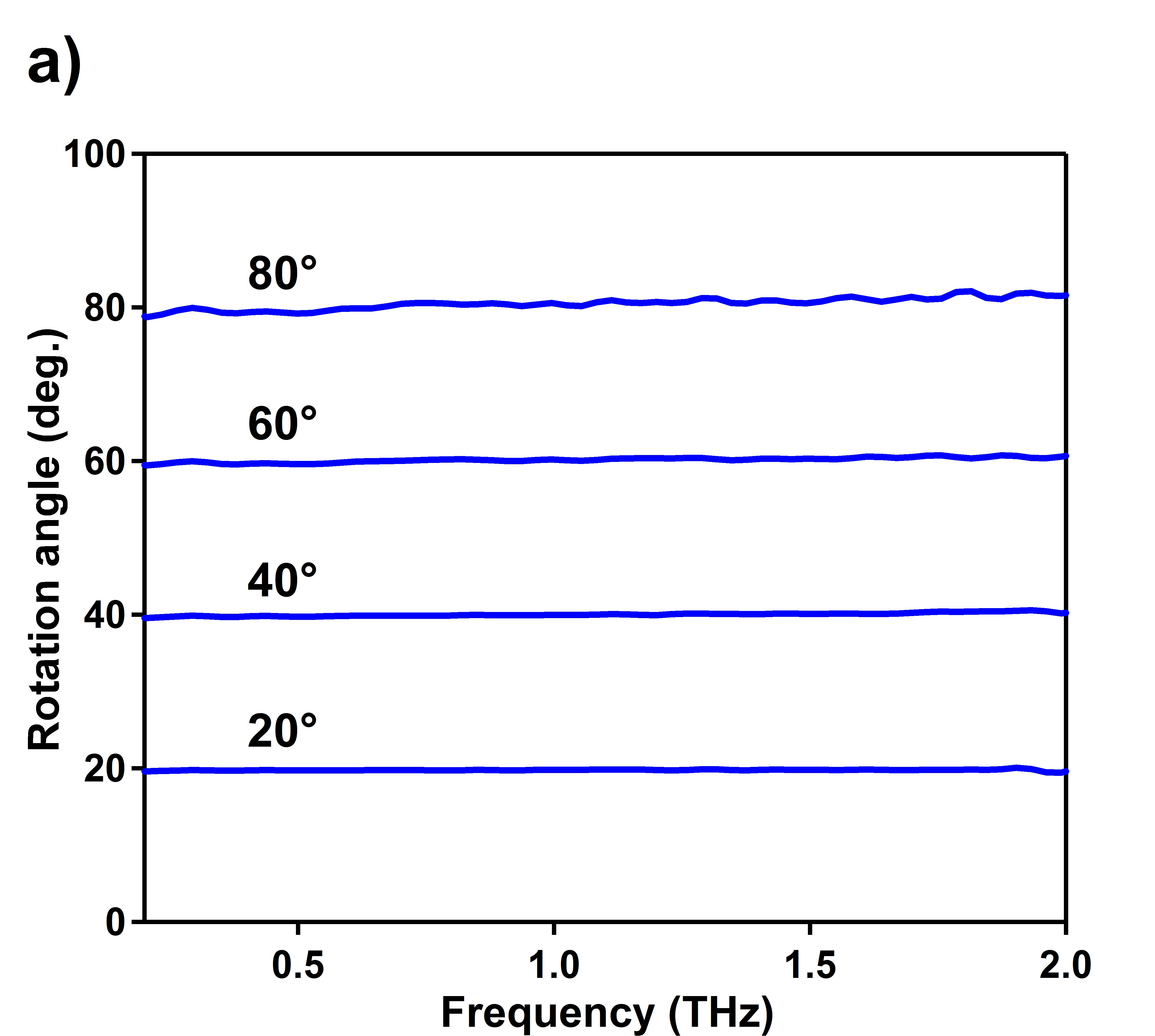
To characterize system performance, a wire-grid polarizer in a static rotation mount was used as a reference sample. To demonstrate the versatility of the technique, a number of polarizer angles were measured with the results shown in Fig. 2. For large rotation angles, the precision and accuracy of the measurement is reduced, as the comparison of the measurements for rotation angles of and (Fig. 2b) shows. This seeming loss of precision and accuracy has its origins in the non-ideality of the polarizer as a test sample. The polarizer does not simply rotate the polarization, but rather projects the polarization with an angle dependent () attenuation. For large angles, the sample polarizer significantly reduces the amplitude of the initial terahertz electric field, thereby decreasing the achievable signal to noise. The finite extinction ratio of the polarizers also becomes more important for larger polarizer angles, as the amplitude of the orthogonally polarized field transmitting through the polarizer grows. Additionally, at these large angles the amplitude of the orthogonal transmitted electric field becomes highly frequency dependent. These two effects are shown in detail in Fig. 2b. At , the measured angle is constant to within over the range from 0.1-1.75 THz, with a precision of . At , the angle is only constant to within the same frequency range, and the precision of the measurement is reduced to . The ideal test sample would be a broadband half waveplate that could rotate without attenuation. However, broadband terahertz waveplates are at the developmental stage [35], so a wire grid polarizer serves as the simplest available test sample.

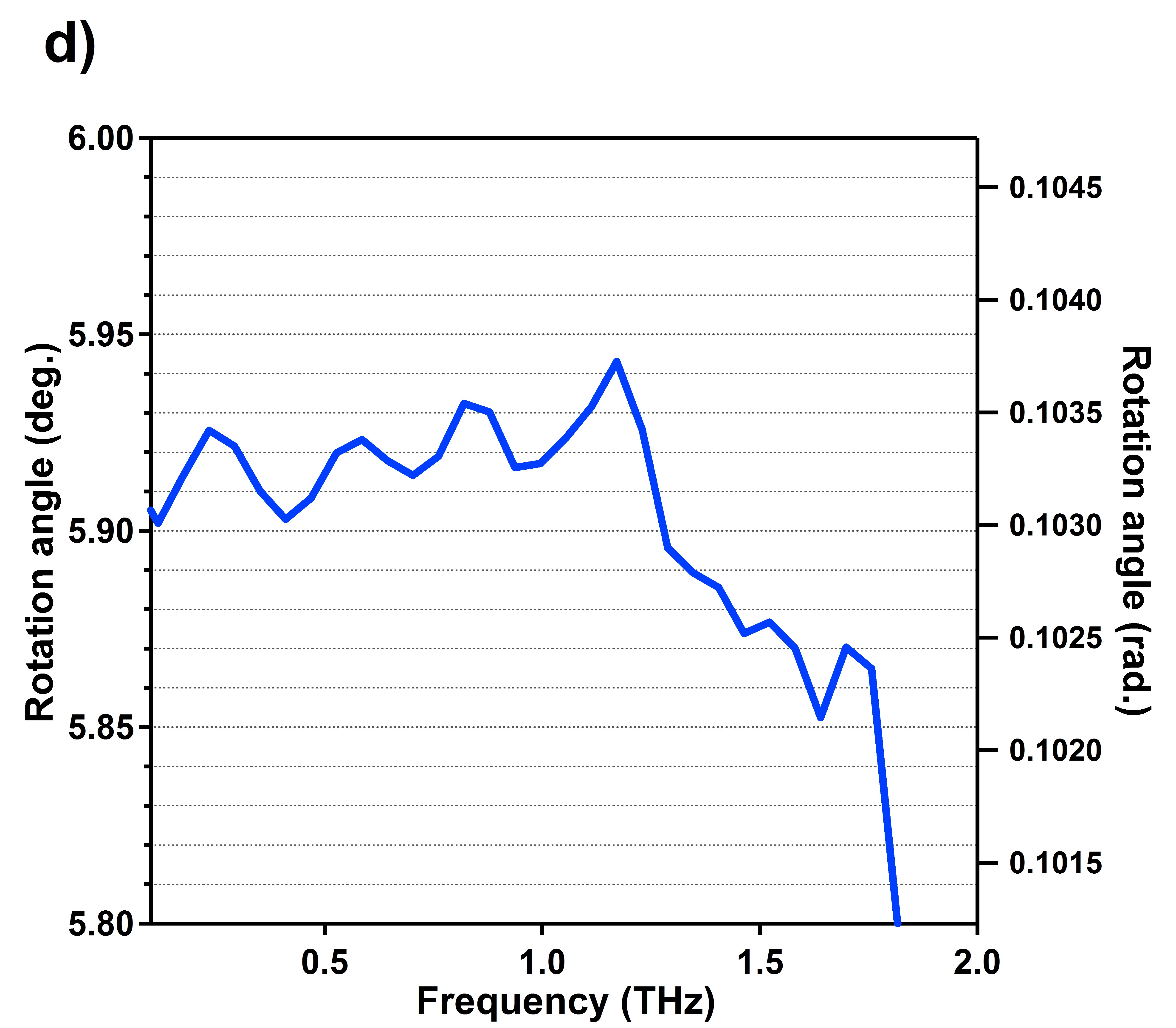
As demonstrated above, the accuracy and precision of the technique improve significantly for smaller rotation angles of the test polarizer. Fig. 2c shows a measurement for a polarizer angle of . For this small angle, within the range of 0.1-1.25 THz the measured angle is constant to within , and from the signal to noise ratio, we estimate that changes in the angle as small as (350 rad) can be resolved. The main limitation in measuring the accuracy of the technique is the difficulty in setting the angle of the test polarizer to the required level of accuracy. At this point we can measure THz polarization steps much more precisely that we can generate them. The precision of the system is thus far only limited by the averaging time. The scans shown in Fig. 2 each account for 20 minutes of measurement, which is reasonable for many experiments.
To test the technique on a real sample, the birefringent response of a piece of X-cut sapphire was measured. The sample was placed with the ordinary and extraordinary axes at with respect to the initial vertical () light polarization. This crystal orientation projects the electric field of the terahertz waveform equally on the two crystal axes, producing a phase delay between the two components and changing the polarization from linear to elliptical. For a purely birefringent material the matrix takes the form
| (37) |
where is the angle between the extraordinary axis and laboratory axis, and and are the additional phases associated with the electric field traveling along the extraordinary and ordinary axes, respectively. Here, with , Eq. (37) becomes
| (38) |
For the birefringent response, introducing , we find that
| (39) |
meaning the phase difference between the two axes is
| (40) |
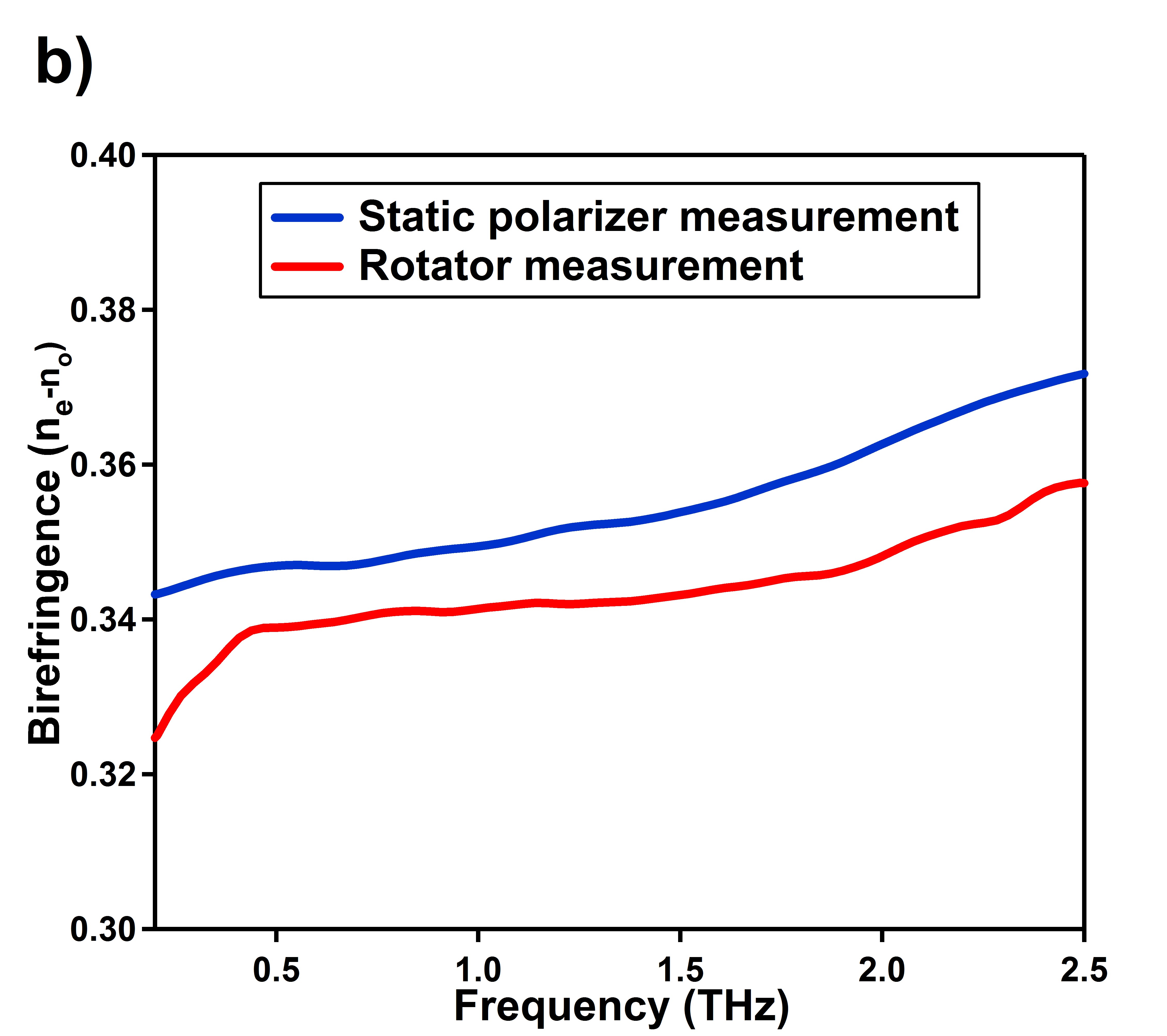
In Fig. 3a, we show a time-domain trace of the measured electric field amplitudes as a function of time, measured directly on the in-phase and out-of-phase channels of the lock-in amplifier. It shows quite readily the conversion of the initial linearly polarized THz pulse into an elliptically polarized state. From the Fourier transforms of the data and the phase difference between field components, the frequency dependent difference in the index of refraction between the ordinary and extraordinary axes can easily be computed using , where is the thickness of the sapphire. In Fig. 3b we compare the measured birefringence of the sapphire taken with the conventional technique using static wire grid polarizers and the rotator technique. For the static wire grid polarizer technique, the ordinary axis of the sapphire is oriented along the axis. A wire grid polarizer oriented at is placed before the sample, defining the incoming electric field polarization at to the ordinary and extraordinary axes. An analyzing polarizer is placed after the sample, and two measurements are done at . A quick mathematical analysis with the tools described above shows that the two measurements then give
| (41) |
thus taking the ratios of these two measurements yields the same result for as the rotator measurement.
Fig. 3b shows that the two measurements produce slightly different results. The difference in the two measurements is ascribed to the imperfect nature of the polarizers. For the fast rotator experiment, to second order the effects of the finite polarizer extinction ratios drop out. In the static experiment, analysis using the imperfect polarizer (Eq. 22) changes Eq. (41) such that and . The robustness of the polarization modulation technique actually produces a measurement that is less prone to error than that with the static polarizers. This simple measurement demonstrates the power of the technique: a single polarization modulation measurement produces the same information as three measurements with a static polarizer setup, and gives much improved accuracy and precision.
In conclusion, we have demonstrated high precision measurement of polarization states using time domain terahertz spectroscopy. We can resolve angular rotations with an accuracy of and a precision of . Additionally, a number of practical mathematical results useful in the analysis of phase sensitive polarization measurements have been presented. We believe that this technique will have a wide applicability to a number of materials systems at the forefront of condensed matter physics, such as high-Tc superconductors, quantum magnets, and topological insulators.
Acknowledgements
The authors would like to thank J. Orndorff of the Instrument Development Group in the Johns Hopkins Department of Physics and Astronomy for the development and construction of the fast rotator. The authors would also like to thank M. Neshat, A. Marklez, J. Cerne, and G. Jenkins for helpful discussions. This work was made possible by support from the Gordon and Betty Moore Foundation and DARPA YFA N66001-10-1-4017