Field test of the wavelength-saving quantum key distribution network
Abstract
We propose a wavelength-saving topology of quantum key distribution (QKD) network based on passive optical elements, and report the field test of this network on the commercial telecom optical fiber. In this network, 5 nodes are supported with 2 wavelengths, and every two nodes can share secure keys directly at the same time. All QKD links in the network operate at the frequency of 20 MHz. We also characterized the insertion loss and crosstalk effects on the point-to-point QKD system after introducing this QKD network.
Quantum key distribution enables separate legitimate participants to share keys with provable unconditional security gisin02 . After last two decades of developments, the point-to-point (P2P) QKD, which only makes two separate parties to share secure keys, has matured sufficiently to provide a practical secure communication, some companies have developed their related commercial products. Furthermore, the QKD network was proposed to satisfy future demands for large-scale and multi-user secure communication. Since Townsend et al. presented and realized the first QKD network townsend94 ; townsend97 , various QKD network topologies have been designed and subsequently demonstrated BBN ; WDM ; bus ; zhangtao ; chenwei ; SECOQC08 ; pan ; xu ; SECOQC09 , in which refs BBN ; chenwei ; SECOQC08 ; pan ; xu ; SECOQC09 demonstrated the QKD network on real-built telecom optical fiber networks.
Based on the wavelength division multiplexing (WDM), we have designed a real-time-full-connectivity (RTFC) QKD network, in which every two nodes in the network can share secure keys directly at the same time zhangtao . In this paper we propose and field test a new wavelength-saving RTFC QKD network. The QKD network with new topology can support nodes only with wavelengths, which saves about of the wavelengths compared with the previous topology.
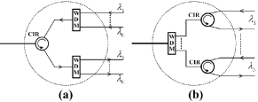
The wavelength-saving topology employs the basic unit consisting of one 3-port circulator (CIR) and two -wavelength WDMs (Fig.1(a)), or one -wavelength WDM and 3-port CIRs (Fig.1(b)). This basic unit can be regarded as a multiplexer joining -wavelength input signals together and a demultiplexer splitting -wavelength output signals apart, denoted as M&D.
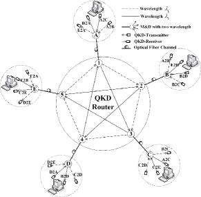
As an example, figure 2 shows the topology of a 5-node RTFC QKD network with 2 wavelengths. Its core component – the 5-port QKD router is composed of five M&Ds. All nodes connect to the router with M&Ds. When node A wants to share secret keys with B, its QKD-Transmitter A2B sends photons of wavelength to its M&D which multiplexes these photons to the optical fiber channel, while arriving at the router, these photons will propagate from port 1 to 2, then forward to node B and be demultiplexed by the M&D, and finally received by B’s corresponding QKD-Receiver A2B. At the same time, if node A want to share other keys with D, who would be required to send photons of wavelength to A. Therefore A can transmit photons of wavelength and to B and C, and receive photons of wavelength and from D and E, respectively and simultaneously. Every node in this architecture is on the same term, so every two nodes can share secure keys directly at the same time only with two wavelengths. Since photons in the network propagate unidirectionally (only from one node to the other), any unidirectional P2P QKD system uni1 ; uni2 ; uni3 ; uni4 ; uni5 ; uni6 can be applied on this QKD network independently. The QKD router can be extended to ports with wavelengths based on the Hamiltonian circuits theorem in odd complete graph theory (Theorem 2-8 in ref.graph ), then the above example can be easily extended to a nodes network.
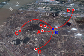
The wavelength-saving 5-node RTFC QKD network with 2 wavelengths (Fig.2) was field tested on the commercial fiber network of China Telecom Corporation Ltd. in Wuhu, Anhui, China. Fig.3 shows locations of 5 nodes and the QKD router in the satellite map, and 25.28km Corning SMF-28e fiber was added behind the commercial fiber at E. The routing rule was as follows: A2B, B2C, C2D,D2E, E2A with , and A2C, C2E, E2B, B2D, D2A with .
Employing BB84bb84 phase coding protocol with 3-intensity decoy state methodma , the asymmetric Faraday-Michelson interferometer (AFMI) setupuni5 was adopted to realize all the P2P QKDs in the network. In each P2P QKD, photon pulses with 750ps duration are generated by a 1530nm (or 1550nm) pulsed laser operating at 20 MHz, and modulated by a fiber-optic intensity modulator (IM) to create signal, decoy and near vacuum sate, then randomly phase-coded () and phase-decoded () by the AFMI pairs belonged to the QKD-transmitter and QKD-receiver respectively, finally detected by single SPD. The InGaAs SPDs produced by Princeton Lightwave have quantum efficiency of about and dark counts of nearly per gate at their maximum trigger frequency 20 MHz and 1ns gate duration. The average photon number of signal state and decoy state are and , and the ratio among the signal state, decoy sate and vacuum state is . Although the extinction ratio of IM is 27 dB, the maximum calculated yield of vacuum states among 10 links is below dark counts of SPDs, so the near vacuum states are vacuum for SPDs.
| A2R2B | A2R2C | D2R2A | E2R2A | |
| Wavelength (nm) | 1530 | 1550 | 1550 | 1530 |
| Attenuation (dB) | 7.24 | 8.78 | 10.79 | 14.77 |
| Crosstalk (dB) | 38.37 | 36.07 | 35.88 | 34.62 |
| Dead-time (s) | 5 | 10 | 25 | 50 |
| Sifted-key (kbit/s) | 31.00 | 17.64 | 8.16 | 3.83 |
| Signal QBER (%) | 2.92 | 2.84 | 2.78 | 3.76 |
| Secure-key (kbit/s) | 4.91 | 2.02 | 1.82 | 0.41 |
Table 1 shows parameters and results for QKD links between A with other four nodes. The attenuation includes the channel attenuation and effective insertion loss 3.10 dB (see posterior paragraph) of network elements. Our control system provide different dead-time for distinct QKD links to achieve optimal secure-key rates. All the P2P QKD systems run over two hours, and more than 115G pulses were sends out from each QKD-Transmitter. For each P2P QKD link, the lower bound of the gain and the upper bound of the error rate of single photon states were estimated according to ref ma , and then the secure key generation rate was achieved by the GLLP formula gllp . Here the statistic fluctuation of measurement wangxb were ignored. With the measurement results in the QKD network, every two nodes could ceaselessly share secure keys after post processing, then these secure keys could be utilized for practical applications.
In order to analyze effects on the P2P QKD system after introducing the wavelength-saving QKD network, an equivalent model is proposed (Fig.4). The left and right M&Ds stand for two nodes respectively, the middle one composed by two M&Ds is an equivalent QKD router. For simplicity, four M&Ds are assumed the same and each one is composed of one CIR and two -wavelength WDMs. In the equivalent model, photons of wavelength from the right node to the left node (Blue in Fig.4) are considered as signal, while photons from other QKD-Transmitters (Red in Fig.4) are traded as crosstalk. Suppose the sifted-key rate and quantum bit error rate (QBER) of the signal are and with the attenuation , the insertion loss and crosstalk are two main performances we will analyze.
Insertion Loss of QKD network elements and channel attenuation compose the attenuation of each QKD link. Compared with P2P QKD systems, four M&Ds are added in the network. However, when we calculate the insertion loss, only three M&Ds need to be considered because the multiplexer part of the M&D following the QKD-Transmitter can be regarded as part of the QKD-Transmitter itself. After introducing the QKD network, the channel attenuation reduced to to get the same , where is the effective insertion loss. We measured the insertion loss by connecting those five M&Ds and the 5-port QKD router with five 12m-long SMF patchcords, the effective insertion loss is dB on average.
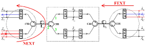
Crosstalk originates from imperfections of network elements and the channel. Since the SPD works in the Geiger mode, we classified crosstalk into point one and continuous one, where the point crosstalk comes from the return loss and directivity of CIRs and back-reflection of joining interfaces between fibers, and the continuous crosstalk is the Rayleigh backscattering in fibers. The interband part, in which the signal and crosstalk have different wavelengths, of point and continuous crosstalk is high order crosstalk in this QKD network, and can be removed by narrow-linewidth lasers and narrow-band filters. Therefore, only the intraband part, in which the signal and crosstalk have the same wavelength, need to be considered. And this part is totally phase-independent of the signal because photons of crosstalk and signal come from two remote lasers. So, the crosstalk considered here is incoherent, and the increased QBER after introducing the QKD network can be expressed as
| (1) |
where is the crosstalk ratio, and . We get the worst crosstalk if all point crosstalk fall in the SPD’s gate duration. However, we can reduce the crosstalk by adding delay in the node’s QKD-transmitter to adjust the arrival time of the point crosstalk, and get the best one if all point crosstalk fall out of the SPD’s gate duration.
The crosstalk in Table 1 was measured as following: every QKD-Transmitter of 5 nodes in Fig.2 was replaced by the corresponding pulse laser, whose average power was adjusted to , when the crosstalk of column A2R2B was measured, we only shut down the 1530nm laser of node A and measured the output power of 1530nm output port belonged to node B, so the crosstalk was (dB), the crosstalk of other columns could be measured in a similar way. Then, the QKD link E2R2A, which has the largest attenuation and crosstalk, was chosen to analyze effects of crosstalk in the field experiment. Considering the worst case, in which all the point crosstalk fall into the gate duration of the SPD, although , the average gain of the crosstalk is still below the dark count of the SPD, and the of the signal state and the decoy state are and respectively, only of either . So, the effects of crosstalk in our field experiment are negligible.
In summary, a wavelength-saving RTFC QKD network has been proposed and field tested at 20 MHz. The experimental results validate that the new topology is feasible for integration into the existing telecom fiber network, and the insertion loss and crosstalk analysis indicates that effects introduced by the QKD network are acceptable.
This work was supported by Wuhu Government and China Telecom Corporation Ltd., Wuhu Branch, and the National Fundamental Research Program of China (Grant No. 2006CB921900), the National Natural Science Foundation of China (Grants No. 60537020 and No. 60621064), the Innovation Funds of Chinese Academy of Sciences, and International Partnership Project.
References
- (1) N. Gisin, G. Ribordy, W. Tittel, and H. Zbinden, Rev. Mod. Phys. 74, 145 (2002).
- (2) P.D. Townsend, S.J.D. Phoenix, K.J. Blow, and S.M. Barnett, Electron Lett. 30, 1875 (1994).
- (3) P.D. Townsend, Nature. 385, 47 (1997).
- (4) C. Elliott, New J. Phys. 4, 46.1 (2002).
- (5) G. Brassard, Proc. SPIE 5260, 149 (2003).
- (6) P.D. Kumavor, J. Lightw. Technol. 24, 3103 (2006).
- (7) T. Zhang, X.F. Mo, Z.F. Han, and G.C. Guo, Phys. Lett. A 372, 3957 (2008).
- (8) W. Chen, et al. IEEE Photonics Tech. Lett. 21, 575 (2009).
- (9) A. Poppe, M. Peev, and O. Maurhart, Int. J. Quantum Inf. 6, 209 (2008).
- (10) T.Y. Chen, et al. Optics Express. 17, 6540 (2009).
- (11) F.X. Xu, et al. Chinese Sci. Bull. 54, 2991 (2009).
- (12) M. Peev, et al. New J. Phys. 11, 075001 (2009).
- (13) C. Marand, and P.D. Townsend, Opt. Lett. 20, 1695 (1995).
- (14) A. Muller, H. Zbinden, and N. Gisin, Europhys. Lett. 33, 335 (1996).
- (15) F. Grosshans, et al. Nature. 421, 238 (2003).
- (16) C. Gobby, Z.L. Yuan, and A.J. Shields, Appl. Phys. Lett. 84, 3762 (2004).
- (17) X.F. Mo, et al. Opt. Lett. 30, 2632 (2005).
- (18) H. Takesue, et al. Nature Photonics 1, 343 (2007).
- (19) N. Deo, Graphy Theory with Apllications to Engineering and Computer Science Ch.2 (Prentice-Hall, Inc., Englewood Cliffs, N.J., 1974).
- (20) C.H. Bennett, and G. Brassard, Proceedings of IEEE International Conference of Computer Systems and Signal Processing, Bangalore, India, 175-179 (IEEE, New York, 1984).
- (21) X.F. Ma, B. Qi, Y. Zhao, and H.K. Lo, Phys. Rev. A 72, 012326 (2005).
- (22) D. Gottesman, H.K. Lo, N. Lütkenhaus, and J. Preskill, Quantum Inf. Comput. 4, 325 (2004).
- (23) X.B. Wang, Phys. Rev. Lett. 94, 230503 (2005).