Photonic spin control for solar wind electric sail
Abstract
The electric solar wind sail (E-sail) is a novel, efficient propellantless propulsion concept which utilises the natural solar wind for spacecraft propulsion with the help of long centrifugally stretched charged tethers. The E-sail requires auxiliary propulsion applied to the tips of the main tethers for creating the initial angular momentum and possibly for modifying the spinrate later during flight to counteract the orbital Coriolis effect and possibly for mission specific reasons. We introduce the possibility of implementing the required auxiliary propulsion by small photonic blades (small radiation pressure solar sails). The blades would be stretched centrifugally. We look into two concepts, one with and one without auxiliary tethers. The use of small photonic sails has the benefit of providing sufficient spin modification capability for any E-sail mission while keeping the technology fully propellantless. We conclude that small photonic sails appear to be a feasible and attractive solution to E-sail spinrate control.
keywords:
electric sail , solar wind , propellantless space propulsionurl]http://www.electric-sailing.fi
1 Introduction
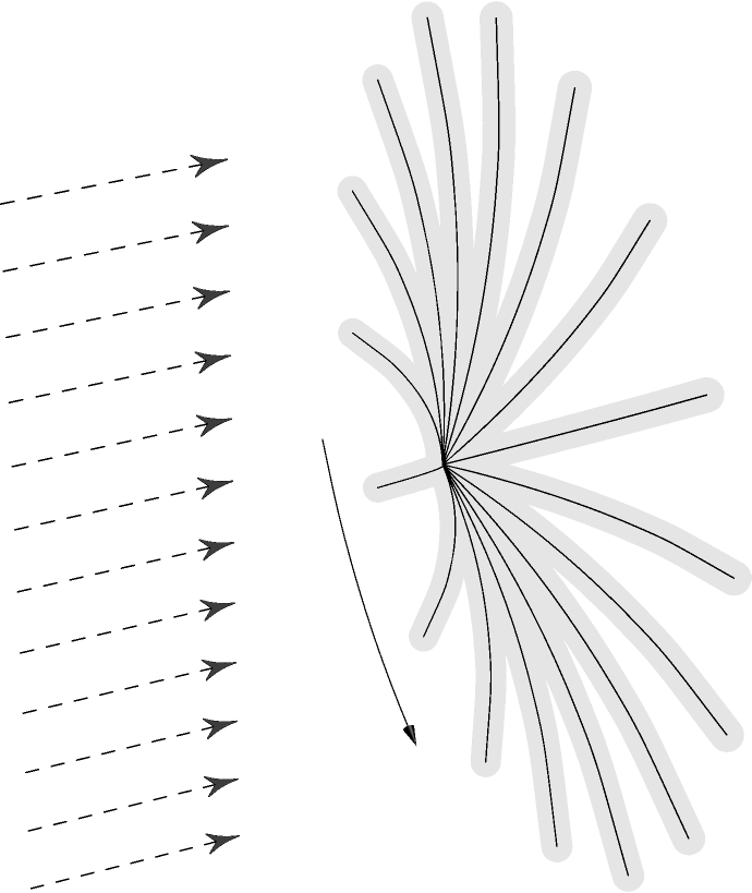
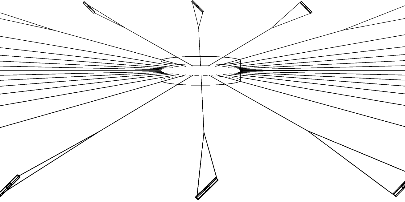
The solar wind electric sail (E-sail) is a newly discovered way of propelling an interplanetary spacecraft by employing the thrust produced by the natural solar wind plasma stream [1, 2]. The solar wind dynamic pressure is tapped by long, thin, centrifugally stretched and positively charged tethers (Figure 1). According to numerical estimations, the E-sail could produce 500 nN/m thrust per unit length [3]. It would seem possible to build e.g. a system with 2000 km total tether length (for example with 80 tethers 25 km long each) whose total mass is kg and which produces 1 N of thrust at 1 AU [4] where AU is the astronomical unit. The thrust scales as where is the solar distance [3]. The predicted performance (1 N thrust at 1 AU, 100-200 kg mass) is high enough that it would enable a large class of previously unattainable missions in the solar system such as sending a 200 kg probe at more than 50 km/s speed out of the solar system to make in situ measurements of interstellar space beyond the heliopause [4].
When compared with the solar photon sail, the solar wind used by the E-sail has 5000 times smaller dynamic pressure than the radiation pressure (2 nPa versus 9 Pa at 1 AU). However, the E-sail has the crucial benefit that it uses a “virtual” sail area made of the static electric field which can be 6 orders magnitude wider (100 m) than the physical width of the tether wires (100 m). Therefore, the efficiency (thrust versus mass) of the electric sail can be at least an order of magnitude better than that of a solar sail using comparable materials. As further benefits, the E-sail can control the thrust vector magnitude and direction independently of each other (the magnitude control is unlimited between zero and some maximum and the direction control capability is 30o).
All E-sail designs require a method of guiding the tethers so that they do not collide with each other despite solar wind variations. Different approaches can be used. One of the methods uses auxiliary tethers which connect the tether tips [4].
For starting and possibly later modifying the spin, small thrusters are needed in the Remote Units that are placed at the tips of the main tethers. In this paper we present and analyse the possibility that these thrusters are implented as small photon sails. We first review the E-sail with auxiliary tethers in general terms, then introduce the photonic thrusters at the tips. After that we look into the possibility of leaving out the auxiliary tethers. The paper ends with a discussion and outlook of the various technical possibilities to implement an electric solar wind sail.
2 E-sail with auxiliary tethers and Remote Units
The E-sail consists of the main spacecraft from which a number of centrifugally stretched main tethers extend outward (Fig. 1). The large tether rig spins slowly so that the centrifugal force keeps the main tethers taut while the solar wind pushes on them. In a full-scale mission there could be 100 tethers each of which is 20 km long.
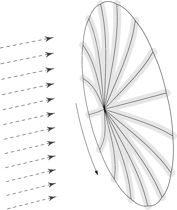
The solar wind varies in time and the E-sail must usually be inclined with respect to the flow to give the desired thrust vector orientation. For this reason the different tethers experience a slightly different solar wind thrust history. This would cause the tethers to eventually spin at slightly different rates, leading them to collide with each other. Any E-sail design must resolve this problem in some way or another. Our baseline approach to solve it is to connect the tips of the main tethers together by non-conducting auxiliary tethers (Fig. 2). The tip of the main tether must then contain a “Remote Unit”, a small autonomous spacecraft which hosts the reel or reels from which the auxiliary tethers are deployed. The Remote Unit must also contain the propulsion system which produces the angular momentum of the tether rig during its initial deployment. The delta-v requirement for the Remote Unit propulsion system is typically few tens of m/s. Two alternative propulsion systems are under investigation and prototyping in the ESAIL FP7 project: a gas thruster and an ionic liquid field effect electric propulsion (FEEP) thruster [5].
Besides producing the initial spin, a need may arise later during propulsive E-sail flight to alter the spinrate. Particularly, if the mission goes around the sun while spiralling inward or outward by keeping the E-sail inclined with respect to the radial solar wind flow, the Coriolis force due to orbital motion results in a net acceleration or deceleration of the E-sail’s spin for outward or inward spiralling orbit, respectively [6]. This secular change of the spinrate is given by
| (1) |
| (2) |
where is the angular frequency due to orbital motion ( where is the orbital period) and is the inclination angle of the sail, taken positive (negative) for orientation causing outward (inward) spiralling orbit. There are some indications that one could to some extent or possibly even fully compensate for the secular spinrate change by modulating the tether voltages in a certain way to utilise the natural small variations in the solar wind direction [6]. Nevertheless, it is prudent to investigate such Remote Unit propulsion systems which allow one to manage the spinrate during flight at will. A cold gas thruster does not have enough delta-v capability for this task, although it is sufficient for producing the initial spin. The ionic liquid FEEP thruster has the potential to accomplish it, however, at least for a substantial class of potential E-sail missions. The Remote Unit propulsion systems are not single failure points because they can back up each other.
3 Remote Units with photonic blades

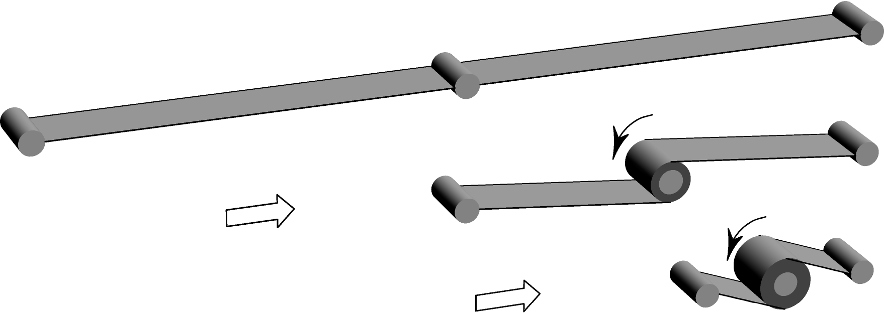
While other solutions exist as explained above, using small photon sails for managing the E-sail spinrate would be an attractive option because photon sails are propellantless (like the E-sail itself) and because at the required performance level they are potentially simple and inexpensive. Figure 3 shows a concept where flexible surface solar blades are deployed between the main tether and the Remote Unit. In the stowed configuration the blade is rolled around a central bar or stick, with additional rigid members keeping it in rectangular shape after deployment (Fig. 4). The blade is stored with the Remote Unit and it is deployed by the centrifugal force when its holding mechanism is released. To obtain spinrate changing torque from the blades they are tilted with respect to sun. The tilting is actuated by the Remote Unit. The Remote Unit will not counterrotate by the blade tilting because the auxiliary tethers keep its attitude constant.
Depending on the size of the main spacecraft and the number of tethers, the blade deployment could occur when some tens of metres of the main tether has been deployed so that the blades can deploy themselves without touching each other. The piece of main tether which is out when blade deployment is performed must be strenthened to withstand the mechanical shock resulting from the blade tightening. For example, it could be made of polyimide tape because that part of the main tether does not necessarily have to be conducting. On the other hand, depending on the radius and moment of inertia of the main spacecraft, the number of tethers and the length of the blades, it might be feasible to perform blade deployment directly from the main spacecraft. In this case the release mechanism of the blades can be the same mechanism which releases the Remote Units from the main spacecraft and no specially strengthened main tether parts are needed.
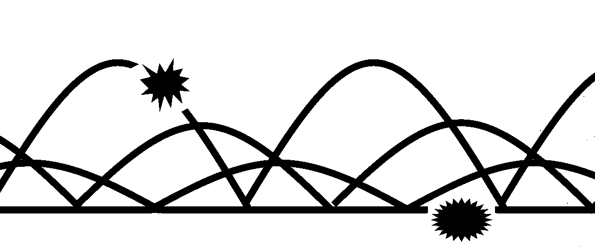
The E-sail main tether which is currently under development is made of a 50 m aluminium base wire onto which three sequences of loop wires of 25 m thickness are bonded ultrasonically at 2-3 cm spacing (Fig. 5 [7]). The loop wires are added to increase the survivability of the tether against micrometeoroid impacts. The base wire is thicker than the loop wires to ease manufacturing. The pull strength of the tether is the same as the breaking strength of the ultrasonic 25 m on 50 m bond which is about 11 cN. With safety margins, a tether tension of 5 cN can be used which corresponds to about 1 cN maximum solar wind force from one tether. According to plasma simulations and theoretical estimates, the expected E-sail force per tether length at 1 AU and at 20 kV tether voltage is 0.5 N/m [3]. The E-sail force scales roughly linearly with the voltage. For fixed tether voltage it scales as the square root of the solar wind dynamic pressure so that its dependence on the solar radial distance is . Notice that the E-sail force decays slower with than the photon pressure which scales as . The reason for the different scaling is that the virtual “sail area” of the E-sail tether is proportional to the solar wind plasma Debye length which scales as where is the solar wind plasma density. The Debye length therefore scales as proportional to which partly cancels the scaling of the solar wind dynamic pressure (the E-sail force per tether length is proportional to the dynamic pressure and the Debye length, the coefficient of proportionality depending on the tether voltage and other parameters).
| Parameter | Symbol | Value |
|---|---|---|
| Number of tethers | 100 | |
| Main tether length | 20 km | |
| E-sail force per length at 1 AU | 500 nN/m | |
| Spin period at 1 AU | 60 min | |
| Diameter of base wire | 50 m | |
| Diameter of loop wire | 25 m | |
| Main tether mass per length | 11.4 g/km | |
| Total mass of main tethers | 22.7 kg | |
| Aux. tether thickness | 7.6 m | |
| Aux. tether tape width | 3 cm | |
| Aux. tether punching | 50% | |
| Aux. tether mass per length | 163 g/km | |
| Total mass of aux.tethers | 20.5 kg | |
| Tether tension at 1 AU | 0.05 cN | |
| Blade thrust required at 1 AU | 5.4 N | |
| Blade area required | 2.7 m2 | |
| Blade mass (7.6 m kapton) | 29 g | |
| Total mass of Remote Units | 50 kg |
Table 1 gives typical parameters for an E-sail having 2000 km total tether length (10020 km) and producing 1 N thrust at 1 AU. The minimum blade area has been calculated from the requirement that it is able to cancel the Coriolis acceleration (1) in circular orbit. We assume 90% reflecting photonic sail material. When the E-sail is inclined to a typical 45o angle with respect to the solar wind flow, the photonic thrust which is available to accelerate or decelerate the spin is about 25% of the full photonic force per area (8.17 N/m2 at 1 AU) that would be obtained by placing the 90% reflecting blade perpendicular with respect to the sun direction; this factor was assumed when computing the required blade area in Table 1. The spin period is adjusted so as to keep the tether tension five times larger than the nominal E-sail force at each distance. According to our dynamical simulations using realistic solar wind data, such tether tension is enough to keep the tether rig stable when auxiliary tethers are used..
If the tether voltage is kept constant, the E-sail thrust scales as where is the solar distance. To keep the ratio of the E-sail force and the centrifugally produced tether tension constant, the sail spin rate must changed as . On a quasi-circular orbit the orbital angular frequency scales as so that the secular angular acceleration of the sail due to the orbital Coriolis effect Eq. (2) scales as . This secular acceleration must be compensated by the photonic blade so that the blade thrust must scale as . Luckily this is the same scaling than that of the solar radiation pressure. Thus we conclude that if the blade is sized to compensate the orbital Coriolis effect at 1 AU, it works at other solar distances as well, at least under the assumption of nearly circular orbits. Although we do not prove it rigorously, it seems likely that the circular orbit represents the worst case for the orbital Coriolis effect so that the blade dimensioning approach described above should be sufficient for any E-sail mission, regardless of the orbit.
Notice in Table 1 that the photonic blade mass (29 g) is an insignificant fraction of the Remote Unit mass (0.5 kg). We assumed 7.6 m kapton for both auxiliary tethers and photonic blades (uncoated in case of auxiliary tethers, doubly aluminised in case of the blades).
The Remote Unit mass estimate of 0.5 kg is derived from ongoing prototyping work in the ESAIL project where the cold gas thruster based Remote Unit’s current dry mass estimate is 0.55 kg. We estimate that the photonic blade version of the Remote Unit would be slightly lighter than the one containing butane tank and two cold gas thrusters, because the mass of the blade itself is not more than 50-100 g (even smaller if advanced thin material is used) and the mass of its tilting mechanism is also not large. From Table 1, the total mass of the tether rig (main tethers, auxiliary tethers and Remote Units with their blades) comes out as 93 kg. Adding to that the mass of the main tether reels, the high voltage subsystem with the electron guns and necessary sensors and control electronics on the main spacecraft would bring the total 1 N E-sail propulsion system mass into the 120-150 kg range. Reducing the total mass to 100 kg seems not to be out of question either. Taking into account that a 1 N E-sail can carry a 1000 kg total mass with reasonably good nominal acceleration of 1 mm/s2. For such applications, reducing the E-sail’s own mass by 30 kg (25%), say, yields only a 9 % increase in the payload capability.
4 Leaving out auxiliary tethers: solar fins
Once the Remote Unit is equipped with a propellantless propulsion device, it should be possible at least in principle to control its rotational state by the E-sail and photonic forces alone, without any help from auxiliary tethers. In other words, in this concept each tether would be equipped with a solar fin and it would be dynamically independent of other tethers (Fig. 6). This requires that the fin angles are continuously adjusted to obtain photonic propulsion not only to compensate the Coriolis effect (1), but also to ensure that the tethers do not collide with each other although solar wind variations and other perturbations introduce small differences in their angular speeds.
In the solar wind concept, the main spacecraft has an imaging system for measuring the instantaneous position of each Remote Unit, while each Remote Unit has a local sun sensor for measuring its angle of rotation about the tether direction. The main spacecraft commands the fin angle of each Remote Unit by radio while the Remote Unit has a local closed loop controller adjusting the ballast mass until the fin’s tilting angle is correct.
The benefits of the solar fin approach include simplicity and mass saving (no auxiliary tethers, reels and motors) and the possibility to scale the system by reducing the number of tethers without necessarily making them shorter (in designs containing auxiliary tethers, such combination of parameters would be uneconomical because it would make the individual auxiliary tethers long and thus increase the size and mass of their storage reels on the Remote Units). Also the possibility to test and demonstrate the dynamical controllability of the tether rig in orbit with a small number of tethers (minimally only one) would be a behefit of the independent tether approach.

Once the Remote Unit does not have auxiliary tethers connected, there is more freedom to select its shape. In particular, we consider that the Remote Unit could be a hollow tube around which the solar fin is initially wrapped (Fig. 7). The solar fin could be made triangular (Fig. 6) instead of rectangular so that no other rigid bars are required. The attitude of the fin could be controlled by actively changing the centre of mass of the Remote Unit. The actuation mechanism could be e.g. a ballast mass that can be moved along the tube by a linear motor. The Remote Unit would be powered by solar panels either mounted on its surface or by thin film solar panels attached on a portion of the photonic fin. For robustness, a battery or other energy storage device would be beneficial to ensure that the unit remains functional in any orientation with respect to the sun. For mass optimisation the energy storage device could be part of the ballast mass and the necessarily electric connections could be made e.g. by thin cylindrical metallic springs connecting the ballast mass to the ends of the tube (Fig. 7). In this way the only sliding contact would be the one associated with the linear motor. In desired, the linear motor could employ magnetic levitation techniques to eliminate sliding contacts completely. The Remote Unit needs to control its orientation actively and continuously by adjusting the ballast mass position. The required control algorithm needs input from local sun sensors as well as transmitted positional information and commands from the main spacecraft.
5 Discussion and outlook
The idea of using small photonic sails for generating the initial E-sail spin and for modifying the spinrate later during E-sail flight (to overcome the orbital Coriolis effect or for mission specific reasons) seems feasible and promising. The required blade size is modest so that the blade can be made lightweight, without the absolute necessity of relying on advanced thin photonic sail materials. The propellantless character of the photonic blades is a benefit which suits well with the propellantless nature of the E-sail itself.
The solution with auxiliary tethers needs one mechanical actuator per Remote Unit for turning the photonic blade. This actuator has to remain functional throughout the E-sail mission. However, failure of a single Remote Unit (either the whole unit or its tilting mechanism) is not mission critical because the only requirement is that the total spinrate control authority provided by the intact Remote Units is sufficient for the mission.
The solar fin solution with no auxiliary tethers incorporates some way of modifying the centre of mass of the bar-like Remote Unit such as a sliding mass moved by a linear motor inside a tubular unit. The latter solution might also be used in a photonic heliogyro sail, as an alternative to the traditional heliogyro layout where the solar fins are rectangular and actuated from the main spacecraft. In a traditional heliogyro the sum of the widths of the photonic fins is limited by the perimeter of the main spacecraft. By placing the solar fins on tips of (longer or shorter) tethers as in Fig. 6, this geometric limitation is relieved. The length of the tubular and stiff Remote Units define the width of the solar fins. This dimension cannot be longer, of course, than the maximum linear dimension available in the launch vehicle, but the bar-like Remote Units can be packed at the main spacecraft in more than one way.
Future engineering and experimental work is needed to study and develop both concepts further. Especially the robustness and reliability of the moving parts in both concepts should be analysed in more detail, and magnetic bearing options should be investigated to see if sliding tribological contacts could be avoided. For the solar fin concept, the question about sufficient fin size to overcome risk of tether collisions due to solar wind variations should be studied by numerical experiments with a dynamical simulator fed by realistic solar wind data.
6 Acknowledgement
The research leading to these results has received funding from the European Community’s Seventh Framework Programme ([FP7/2007-2013]) under grant agreement number 262749. We also acknowledge the Academy of Finland and the Magnus Ehrnrooth Foundation for financial support.
References
- Janhunen [2004] P. Janhunen, Electric sail for spacecraft propulsion, Journal of Propulsion and Power 20 (4) (2004) 763–764.
- Janhunen [2006] P. Janhunen, Electric sail for producing spacecraft propulsion, U.S. Pat. 7641151, Filed March 2 2006 (2010).
- [3] P. Janhunen, Increased electric sail thrust through removal of trapped shielding electrons by orbit chaotisation due to spacecraft body, Annales Geophysicae 27 (2009) 3089–3100.
- Janhunen et al. [2010] P. Janhunen, et al., Electric solar wind sail: towards test missions, Review of Scientific Instruments 81 (2010) 111301.
- [5] S. Marcuccio, N. Giusti, A. Tolstoguzov, Characterization of linear slit FEEP using an ionic liquid propellant, IEPC-09-180, Proc. 31th International Electric Propulsion Conference, Ann Arbor, MI (2009).
- [6] P.K. Toivanen, P. Janhunen, Spin plane control and thrust vectoring of electric solar wind sail by tether potential modulation, Journal of Spacecraft and Rockets, submitted (2012).
- [7] H. Seppänen, S. Kiprich, R. Kurppa, P. Janhunen, E. Haeggström, Wire-to-wire bonding of um-diameter aluminum wires for the Electric Solar Wind Sail, Microelectronic Engineering 88 (2011) 3267–3269.
- Blomqvist [2009] R.S. Blomqvist, Heliogyro control, Ph.D. thesis, Carnegie Mellon University, Pittsburg, Pennsylvania (2009).
- [9] R.H. MacNeal, The heliogyro, an interplanetary flying machine, NASA Contractor’s Report CR 84460 (1967).