Supersonic flutter analysis of thin cracked functionally graded material plates
S Natarajan1,a, M Ganapathi2, S Bordas3
1,aInstitute of Mechanics and Advanced Materials, Theoretical and Computational Mechanics, Cardiff University, U.K. Email: sundararajan.natarajan@gmail.com.
2Head, Stress & DTA, Bombardier Aerospace India Center, IES-Aerospace, Mahindra Satyam Computers Services Ltd., Bangalore, India
3Professor, Institute of Mechanics and Advanced Materials, Theoretical and Computational Mechanics, Cardiff University, U.K.
Abstract
In this paper, the flutter behaviour of simply supported square functionally graded material plates immersed in a supersonic flow is studied. An enriched 4-noded quadrilateral element based on field consistency approach is used for this study and the crack is modelled independent of the underlying mesh. The material properties are assumed to be temperature dependent and graded only in the thickness direction. The effective material properties are estimated using the rule of mixtures. The formulation is based on the first order shear deformation theory and the shear correction factors are evaluated employing the energy equivalence principle. The influence of the crack length, the crack orientation, the flow angle and the gradient index on the aerodynamic pressure and the frequency are numerically studied. The results obtained here reveal that the critical frequency and the critical pressure decreases with increase in crack length and it is minimum when the crack is aligned to the flow angle.
Keywords: Mindlin plate theory, flutter, partition of unity methods, extended finite element method, shear flexible element, functionally graded material.
1 Introduction
The emergence of functionally graded materials (FGMs) that combine the best properties of its constituent materials (for example, ceramics and metals) is considered to be an alternative for certain class of aerospace structures exposed to high temperature environment. FGMs are characterized by a smooth transition from one material to another, thus circumventing high inter-laminar shear stresses and de-lamination problem that persists in laminated composites. The introduction of FGMs has attracted researchers to investigate the structural behaviour of such structures. With the increased use of these materials, it necessitates to study the dynamic characteristics of the structures made up of FGMs.
The investigation of dynamic behaviour of FGM structures is fairly dealt in the literature. Some of the important contributions are discussed here. He et al., (He et al., 2001) presented finite element formulation based on thin plate theory for the vibration control of FGM plate with integrated piezoelectric sensors and actuators under mechanical load, whereas Liew et al., (Liew et al., 1994) have analyzed the active vibration control of plate subjected to a thermal gradient using shear deformation theory. The parametric resonance of FGM plates is dealt by Ng et al., (Ng et al., 2000) based on Hamilton’s principle and the assumed mode technique. Yang and Shen (Yang and Shen, 2001, 2002) have analyzed the dynamic response of thin FGM plates subjected to impulsive loads using Galerkin Procedure coupled with modal superposition methods, whereas, by neglected the heat conduction effect, such plates and panels in thermal environments have been examined based on shear deformation with temperature dependent material properties. The static deformation and vibration of FGM plates based on higher-order shear deformation theory is studied by Qian et al., (Qian et al., 2004) using meshless local Petrov-Galerkin method (MLPG). Matsunaga (Matsunaga, 2008) presented analytical solutions for simply supported rectangular FGM plates based on second-order shear deformation plates, whereas, three dimensional solutions are proposed in (Vel and Batra, 2002, 2004) for vibrations of simply supported rectangular FGM plates. Reddy (Reddy, 2000) presented finite element solutions for the dynamic analysis of a FGM plate and Ferreira et al., (Ferreira et al., 2006) performed dynamic analysis of FGM plate based on higher order shear and normal deformable plate theory using MLPG. Since FGMS are seen as potential candidates for aircraft structural applications, it is important to understand the dynamic characteristics of structures made up of such materials when exposed to air flow. Some of the recent contributions are discussed here. Prakash and Ganapathi (Prakash and Ganapathi, 2006) studied the linear flutter characteristics of FGM panels exposed to supersonic flow. Haddadpour et al., (Haddadpour et al., 2007) and Sohn and Kim (Sohn and Kim, 2008, 2009) investigated the nonlinear aspects of flutter characteristics using the finite element method.
FGM plates or in general plate structures may develop flaws during manufacturing or while in service. The static and dynamic fracture mechanics study of FGMs have been studied in (Dolbow and Gosz, 2002; Nazari et al., 2011). Dolbow and Gosz (Dolbow and Gosz, 2002) employed extended finite element method (XFEM) to compute mixed mode stress intensity factors. Dynamic analysis of FGM beams with edge cracks has been attempted by many researchers (Yang and Chen, 2008; Kitipornchai et al., 2009; Yan and Yang, 2011; Yan et al., 2011). However, such analysis of plates is scarce in the literature (Huang et al., 2011; Natarajan et al., 2011a, b). Huang et al., (Huang et al., 2011) have analyzed the vibration of side-cracked FGM thick plate analytically by employing Ritz procedure, whereas, Natarajan et al., (Natarajan et al., 2011a, b) examined the FGM plate with through center crack using the XFEM. It can be seen from the available literature that the work on flutter characteristics of FGM plates with cracks, to the author’s knowledge is not available in the literature. Earlier studies on flutter characteristics of cracked isotropic and composite panels employed finite element procedure (Chen and Lin, 1985; Pidaparti and Chang, 1998; Shiau, 1992; Strganac and Kim, 1996). Although these numerical studies give insight into understanding the flutter behaviour, the method requires the mesh to conform to the geometry. This inherently limits the analyses to fixed calculation parameters. With the introduction of the extended finite element method (XFEM) (Belytschko and Black, 1999), the requirement of mesh conforming to the geometry is alleviated and it is now possible to model and/or track irregular geometries as they evolve.
In this paper, we apply the XFEM (Belytschko and Black, 1999) to model the crack independent of the underlying mesh and then to study the flutter behaviour of FGM plates immersed in a supersonic flow based on first order shear deformation theory. The crack kinematics is captured by adding suitable functions to the finite element basis. These additional functions are called the ‘enrichment functions’ and the role of such enrichment functions, in this study, is to aid in representing the discontinuity surface independent of the mesh. Here, an enriched four noded shear flexible quadrilateral plate element based on the consistency approach is used to analyse the flutter behaviour. The numerical integration over the elements intersected by the discontinuity surface is done based on conformal mapping (Natarajan et al., 2010), which eliminates the need to sub-triangulate the elements intersected by the discontinuity surface. The influence of the crack length, the crack orientation, the flow direction and the material property on the evaluation of critical speed and the type of fluttering instability is numerically studied.
The paper is organized as follows, the next section will give an introduction to FGM and a brief overview of Reissner-Mindlin plate theory. Section 3 presents results for the flutter analyses of cracked functionally graded material panels, followed by concluding remarks in the last section.
2 Formulation
A rectangular plate made of a mixture of ceramic and metal is considered with the coordinates along the in-plane directions and along the thickness direction (see Figure (1)). The material on the top surface of the plate is ceramic and is graded to metal at the bottom surface of the plate by a power law distribution. The effective Young’s modulus and Poisson’s ratio of the FGM evaluated using the rule of mixtures are:
| (1) |
where is the volume fraction of the phase material. The subscripts and refer to ceramic and metal phases, respectively. The volume fraction of ceramic and metal phases are related by and is expressed as:
| (2) |
where is the volume fraction exponent , also called as the gradient index. The variation of the composition of ceramic and metal is linear for 1, the value of 0 represents a fully ceramic plate and any other value of yields a composite material with a smooth transition from ceramic to metal.
Using Mindlin formulation, the displacements at a point in the plate from the medium surface are expressed as functions of midplane displacements and independent rotations and of the normal in and planes, respectively, as:
| (3) |
The midplane membrane strains , bending strain and shear strain in are written as
| (12) |
where the subscript ‘comma’ represents the partial derivative with respect to the spatial coordinate succeeding it. The strain energy of the plate can be expressed in terms of the field variables and their derivatives as:
| (13) |
where the matrices and are the extensional, bending-extensional coupling, bending and transverse shear stiffness coefficients. The kinetic energy of the plate is given by:
| (14) |
where and is the mass density that varies through the thickness of the plate. The work done by the applied non-conservative loads is:
| (15) |
where is the aerodynamic pressure. The aerodynamic pressure based on first-order, high Mach number approximation to linear potential flow is given by:
| (16) |
where and are the free stream air density, velocity of air, Mach number and flow angle, respectively. The static aerodynamic approximation for Mach numbers between and is (Dixon, 1966; Birman and Librescu, 1990):
| (17) |
The governing equations obtained using the minimization of total potential energy are solved based on the finite element method. The finite element equations thus derived are:
| (18) |
where is the stiffness matrix, is the consistent mass matrix, , is the aerodynamic force matrix and is the natural frequency. When 0, the eigenvalue of is real and positive, since the stiffness matrix and mass matrix are symmetric and positive definite. However, the aerodynamic matrix is unsymmetric and hence complex eigenvalues are expected for 0. As increases monotonically from zero, two of these eigenvalues will approach each other and become complex conjugates. In this study, is considered to be the value of at which the first coalescence occurs.
3 Results and discussion
In this section, we present the critical aerodynamic pressure and the critical frequency of a cracked simply supported FGM panels using the extended Q4 formulation (Natarajan et al., 2011a). The element has five nodal degrees of freedom . The formulation includes transverse shear deformation and in-plane and rotary inertia effects. A full integration scheme is applied to evaluate the various strain energy terms (Somashekar et al., 1987; Ganapathi et al., 1991; Natarajan et al., 2011a). A simply supported boundary condition is assumed for the current study, given by:
| (19) |
In all cases, we present the non dimensionalized critical aerodynamic pressure, and critical frequency as, unless specified otherwise:
| (20) |
where is the bending rigidity of the plate, are the Young’s modulus and Poisson’s ratio of the ceramic material and is the mass density. For this study, the plate thickness is assumed to be 100, unless specified otherwise. In order to be consistent with the existing literature, properties of the ceramic are used for normalization. The effect of material property, the crack orientation , the crack length and the flow angle on the flutter behaviour are studied. Based on progressive mesh refinement, a structured mesh is found to be adequate to model the full plate for the present analysis. The material properties used for the FGM components are listed in Table 1.
Before proceeding with the detailed study, the formulation developed herein is validated against available results pertaining to the critical aerodynamic pressure and critical frequency for an isotropic plate with and without a crack. The computed critical aerodynamic pressure and the critical frequency for an isotropic square plate with various boundary conditions is given in Table 2. Table 3 gives a comparison of the computed frequency and the aerodynamic pressure for a cantilevered square plate with a side crack immersed in a normal flow 0. It can be seen that the numerical results from the present formulation are found to be in good agreement with the existing solutions.
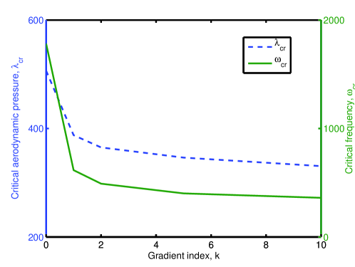
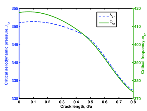
Next, the flutter characteristics of square simply supported cracked FGM plates made of silicon nitride (Si3N4) and steel (SUS304) is investigated. Consider a plate of uniform thickness, and with length and width as and , respectively. Figure (3) shows a plate with all edges simply supported with a center crack of length and a distance of from the axis. In this example, the influence of the crack length , the crack orientation , the flow angle and the gradient index on the critical aerodynamic pressure and the critical frequency is studied. Figure (4) shows the variation of critical aerodynamic pressure and critical frequency with gradient index for a center horizontal crack of length 0.5 in a normal flow 0∘. It can be seen that with increasing gradient index, both the critical aerodynamic pressure and the critical frequency decreases. This is because of the stiffness degradation due to increase in metallic volume fraction. Figure (5) shows the influence of the crack length on the critical aerodynamic pressure and the critical pressure. It is observed that as the crack length increases, the critical aerodynamic pressure and the critical frequency decreases. This is due to the fact that increasing the crack length increases the local flexibility and thus decreases the frequency. It can be seen that the combined effect of increasing the crack length and the gradient index is to lower the critical frequency and the critical pressure. It can also be seen from Figure (4) that the critical pressure and the frequency drops sharply for small increase in the metallic volume fraction, but with further increase in the metallic volume fraction, the drop in the pressure and the frequency is marginal. In both the cases, the decrease in critical aerodynamic pressure and the critical frequency is due to the stiffness degradation.
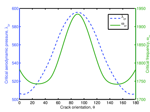
Figure (6) shows the influence of crack angle on the critical pressure and the frequency for a simply supported square FGM plate with gradient index 0, immersed in a normal flow 0∘. From Figure (6) it can be seen that with increase in the crack orientation, the critical pressure increases gradually until the crack is oriented at right angles to the flow angle and with further increase in the crack orientation, the critical pressure and frequency decreases. Further, it is observed that the critical pressure is lowest for a crack orientation 0∘ and 180∘. At these crack orientations, the crack is aligned to the flow direction. The critical frequency and the pressure values tend to be symmetric with respect to a crack orientation 90∘.
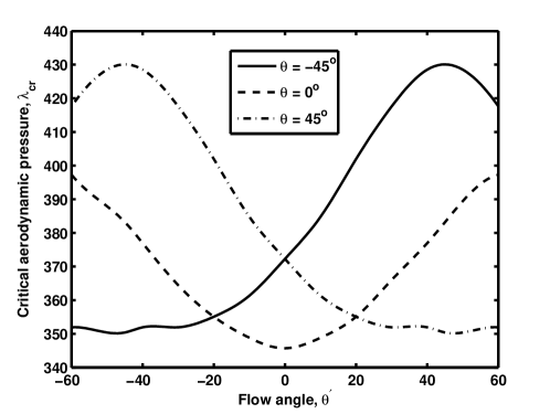
The influence of the flow angle on the critical pressure for a simply supported square FGM plate with gradient index 5 is shown in Figure (7) for different crack orientations, i.e., 0∘, 45∘. It is observed that the critical pressure is minimum when the crack is aligned to the flow angle. The critical frequency increases for other flow angles irrespective of the orientation of the crack.
4 Conclusion
The flutter characteristics of cracked FGM panels immersed in a supersonic flow has been analyzed based on first-order shear deformation theory through the extended finite element approach. The aerodynamic force is accounted for assuming the first-order Mach number approximation potential flow theory and the homogenized material properties are estimated by rule of mixtures. Numerical experiments have been conducted to bring out the effect of the gradient index, the crack length, the crack orientation and the flow angle on the flutter characteristics of the FGM plate. From the numerical study, it can be concluded that with increase in both the gradient index and the crack length, the critical pressure and the frequency decreases. In both cases, the decrease is due to the stiffness degradation. It is also observed that the critical frequency and the pressure is minimum when the crack is aligned to the flow.
References
- Belytschko and Black [1999] T. Belytschko and T. Black. Elastic crack growth in finite elements with minimal remeshing. International Journal for Numerical Methods in Engineering, 45:601–620, 1999.
- Birman and Librescu [1990] V. Birman and L. Librescu. Supersonic flutter of shear deformation laminated flat panel. Journal of Sound and Vibration, 139:265–275, 1990.
- Chen and Lin [1985] W. Chen and H. Lin. Flutter analysis of thin cracked panels using the finite element method. AIAA Journal, 23:795–801, 1985.
- Dixon [1966] S. Dixon. Comparison of panel flutter results from approximate aerodynamic theory with results from exact theory and experiment. Technical Report TN D-3649, NASA, 1966.
- Dolbow and Gosz [2002] J. Dolbow and M. Gosz. On the computation of mixed-mode stress intensity factors in functionally graded materials. International Journal of Solids and Structures, 39:2557–2574, 2002.
- Ferreira et al. [2006] A. J. M. Ferreira, R. C. Batra, C. M. C. Roque, L. K. Qian, and R. M. N. Jorge. Natural frequencies of functionally graded plates by a meshless method. Composite Structures, 75:593–600, 2006.
- Ganapathi et al. [1991] M. Ganapathi, T. Varadan, and B. Sarma. Nonlinear flexural vibrations of laminated orthotropic plates. Computers and Structures, 39:685–688, 1991.
- Haddadpour et al. [2007] H. Haddadpour, H. Navazi, and F. Shadmehri. Nonlinear oscillations of a fluttering functionally graded plate. Composite Structures, 79:242–250, 2007.
- Han and Yang [1983] A. Han and T. Yang. Nonlinear panel flutter using higher-order triangular finite elements. AIAA Journal, 10:1453–1461, 1983.
- He et al. [2001] X. Q. He, T. Y. Ng, S. Sivashanker, and K. M. Liew. Active control of FGM plates with integrated piezoelectric sensors and actuators. International Journal of Solids and Structures, 38:1641–1655, 2001.
- Huang et al. [2011] C. Huang, O. M. III, and M. Chang. Vibrations of cracked rectangular FGM thick plates. Composite Structures, 93:1747–1764, 2011.
- Kitipornchai et al. [2009] S. Kitipornchai, L. Ke, J. Yang, and Y. Xiang. Nonlinear vibration of edge cracked functionally graded timoshenko beams. Journal of Sound and Vibration, 324:962–982, 2009.
- Liew et al. [1994] K. M. Liew, K. C. Hung, and K. M. Lim. A solution method for analysis of cracked plates under vibration. Engineering fracture mechanics, 48(3):393–404, 1994.
- Lin et al. [1991] K. Lin, P. Lu, and J. Tarn. Flutter analysis of anisotropic panels with patched cracks. Journal of Aircraft, 28:899–904, 1991.
- Lin et al. [1989] K.-J. Lin, P.-J. Lu, and J.-Q. Tarn. Flutter analysis of composite panels using high precision finite elements. Computers and Structures, 33:561–574, 1989.
- Matsunaga [2008] H. Matsunaga. Free vibration and stability of functionally graded plates according to a 2-D higher-order deformation theory. Composite Structures, 82:499–512, 2008.
- Natarajan et al. [2010] S. Natarajan, D. R. Mahapatra, and S. P. Bordas. Integrating strong and weak discontinuities without integration subcells and example applications in an xfem/gfem framework. International Journal for Numerical Methods in Engineering, 83:269–294, 2010.
- Natarajan et al. [2011a] S. Natarajan, P. Baiz, S. Bordas, T. Rabczuk, and P. Kerfriden. Natural frequencies of cracked functionally graded material plates by the extended finite element method. Composite Structures, 93:3082–3092, 2011a.
- Natarajan et al. [2011b] S. Natarajan, P. Baiz, M. Ganapathi, and S. Bordas. Linear free flexural vibration of cracked functionally graded plates in thermal environment. Computers and Structures, 89:1535–1546, 2011b.
- Nazari et al. [2011] M. B. Nazari, M. Shariati, M. R. Eslami, and B. Hassani. Computation of stress intensity factor in functionally graded plates under thermal shock. Journal of Mechanical Engineering, 57:622–632, 2011.
- Ng et al. [2000] T. Y. Ng, K. Y. Lam, and K. M. Liew. Effect of FGM materials on parametric response of plate structures. Computer Methods in Applied Mechanics and Engineering, 190:953–962, 2000.
- Pidaparti and Chang [1998] R. Pidaparti and C. Chang. Finite element supersonic flutter analysis of skewed and cracked composite panels. Computers and Structures, 69:265–270, 1998.
- Prakash and Ganapathi [2006] T. Prakash and M. Ganapathi. Supersonic flutter characteristics of functionally graded flat panels including thermal effects. Composite Structures, 72:10–18, 2006.
- Qian et al. [2004] L. C. Qian, R. C. Batra, and L. M. Chen. Static and dynamic deformations of thick functionally graded elastic plates by using higher order shear and normal deformable plate theory and meshless local Petrov Galerkin method. Composites Part B: Engineering, 35:685–697, 2004.
- Reddy and Chin [1998] J. Reddy and C. Chin. Thermomechanical analysis of functionally graded cylinders and plates. Journal of Thermal Stresses, 21:593–629, 1998.
- Reddy [2000] J. N. Reddy. Analysis of functionally graded plates. International Journal for Numerical Methods in Engineering, 47:663–684, 2000.
- Sander et al. [1973] G. Sander, C. Bon, and M. Geradin. Finite element analysis of supersonic panel flutter. International Journal for Numerical Methods in Engineering, 7:379–394, 1973.
- Shiau [1992] L. Shiau. Flutter of composite laminated beam plates with delamination. AIAA Journal, 30:2504–2511, 1992.
- Sohn and Kim [2009] K.-J. Sohn and J. Kim. Nonlinear thermal flutter of functionally graded panels under a supersonic flow. Composite Structures, 88:380–387, 2009.
- Sohn and Kim [2008] K.-J. Sohn and J.-H. Kim. Structural stability of functionally graded panels subjected to aero-thermal loads. Composite Structures, 82:317–325, 2008.
- Somashekar et al. [1987] B. Somashekar, G. Prathap, and C. R. Babu. A field-consistent four-noded laminated anisotropic plate/shell element. Computers and Structures, 25:345–353, 1987.
- Strganac and Kim [1996] T. Strganac and Y. Kim. Aeroelastic behavior of composite plates subjected to damage growth. Journal of Aircraft, 33:68–73, 1996.
- Sundararajan et al. [2005] N. Sundararajan, T. Prakash, and M. Ganapathi. Nonlinear free flexural vibrations of functionally graded rectangular and skew plates under thermal environments. Finite Elements in Analysis and Design, 42(2):152–168, 2005.
- Vel and Batra [2002] S. S. Vel and R. C. Batra. Exact solutions for thermoelastic deformations of functionally graded thick rectangular plates. AIAA J, 40:1421–1433, 2002.
- Vel and Batra [2004] S. S. Vel and R. C. Batra. Three-dimensional exact solution for the vibration of functionally graded rectangular plates. Journal of Sound and Vibration, 272:703–730, 2004.
- Yan and Yang [2011] T. Yan and J. Yang. Forced vibration of edge-cracked functionally graded beams due to a transverse moving load. Procedia Engineering, 14:3293–3300, 2011.
- Yan et al. [2011] T. Yan, S. Kitipornchai, and J. Yang. Parametric instability of functionally graded beams with an open edge crack under axial pulsating excitation. Composite Structures, 93:1801–1808, 2011.
- Yang and Chen [2008] J. Yang and Y. Chen. Free vibration and buckling analyses of functionally graded beams with edge cracks. Composite Structures, 83:48–60, 2008.
- Yang and Shen [2001] J. Yang and H. S. Shen. Dynamic response of initially stressed functionally graded rectangular thin plates. Composite Structures, 54:497–508, 2001.
- Yang and Shen [2002] J. Yang and H. S. Shen. Vibration characteristic and transient response of shear-deformable functionally graded plates in thermal environments. Journal of Sound and Vibration, 255:579–602, 2002.
| Material | Property | |||||
|---|---|---|---|---|---|---|
| Si3N4 | (Pa) | 348.43e9 | 0.0 | -3.070e-4 | 2.160e-7 | -8.946 |
| (1/K) | 5.8723e-6 | 0.0 | 9.095e-4 | 0.0 | 0.0 | |
| SUS304 | (Pa) | 201.04e9 | 0.0 | 3.079e-4 | -6.534e-7 | 0.0 |
| (1/K) | 12.330e-6 | 0.0 | 8.086e-4 | 0.0 | 0.0 |
| Reference | Flutter bounds | Boundary condition | |
|---|---|---|---|
| 1 | 1 | Simply supported | Clamped |
| Ref. [Sander et al., 1973] | 512.2 | 853.40 | |
| 1844.00 | 4292.00 | ||
| Ref. [Han and Yang, 1983] | 512.33 | 852.73 | |
| 1840.55 | 4294.07 | ||
| Ref. [Lin et al., 1989] | 512.58 | 851.50 | |
| 1847.50 | 4290.00 | ||
| Ref. [Prakash and Ganapathi, 2006] | 511.11 | 852.34 | |
| 1840.29 | 4274.32 | ||
| Present | 513.48 | 854.80 | |
| 1849.50 | 4297.00 | ||