Switchable Hyperbolic Metamaterials With Magnetic Control
Abstract
A switchable hyperbolic material (SHM) is investigated, with which one can turn on or off the hyperbolic dispersion of the material via magnetic control. The SHM has simple structure, with a one-dimensional periodic stacking of dielectric layer and gyromagnetic layer. The hyperbolic dispersion of SHM is due to the negative effective permeability of gyromagnetic layers, and it can be transformed into a regular circular dispersion when the d.c. magnetic field is switched off. This switchable dispersion transition is reversible, which may have great potential applications in many fields.
Metamaterials (MMs)PendryPRL2000 ; PendrySmithScience2006 ; LeonhardtScience2006 ; SoukoulisWegenerScience2010 ; ChenShengNM2010 have shown many new striking physics that can be used to control the electromagnetic properties of materials and go beyond the limit that is attainable with naturally existing substances. Unlike photonic crystals, MMs can be viewed as homogeneous media described by effective permittivity and effective magnetic permeability , since their period is much smaller than the working wavelength. For anisotropic MMs, their and/or become tensors. Recently, an important type of the anisotropic MMs, so called “hyperbolic material”, in which one of the diagonal effective permittivity tensor is negative and results in an anomalous hyperbolic dispersion, has attracted growing attentionJacobOE06 ; SalandrinoPRB06 ; YaoScience08 ; LiuScience07 ; ZhangPRL11 ; YangOL10 ; LiAPL08 ; LiuAPL10 . Many interesting phenomena which are difficult to be realized by natural materials, such as hyperlensingJacobOE06 ; SalandrinoPRB06 ; YaoScience08 ; LiuScience07 ; ZhangPRL11 , all-angle nonreflectionLiAPL08 ; YangOL10 , and all-direction pulse compressionLiuAPL10 , etc., can be achieved by these hyperbolic materials.
The realization of a hyperbolic material has recently advanced by adopting the MMs with a periodic metal-dielectric layered structureSalandrinoPRB06 , or periodic metallic linesYaoScience08 . For the performance of the hyperbolic material realized by such structure, one of the most important challenges is the high dissipative losses of MMs, due to the metallic nature of their constituent meta-molecules. To overcome the losses of MMs, one can use gain medium for loss-compensationWuestnerPRL10 . However, this solution need more complex structures, which may bring new challenges in realization. Besides, this loss-compensation is frequency-sensitive, which is a drawback for broadband capacity.
On the other hand, the ability to tune and switch the properties of MMs has greatly broaden the applications of MMs in many fieldsZheludevScience10 , which has been widely studied both experimentally and theoretically in recent years. Very recently, a “big flash” event (a large number of photons emit instantaneously, which has some similarities with the cosmological “big bang”), is predicated to occur during the metric signature transition in hyperbolic materialSmolyaninovPRL10 . The metric signature transition in hyperbolic material is a transition, in which the dispersion relation of the material is changed between hyperbolic and ellipticSmolyaninovPRL10 . Therefore, it is significant to design a switchable hyperbolic material (SHM), with which one can switch on or off the hyperbolic dispersion.
Reviewing the existing efforts, we think the SHM should include at least three characteristics: (I) broadband working frequency; (II) low loss; and (III) switchable hyperbolic dispersion. In this Letter, our design will be presented to serve this purpose.
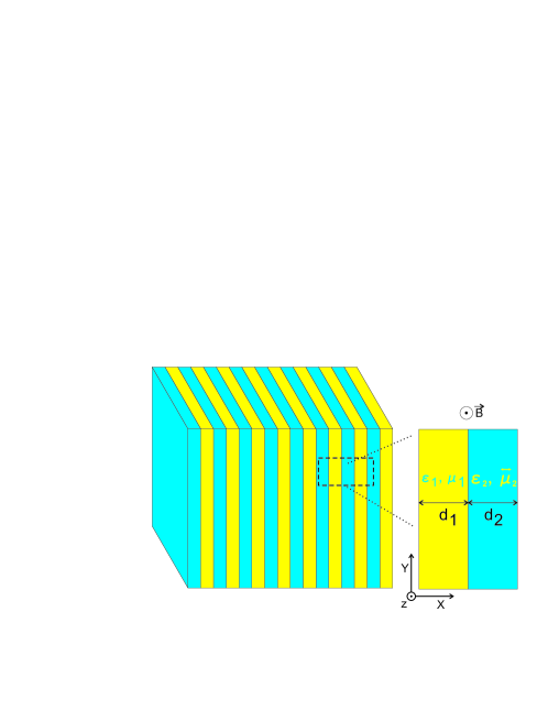
The model of our SHM is schematically shown in Fig.1, in which the SHM is a periodic stacking of dielectric layer and gyromagnetic layer such as yttrium-iron-garnet (YIG) with an external d.c. magnetic field along direction. In our model, the thickness of dielectric layer and gyromagnetic layers are both much smaller than the working wavelengths (about in this work). Therefore, our material can be viewed as the effective anisotropic MMs, which can be described by tensor for TM mode or tensor for TE mode. In this work, only TE mode is consideredZhangSup10 . An obvious difference between our structure and the traditional onesSalandrinoPRB06 ; LiAPL08 is that we use the low-loss gyromagnetic material YIGDasPattonAM2009 ; lossOfYIG instead of the high-loss metallic material.That being said, the dissipative losses of our SHM is naturally very low, which can be neglected in this work because both of the dielectric material and the YIG material in the SHM are nearly lossless. Unlike the traditional hyperbolic material, the dispersion of our SHM is due to the tensor, which can be controlled by the external d.c. magnetic field. Therefore, with magnetic control, one can switch (or tune) the hyperbolic dispersion of the SHM reversibly.
According to real materials, the dielectric constants of dielectric layers and gyromagnetic layers in our model for the SHM are =, and =, respectively. With respect to the relative permeability, the dielectric layers is nonmagnetic with =1, and the gyromagnetic layers has a gyromagnetic formLiuPRB08 :
| (1) |
where , , and describe the direction of the external d.c. magnetic field, respectively. is the resonance frequency with as the gyromagnetic ratio. is the damping coefficient. The characteristic circular frequency is , corresponding to a wave vector . is the speed of light in vacuum. When is 0.16T, the tensor element in YIG WangPRL08 is at 4.28 GHz with and . When , we have and .
Using the transfer-matrix method and imposing the Bloch theorem, the dispersion of our SHM associated with an effective permeability tensor = can be obtained as
| (2) |
where and is the Bloch’s wave vector along axis and the wave vector along axis, respectively, with , , and
| (3) |
Here , , and is the effective permeability of the gyromagnetic layers.
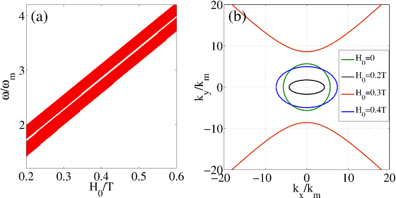
From Eq.(2), one can find that the dispersion of the SHM becomes hyperbolic when . The sign of at different frequency with different external d.c. magnetic field is shown in Fig.2(a), where the white and the red regions indicate positive and negative , corresponding to the elliptic dispersion and the hyperbolic dispersion, respectively. From this figure, we can see the hyperbolic dispersion has two frequency ranges (red regions) for each . The width of each range is about , which is nearly independent on . Between two red regions, there is a very narrow white region with the width of frequency range about for each , corresponding to the elliptic dispersion. Therefore, in the SHM, the total width of frequency ranges that correspond to hyperbolic dispersion is about ( for each , which is quite a considerable broad range for microwave signal processing.
As an typical example, when and , we have and , and the corresponding equifrequency curve is plotted in Fig.2(b) (the red one). Obviously, the dispersion in this case is hyperbolic.
Why the dispersion of our SHM can exhibit hyperbolic with some ? Physically, it can be understood as follows. First, the effective permeability of the gyromagnetic medium , as a function of and , can be negative at some ZhangSup10 ; ZhangJiangAPL2012 . Second, with the negative of gyromagnetic layers in our material, its contribution on the hyperbolic dispersion is similar with that of negative permittivity of metallic layers in the traditional hyperbolic material. As a result, the expression of for the SHM has many similarities with its counterpart for the traditional hyperbolic materialsSalandrinoPRB06 ; LiAPL08 , except the last term in brackets of Eq.(3). This term is due to gyromagnetism, which provides a modification for and it disappears in the nongyromagnetic material.
Our material is tunable. With magnetic control, the dispersion of our SHM can be transformed, due to the change of . As shown in Fig.2(a), for a given frequency, the dispersion of the SHM is able to be changed between hyperbolicity and ellipticity with the control of . To show it more clearly, the dispersion of the SHM at frequency with , , and are calculated, and the corresponding equifrequency curves are respectively plotted in Fig.2(b). In this figure, we can find the dispersion of the SHM can be hyperbolic or elliptic, by changing . When is switched off, i.e., , the dispersion turns into a regular circular one, because our material becomes nonmagnetic in this case.
Our SHM can be used to realize a reversibly tunable metric signature transition by switching on and off. This tunable transition may have a great many potential applications in various fields, i.g., it can be used to control the light on the interface of the SHM. In our previous work, we have demonstrated that the all-angle zero-reflection LiAPL08 and all-direction pulse compressionLiuAPL10 can occur on the interface between the anisotropic medium with hyperbolic dispersion and the isotropic dielectric. Here we would like to show that these striking phenomena can be controlled by with our SHM.
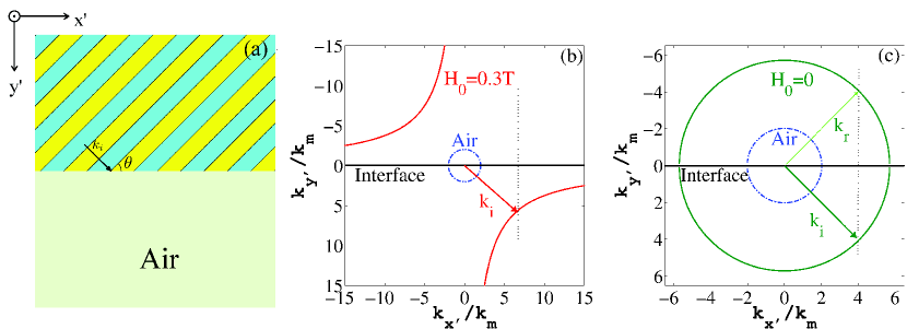
For this, we show the control of electromagnetic wave on the interface between the SHM and air. As shown in Fig.3(a), the surface of the SHM is terminated with a slanted angle , and the electromagnetic wave is incident from the SHM to the air. For the sake of simplicity, we choose a new Cartesian coordinate system - with the same origin, and the angle between and axis is (). After some algebra, the dispersion of the SHM in the new coordinate can be obtained as:
| (4) |
where
| (5) |
with and . The dispersion of our SHM at frequency with , can be obtained from Eq.(4) and the corresponding equifrequency curve are shown in Fig.3(b) and Fig.3(c), respectively. In this work, the slanted angle is chosen as .
For the slanted angle , when a beam from our material with hyperbolic dispersion is incident to the air, there is a critical condition which means the interface ( axis) perpendicular to one of the hyperbola-dispersion asymptotes. When , the critical condition is . At this condition, the beam has zero reflection and zero transmission for all incident angles, which can be seen from the equifrequency curve analysis of reflection and transmission on the interface shown in Fig.3(b). From this figure, we can find that for a incident beam from the SHM to the air with any angle, the transmitted wave is always evanescent wave, so the transmitted energy flux is zero, i.e., zero transmission occurs. Meanwhile, the zero reflection also occurs in this critical condition, for the reflected beam is absent, as shown in Fig.3(b). With this zero-reflection and zero-transmission effect, the incident pulses from the SHM with hyperbolic dispersion can be totally compressed or stopped on the interface.
On the other hand, when is switched off, our material become regular circular dispersion, as shown in Fig.3(c). In this case, the effects of zero reflection, zero transmission, and pulse compression on the interface are also “switched off”. In Fig.3(c), the “zero reflection” becomes “total reflection” with the same incident beam. Therefore, one can control the electromagnetic wave on the interface of our material, just by switching on or off.
In reality, here we emphasis that, control of the electromagnetic wave on the interface of our material is still feasible. Different from the ideal model as discussed above in which the ideal hyperbolic dispersion is still valid when , the strict “zero reflection” and “zero transmission” as well as the completely compressed or stopped pulse on the interface are impossible in reality, since the hyperbolic dispersion described by Eq.(4) is available only when . However, the “near zero reflection”, “near zero transmission”, the strongly compressed and slow pulsesuppl1 could be achieved easily on the interface of our SHM, because in our SHM is a considerable large value comparing with .
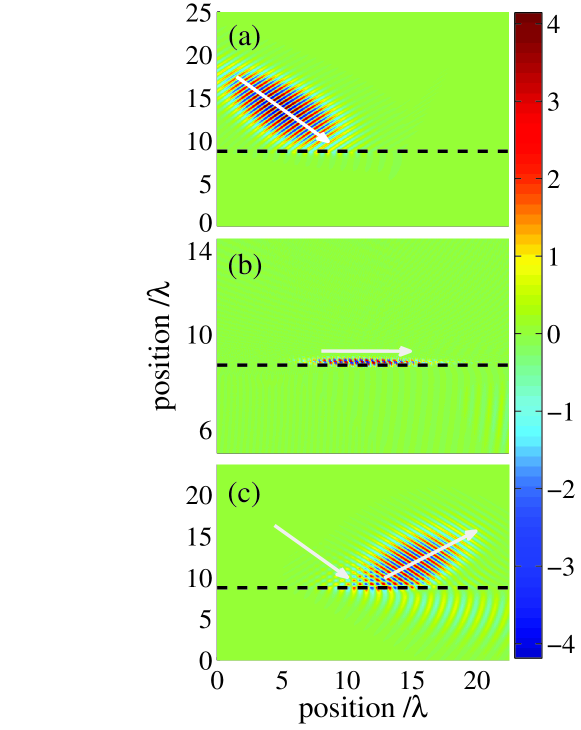
To show more about it, a numerical experiment based on the finite-differential-time-domain (FDTD)eastfdtd method is presented, with the calculated model shown in Fig.3(a). An incident Gaussian pulse at the center frequency from the SHM with is just arriving at the interface, with the field distribution shown in Fig.4(a). When is kept turned on, as shown in Fig.4(b), the pulse is strongly compressed, and the compressed pulse propagates along the interface very slowly. Furthermore, the “near zero reflection” and “near zero transmission” can also be observed in this dynamical process. On the contrast, when is switched off before the pulse arriving at the interface, the pulse is almost reflected, as shown in Fig.4(c). From this figure, we can see that “near total reflection” occurs on the interface, rather than “near zero reflection”, since the dispersion of the SHM in the case of is changed into a circular one with the radium larger than that of air, which can also be seen in Fig.3(c).
Beyond the example presented in this Letter, there can be much more applications of the SHM, for instance, it may be used for the observation on “big flash”SmolyaninovPRL10 , since the SHM is very easy to realize the metric signature transition. The related study of “big flash” in the SHM will be published in our another paper elsewhere.
In conclusion, in this Letter we have presented our design for the SHM, in which one can turn on or off the hyperbolic dispersion via magnetic control. The hyperbolic dispersion of the SHM is due to the negative effective permeability of the gyromagnetic material, and it can be transformed into a regular circular one when the external d.c. magnetic field is switched off. This tunable dispersion transition is reversible, which may have great potential applications in many fields, such as the control of electromagnetic wave on the interface of our SHM. In addition, the SHM may be used to observe “big flash” since the SHM is very easy to realize the metric signature transition.
Acknowledgement. This work was supported by the NSFC (Grant Nos. 11004212, 11174309, and 60938004), and the STCSM (Grant Nos. 11ZR1443800 and 11JC1414500).
References
- (1) J. Pendry, Phys. Rev. Lett. 85, 3966 (2000).
- (2) J. Pendry, D. Schurig, and D. Smith, Science 312, 1780 (2006).
- (3) U. Leonhardt, Science 312, 1777 (2006).
- (4) C. Soukoulis and M. Wegener, Science 330, 1633 (2010).
- (5) H. Chen, C. Chan and P. Sheng, Nat. Mat. 9, 387 (2010).
- (6) Z. Jacob, L. Alekseyev, and E. Narimanov, Opt. Express 14, 8427 (2006).
- (7) J. Yao, Z. Liu, Y. Liu, Y. Wang, C. Sun, G. Bartal, A. M. Stacy, and X. Zhang, Science 321, 930 (2008).
- (8) Z.W. Liu, H. Lee, Y. Xiong, C. Sun, and X. Zhang, Science 315, 1686 (2007).
- (9) S. Zhang, Y. Xiong, G. Bartal, X. Yin, and X. Zhang, Phys. Rev. Lett. 106, 243901, (2011).
- (10) A. Salandrino and N. Engheta, Phys. Rev. B 74, 075103 (2006).
- (11) X. Li, Z. Liang, X. Liu, X. Jiang, and J. Zi, Appl. Phys. Lett. 93, 171111 (2008).
- (12) J. Yang, X. Hu, X. Li, Z. Liu, X. Jiang, and J. Zi, Opt. Lett. 35, 16 (2010).
- (13) Z. Liu, Z. Liang, X. Jiang, X. Hu, X. Li, and J. Zi, Appl. Phys. Lett. 96, 113507 (2010).
- (14) S. Wuestner, A. Pusch, K. Tsakmakidis, J. Hamm, and O. Hess, Phys. Rev. Lett. 105, 127401 (2010).
- (15) N. Zheludev, Science 328, 582 (2010).
- (16) I. Smolyaninov and E. Narimanov, Phys. Rev. Lett. 105, 067402 (2010).
- (17) See supplementary material at [URL will be inserted by AIP] for the dispersion relation and the effective wave vector in an infinite gyromagnetic medium.
- (18) J. Das, Y. Song, N. Mo, P. Krivosik and C. Patton, Adv. Mater. 21, 2045 (2009).
- (19) The imaginary part of the relative permittivity and the relative permeability of a typical YIG material are both as low as in microwave region, which are at least times smaller than that of a metal such as gold.
- (20) S. Liu, J. Du, Z. Lin, R. X. Wu, and S. T. Chui, Phys. Rev. B 78, 155101 (2008).
- (21) Z. Wang, Y. Chong, J. Joannopoulos, and M. Soljačić, Phys. Rev. Lett. 100, 013905 (2008).
- (22) X. Zhang, W. Li and X. Jiang, Appl. Phys. Lett. 100, 041108 (2012).
- (23) The group velocity of the compressed pulse on the interface of our SHM with hyperbolic dispersion is very slow, with the slow limit (perpendicular to the interface) and (parallel to the interface) satisfying: and , where is the slowing coefficient. See also Ref.LiuAPL10 .
- (24) EastFDTD V3.0, DONGJUN Information Technology Co., Ltd., China.