Effect of grain boundary on the buckling of graphene nanoribbons
Abstract
The buckling of graphene nano-ribbons containing a grain boundary are studied using atomistic simulations where free and supported boundary conditions are invoked. We found that when graphene contains a small angle grain boundary the buckling strains are larger when the ribbons with free (supported) boundary condition are subjected to compressive tension parallel (perpendicular) to the grain boundary. The shape of the deformations of the buckled graphene nanoribbons depends on the boundary conditions and the presence of the grain boundary and the direction of applied in-plane compressive tension. Large angle grain boundary results in smaller buckling strains as compared to perfect graphene or to a small angle grain boundary.
Large area graphene sheets have been grown on metallic foils which were found to contain grain boundaries nature2004 . Scanning tunneling microscopy experiments were used to investigate tilt grain boundaries in graphite surfacescience . Transmission electron microscopy was able to observe individual dislocations in graphene science324 . The effect of grain boundaries on both electronic and mechanical properties of graphene was investigated theoretically by Yazyev et al prb81 . Depending on the grain boundary structure, high transparency and perfect reflection of charge carriers over remarkably large energy ranges was reported by using first principle calculations nature2010 . The effects of grain boundaries on the buckling of nano-scale graphene nanoribbons (GNR) has not been investigated up to now, while it is important for their mechanical stability.
Recently, we studied the effect of applied external axial stress on the thermomechanical properties of perfect graphene (PG) prb82neek ; JPCMneek and GNRS containing randomly distributed vacancies APLneek . In this paper we address the effect of the presence of grain boundaries and in-plane boundary compressive stress applied in two different directions, on the buckling and the stability of GNR for the case of supported boundary (SBC) and free boundary conditions (FBC). We found that the presence of grain boundaries: 1) alters the sine wave shape of the longitudinal deformation modes of GNR when subjected to SBC, 2) results in a concave shape of the GNRs when subject to FBC, 3) when subject to compressive tension perpendicular to the grain boundary, the GNR buckles at smaller (larger) strains as compared to perfect graphene in case of FBC (SBC), 4) the buckling transition found for compressive tension parallel to the grain boundary is three times larger than the one for perfect graphene subjected to compressive tension along the zig-zag direction, and 5) free energy calculations reveal that a larger angle grain boundary in suspended graphene when it is subjected to compressive tension makes it unstable.
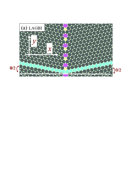
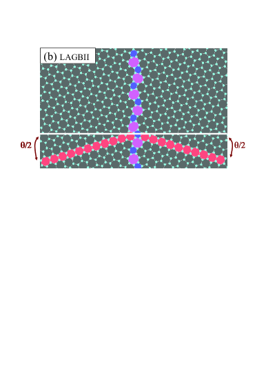
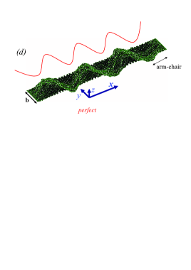
Initially the coordinates of all atoms are put in a flat surface of a honey-comb lattice with nearest neighbor distance equal to . Our perfect GNR (PG) is a rectangular GNR with dimensions nm2 in and directions with armchair (ac) and zigzag (zz) edges, respectively. A grain boundary is introduced as an array of 5-7 defects, which are put in the center of the PG along the y-direction with angle (see Figs. 1). As an example, we study two kinds of grain boundaries which were named LAGBI and LAGBII by Yazyev et al prb81 . These grain boundaries are typical interfaces between domains of graphene with different crystallographic orientation. Mutual orientations of the two crystalline domains is described by the misorientation angle which for LAGBI is 21.8o and for LAGBII is 32.2o. In Figs. 1 we depict two snap shots of the central portion of LAGBI (a) and LAGBII (b) after relaxation at room temperature.
Classical atomistic molecular dynamics simulations (MD) are employed to simulate compressed PG, LAGBI and LAGBII using Brenner’s bond-order potential brenner and temperature is controlled by a Nose’-Hoover thermostat at room temperature. Before starting the compression, the systems are equilibrated during 75 ps (150 000 time steps). Extra atoms were added to the boundaries of the rectangular samples which are characterized by: , . The compression and boundary conditions (FBC and SBC) are applied on these extra atoms which are outside the main systems. Compressing direction is defined by the angle ‘’. For example implies that compression is applied in the -direction (-direction) so that the right (up) longitudinal ends at () are under compressive tension in ()-direction and left longitudinal ends at () are under compressive tension in ()-direction (see Fig. 1 in Ref. prb82neek ). Note that only in PG ‘ac’(‘zz’) direction is equivalent to -direction (-direction). For the lateral ends (for they are and for they are ), we used SBC, (only movement of atoms in lateral ends in the compression direction is allowed not in the direction) and FBC. The FBC (SBC) condition is equivalent to suspended graphene at two longitudinal ends that is put over a trench while it is free at the lateral two ends meyer . Supported boundary condition can be created in experiments by suspending graphene from two longitudinal ends and supporting the other two lateral ends to a substrate which prevents graphene to move verticaly naturenanotechnology .
We applied a strain rate /ns and /ns for and , respectively. The strain rate is given by , where fs is our MD-simulation time step, pm is used as the compression step after each 5000 steps and the factor two is because the compression is applied on two longitudinal ends (for more details see Ref. prb82neek ). Here or if or , respectively. Notice that the atoms in the longitudinal ends are fixed during each compression step.
We use the Jarzynski equality jar , i.e. , which gives a relation between the difference of the free energy and the total work done on the system () during a non-equilibrium evolution where . The averaging is done over several realizations of the paths between the initial and the final state. We found that averaging over 10 simulations with different initial states for each particular case, results in a sufficient accurate value for (more technical details can be found in JPCMneek ; PRLneek ).
Elasticity theory predicts that the shape of the lowest mode of the buckled state (of a simple bar with length , under axial symmetric load applied at its longitudinal ends and free from lateral ends), is half a sine wave, i.e. where is the transverse deflection book ; prb82neek . For a rectangular plate subjected to the SBC, elasticity theory prb82neek ; book predicts the following possible deformations
| (1) |
where are integers in order to satisfy the SBC and is the amplitude of each mode . Including the appropriate strain energy and using Eq. (1), the minimum buckling boundary stress for the considered systems always occurs for and various values of . It is equivalent to a single half wave in the lateral direction and various harmonics in the direction of compression (i.e. perpendicular to the grain boundary).
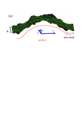
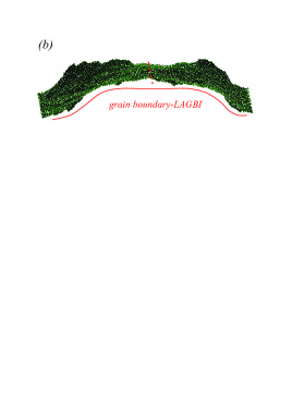
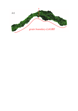
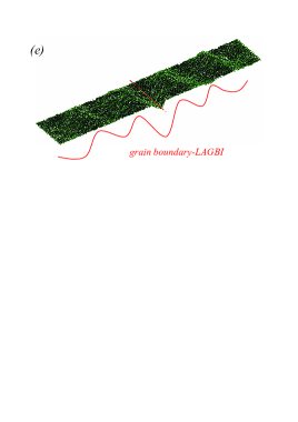
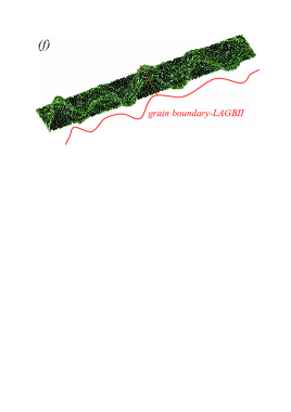
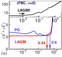
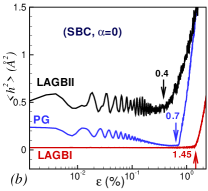
From our simulations we found that after many compression steps GNRs starts to buckle, but the shape of the deformed GNRs was found to depend strongly on the presence of the grain boundary and on the direction of applied compression. Figures 2(a,b,c) (FBC) and Figs. 2(d,e,f) (SBC) show snap shots of the deformed GNRs without (a,d) and with grain boundary (b,c,e,f), beyond the buckling threshold, where and . The strain is calculated using , where () for (). From Figs. 2(a,b,c) we see that the deformed shape for PG is similar to half a sine wave which is much less the case for the LAGBI and LAGBII. The deformations in Figs. 2(d,e,f) satisfy the condition =1 in Eq. (1), while in the direction of the applied compression for LAGBI and LAGBII the shape of the deformation is different from a sine wave which is most clearly seen around the grain boundary.
The buckling threshold, i.e. , is measured by finding the sudden increase in the average quadratic out of plane displacement of the GNR atoms (). The variation of , averaged over ten simulations for , versus are shown in Figs. 3(a,b) for FBC and SBC, respectively. The vertical arrows indicate the transition points to the buckled state. The buckling strains, , are listed in Table 1 for various situations. We found that graphene with LAGBII grain boundary subjected to FBC vibrates quickly so that the relaxed system (before compression) is buckled and thus the buckling strain is zero. This is due to the larger angle misorientation (32.2o). However, notice that before buckling (FBC) for PG fluctuates which is less for LAGBI. Note that a study of the edge reconstruction needs an ab-initio approach which is out of the scope of the present study edge .
Changing varies significantly. In fact for , the buckling strain for LAGBI is three times larger than for PG indicating a considerable change in the structural deformation of graphene when it is subjected to compressive tension along the grain boundary. As seen from Fig. 3(b), for SBC the largest (smallest) buckling strain is for LAGBI (LAGBII) and therefore we conclude that graphene with LAGBII is thermodynamically less stable as compared to LAGBI and PG. This is also confirmed by our free energy calculations. Note that a larger angle grain boundary results in weaker graphene sciencegrain .
| PG | LAGBI | LAGBII | PG | LAGBI | LAGBII | |
|---|---|---|---|---|---|---|
| FBC | FBC | FBC | SBC | SBC | SBC | |
| 0 | 0.6 | 0.34 | 0.01 | 0.7 | 1.45 | 0.4 |
| 1.07 | 3.0 | 0.2 | - | - | - |
The obtained buckling strains are comparable to the one obtained from recent buckling experiments i.e. 0.7 compressionamall ; arxiv2010 . Our theoretical buckling strains are a little smaller than those found in the experiments, which we attribute to the presence of a weak van der Waals interaction between the substrate and graphene in the experiment. Note that strains are more than an order of magnitude smaller than those where fracture occurs in stretching simulations and nanoindentation experiments (they were in the range 10-30) lee .
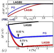
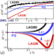
The change in the free energy difference when compressing the GNRs subjected to FBC (SBC) with is shown in the bottom panel of Fig. 3(c) (Fig. 3(d)). Notice that our non-compressed GNRs (in the beginning of the simulations) are flat honeycomb lattice structures (and during the first equilibration we did not change its size) which are not in a thermomechanical equilibrium state at finite temperature. Therefore, the free energy of this state should be higher than the one of the equilibrium state. The free energy of graphene with LAGBII increases with , i.e. there are no minima in the free energy curves either for SBC or for FBC. This is a confirmation of our previous argument about the instability of this system when it is suspended.
Notice that the LAGBI system with FBC (SBC) exhibits a minimum, i.e. equilibrium state corresponds to the minimum points in the free energy curve, for larger strains, 0.73(1.07) as compared to 0.52(0.47) for PG. The reason is that the LAGBI system with a flat surface is much farther from thermodynamical stability than the flat PG. The top panels in Figs. 3(c) and (d) show the first derivative of the free energy for FBC and SBC, respectively. Here the transition is continuous because of the finite size of the simulated GNR.
As seen from the bottom panel of Fig. 3(d) at the minimum point in the free energy curve the rippled state has a lower free energy as compared to the initial non-compressed GNRs; i.e. -10.5 eV, -1.5 eV. Therefore, PG (LAGBI) needs less (more) compression steps to reach its equilibrium size.
In summary, we found that deformations of graphene
nano-ribbons that are subject to in-plane axial boundary
stresses is different when the graphene sheet contains
a grain boundary. In the presence of a grain boundary the GNR subjected to compression
parallel (perpendicular) to the grain boundary has a buckling strain that is largest, i.e. 3 (lowest i.e. 0.34)
when the lateral edges are free. Large angle grain boundaries result in
smaller buckling strain
and into an instability when graphene is suspended.
This work was supported by the Flemish Science Foundation (FWO-Vl) and the Belgian Science Policy (IAP).
References
- (1) A. Hashimoto, K. Suenaga, A. Gloter, K. Urita, and S. Iijima, Nature (London) 430, 870 (2004).
- (2) T. R. Albrecht, H. A. Mizes, J. Nogami, S.-i. Park, and C. F. Quate, Appl. Phys. Lett. 52, 362 (1988).
- (3) X. Li, W. Cai, J. An, S. Kim, J. Nah, D. Yang, R. Piner, A. Velamakanni, I. Jung, E. Tutuc, S. K. Banerjee, L. Colombo, and R. S. Ruoff, Science 324, 1312 (2009).
- (4) O. V. Yazyev and S. G. Louie, Phys. Rev. B 81, 195420 (2010).
- (5) O. V. Yazyev and S. G. Louie, Nature Materials, 9, 806 (2010).
- (6) M. Neek-Amal and F. Peeters, Phys. Rev. B 82, 085432 (2010).
- (7) M. Neek-Amal and F. M. Peeters. J. Phys.: Condens. Matter 23, 045002 (2011).
- (8) M. Neek-Amal and F. M. Peeters, Appl. Phys. Lett. 97, 153118 (2010).
- (9) D. W. Brenner, Phys. Rev. B 42, 9458 (1990).
- (10) J. C. Meyer, A. K. Geim, M. I. Katsnelson, K. S. Novoselov, T. J. Booth, and S. Roth, Nature 446, 60-63 (2007).
- (11) W. Bao, F. Miao, Z. Chen, H. Zhang, W. Jang, C. Dames, and C. Ning Lau, Nature Nanotechnology 4, 562 (2009).
- (12) C. Jarzynski, Phys. Rev. Lett. 78, 2690 (1997).
- (13) M. Neek-Amal, Phys. Rev. Lett. 106, 209701 (2011).
- (14) R. M. Jones, Buckling of Bars, Plates, and Shells, (Bull Ridge, Virginia, 2006) p. 50 and p. 264.
- (15) P. Koskinen, S. Malola, and H. Hakkinen, Phys. Rev. Lett 101, 115502, (2008).
- (16) R. Grantab, V. B. Shenoy, and R. S. Ruoff, Science 330 946 (2010).
- (17) G. Tsoukleri, J. Parthenios, K. Papagelis, R. Jalil, A. C. Ferrari, A. K. Geim, K. S. Novoselov, and C. Galiotis, Small 5, 2397 (2009).
- (18) O. Frank, G. Tsoukleri, J. Parthenios, K. Papagelis, I. Riaz, R. Jalil, K. S. Novoselov, and, C. Galiotis, ACS Nano 4, 3131 (2010).
- (19) C. Lee, X. Wei, J. W. Kysar, and J. Hone, Science 321, 385 (2008).