Proton acceleration by circularly polarized traveling electromagnetic wave
Abstract
The acceleration of charged particles, producing collimated mono-energetic beams, over short distances holds the promise to offer new tools in medicine and diagnostics. Here, we consider a possible mechanism for accelerating protons to high energies by using a phase-modulated circularly polarized electromagnetic wave propagating along a constant magnetic field. It is observed that a plane wave with dimensionless amplitude of 0.1 is capable to accelerate a 1 KeV proton to 386 MeV under optimum conditions. Finally we discuss possible limitations of the acceleration scheme.
I Introduction
Laser induced particle acceleration has drawn considerable interest among researchers all over the world since the pioneering work by Tajima and Dawson tajima . The acceleration gradient of conventional linear accelerators is of the order of V/cm, however today’s state of the art lasers are capable to produce the acceleration gradient many orders of what can be achieved using conventional LINACs. In general laser based accelerators can be divided based on the medium in which the acceleration takes place, which can be either vacuum or a plasma. The vacuum as a medium for particle acceleration has some inherent advantages over plasma medium. The problems like instabilities are absent in vacuum, it is easier to inject the pre-accelerated particle beam in vacuum as compared to the plasma, collisions of particles with media causing energy loss and beam spreading is ruled out, etc. Thus we will focus on particle acceleration in vacuum in this article.
The relativistic motion of the charge particle in large amplitude electromagnetic (EM) fields are studied in detail by many authors. The motion of the charged particle in transverse EM wave and the constant magnetic field along wave propagation is studied by Roberts and Buchsbaum roberts , which was further extended analytically and experimentally by Jorv and Trivelpiece jorv . More recently the in-depth Hamiltonian analysis of the dynamics of charge particle in a circularly polarized traveling EM wave is been studied by Bourdier and Gond gond . Various different schemes have been proposed for the acceleration of charge particle in traveling EM wave feng ; feng2 ; kawata ; singh , some includes the homogeneous magnetic field however some includes the two counter propagating EM waves.
In this paper we will consider an alternative method to accelerate protons in vacuum by circularly polarized electromagnetic waves, where the main new ingredient is a phase-modulation of the EM wave Emphasis would be on understanding the dynamics of proton motion under the proposed scheme. The next section will briefly describe the proposed scheme followed by the results and discussion.
II Model description
A circularly polarized traveling wave propagating along the direction is considered. The electric and magnetic fields of the wave are given by,
| (1) |
| (2) |
and the magnetic fields are expressed as,
| (3) |
| (4) |
with, is the phase modulation function which is given by
| (5) |
where, is the so called phase modulation factor which controls the extent of the modulation. A constant magnetic field is also applied along the direction of wave propagation given by .
The electric fields denoted by Eq. 1 and 2 can be generated by introducing an electro-optic phase modulator. This is an optical device in which a element displaying the electro-optic effect is used to modulate the beam of light. The modulation can be done in phase, frequency, polarization, and amplitude. The simplest kind of modulator consists of a crystal, such as Lithium niobate whose, refractive index is a function of the applied electric field popek . An appropriate electric field along a crystal can be applied in such a way that its refractive index modulates, which eventually will introduce the phase lag in the laser beam. The phase modulation will also depend on the length of the crystal and other parameters. Designing an accurate phase modulator for a specific problem may be an engineering concern, but for the purpose of this article we will assume that such a problem can be solved satisfactorily.
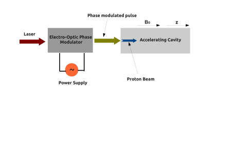
The schematic diagram for the proposed scheme is shown in Fig. 1. The laser pulse is initially passed through the phase modulator so that the spatial and temporal dependence of the electric and magnetic fields are modified according to Eqs. 1, 2, 3 and 4. This modified pulse is then injected into the accelerating cavity, protons under the influence of this modified laser pulse undergoes the acceleration along the transverse direction.
An exact analytical treatment of the problem seems to be too involved because of the nature of electric and magnetic field profiles. It would be a non-trivial task to solve the momentum equations corresponding to the field equations (1)-(4). In view of this we have numerically analyzed the dynamics of the particle under the influence of the given field profiles.
As is wellknown, the motion of the relativistic particle is described by the following equations,
| (6) | |||||
| (7) | |||||
| (8) |
where, , , and are relativistic momentum, velocity, coordinate and mass of the particle. The above equations are solved numerically by a standard Boris leapfrog scheme where particle motion is decomposed into motion in the electric field and the motion in the magnetic field filippychev . The particle orbits is calculated by substituting Eq. (1) -(4) into the equation pf motion, and specifying the initial condition for the injection energy, letting the initial velocity be directed along . In rest of the paper we have used the dimensionless units for all physical quantities.
For all the results presented here, the amplitude of the circularly polarized wave is considered to be (unless otherwise stated), where NOTE . Similarly magnetic field is denoted by . Here, and being the charge and mass of electron, and is the amplitude of electric and magnetic field in SI units with being the laser frequency. The dimensionless space and time are taken in units of the wave number and the angular frequency respectively.
III Numerical Analysis
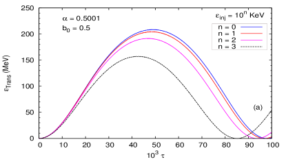
In this article our main focus is to understand the dynamics of a single proton with energy 1 KeV (unless otherwise stated), injected along the propagation direction () of a phase modulated circularly polarized wave with amplitude and a constant magnetic field with magnitude of (Fig. 1) along wave propagation. Although it will be clear later in the article that this scheme is equally valid for the proton beam having some energy spread. The central theme of the proposed scheme is the introduction of the so called phase modulation factor () which can be expressed as the ratio of the phase modulation frequency () to wave frequency i.e. . Next we will see how the value of affects the resulting dynamics of the particle.
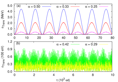
The time evolution of the transverse kinetic energy of the particle for the phase modulation factor with and are presented in Fig. 2 (a). It is observed that the proposed scheme of acceleration works well only when the wave frequency is some harmonics of the modulation frequency. A large deviation from this condition destroy the acceleration mechanism completely, Fig. 2 (b). Furthermore, as can be seen from Fig. 2(a), the efficiency of the scheme deteriorate gradually with higher harmonics of the phase modulation frequency.
It would be interesting to analyze the underlying principle for the success of this acceleration scheme. It turns out that the magnetic field as well as relativistic effects plays only a minor role in this regard. Thus, for the sake of simplicity let us consider the following equation of motion,
| (9) |
where and is the mass and charge of the particle. Only the temporal dependence in Eq. 9 is considered for the purpose of analysis, which is valid assumption since the dynamics is mostly independent of the spatial coordinates. Now using the field profile given by Eq. 1 and phase modulation function given by Eq. 5, this simple equation of motion (Eq. 9)can be integrated to give
| (10) |
where is time in dimensionless units and is a constant of integration. For simplification we have chosen and . The solution of the above integral (Eq. 10) for different values of are shown in Fig. 3. It is quite clear that if , with being an integer the temporal evolution of velocity is very much regular and periodic (Fig. 3 a,c), however for the values when is not an integer the solution of the integral is irregular, (Fig. 3 b,d). The observation is that the success and failure of the proposed acceleration scheme mostly depend on the property of the integral given by Eq. 10. It is observed that acceleration works only when the frequency of the electromagnetic wave is some harmonics of the phase modulation frequency, i.e. with being an integer.

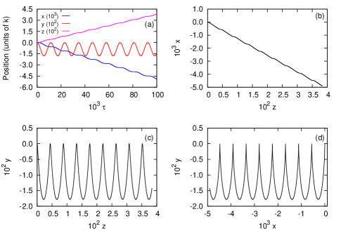
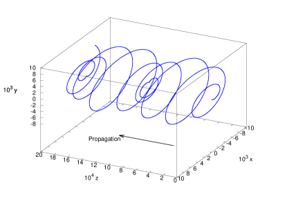
Now let us focus on the trajectories of the particle under the influence of the phase modulated EM wave (Eq. 1, 2, 3 and 4) and external magnetic field (). The time evolution of the particle trajectory along 3 space dimensions is presented in Fig. 4 (a). Here we have considered the value of (the same results holds qualitatively for other valid values of i.e. and ).
The longitudinal displacement along is mainly governed by the energy at which the particle is being injected in the cavity (magenta curve), however oscillatory motion along direction (red curve) is because of the presence of the external magnetic field along direction.
As can be infered from the Fig. 4 (b) and (d), the biggest problem with the acceleration scheme is the excursion along the direction which is much larger than the displacement along the direction of propagation. In this scenario the proposed scheme would be impossible to implement in practice because of the excursion along transverse direction is too large. In order to deal with this problem a small detuning parameter can be added to phase modulation factor , which would be helpful to confine the particle orbits in the x-y plane.
Let us examine the trajectory of the particle after the addition of a small detuning parameter which modifies the phase modulation factor from 0.5000 to 0.5001. It can be observed from Fig. 5(a) that the kinetic energy of particle increased by a factor of about 2 as compared to case when no detuning parameter is present (Fig. 2). Furthermore the trajectory of the particle is modified significantly after the introduction of the detuning parameter. As can be seen, the particle trajectory in the x-y plane (Fig. 5(d)) is closed which make it possible for the acceleration scheme to work in practice.

It should be noted that the selection of the detuning parameter is very crucial for the success or failure of the acceleration mechanism. The value of must be small enough to make the scheme work in favor of acceleration, i. e. we must still have the wave frequency to approximately be a harmonic of the phase modulation frequency, such that the foundation of the scheme is not destroyed, see Fig. 2 (b). Moreover, cannot be too small, as it must be large enough to prevent the large excursions (Fig. 4 b,d).
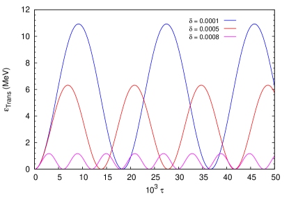
The effect of the detuning parameter on the energetics of the particle is presented in Fig. 6. As can be seen from this figure, reducing the detuning parameter from to increases the efficiency of the acceleration significantly. On the other hand, the transverse kinetic energy of the particle is directly related to the transverse excursion of the particle. For lower values of the the particle orbits are larger such that the electric field of the wave tend to do more work for each orbital motion of the particle. As the detuning increases the particle orbit becomes shorter and shorter, resulting in lower gain in energy from the wave. Apparently there is an optimum detuning at which one is able to gain maximum energy per orbital cycle of the particle.

So far we have presented all the results with constant magnetic field of amplitude . It can be understood that the magnetic field is also responsible along with the detuning parameter to restrict the excursion of particle in transverse direction. In view of this it would be interesting to see how the acceleration efficiency varies with the applied constant magnetic field.
The temporal evolution of the energy varying the constant magnetic field is presented in Fig. 7. The detuned phase modulation parameter in this case is chosen to be 0.5001. It is observed that the proton can now be accelerated to energies of about 386 MeV when the applied magnetic field strength is 0.30. Furthermore, there seems to be an optimum magnetic field for the maximum acceleration of the particle. This behavior can be explained on the basis of the Larmor radius of the particle which varies with the applied magnetic field. The magnetic field should be strong enough to bend the particle to avoid large excursion and should not be so large such that the particle orbit is very small and the resulting energy gain in one orbital motion is small. The particle orbit for the magnetic field is shown in Fig. 8. As can be seen from Fig. 8 the excursion in the transverse direction is controlled. Thus in this case, particle acceleration using a phase modulated electromagnetic wave propagating along a constant magnetic field seems to be possible in a real scenario.
IV Discussion
Here we have focussed on the understanding of the underlying dynamics of the acceleration. We have established that the phase modulated circularly polarized wave can accelerate particles in the presence of a constant magnetic field. There are optimum conditions on the detuning parameter and the magnitude of the magnetic field, in order to gain maximum energies. However, for the purpose of applications, the spectral properties plays a crucial role, in addition to the maximum energy. In view of this it would be important to understand how this scheme works for a particle beam with an energy spread, instead of just a single particle. In order to shed some light on the acceleration dynamics of the particle beam we have separately simulated the single particle motion when injected with different energies, which can be perceived as the energy spectral spread of the beam.
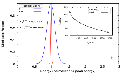
The time evolution of the transverse kinetic energy of single particle is presented in Fig. 9(a) for different injection energies. The phase modulation factor is considered to be and the magnitude 0.5 is considered for the constant magnetic field. It can be observed that even if the injection energies are varied an order of magnitude, the output energy of the beam is not very much affected, keeping the scheme functional. The most important property of the particle beam is its energy distribution function. The energy distribution function of the output beam is calculated in Fig. 9(b) by considering the input beam having Gaussian energy spectrum with peak energy of 600 KeV and FWHM of 166 KeV, the energy spread (/) of the input beam is about 28%. The peak energy of the output beam is observed to be 167 MeV with FWHM of 5 MeV, with the energy spread about 3%.
The inset in Fig. 9(b) shows the variation of output energy with the injected particle energy. Circles denotes the actual numerical value which is fitted with a 10th order polynomial (solid line) in order to find the energy spectrum. The decline in the output particle energy with input energy can be explained on the basis of the interaction time of the particle with the EM wave. The faster the particle, the lesser is the interaction time with the EM wave, and hence the energy transfer to the particle.
As we have observed in Fig. 9(b), the output particle energy is more or less independent of the injected particle energy, which is apparently visible in the almost monoenergetic energy distribution of the output beam.
V Final remarks
A further evaluation of the feasibility of the proposed acceleration scheme need to go beyond the 1D-variations of the electromagnetic fields. In particular, it is clear that picking parameter values corresponding to intense lasers give succesful results for the maximum particle energies. However, a potential limitation is that large transverse particle excursions exclude the use of very focused pulses, in which case the available laser intensity drops accordingly. To some extent this may be remedied with a strong value of the static magnetic field, which limits the transverse excursion. In practice, magnetic field stengths well beyond is needed if the system works in the optical laser regime, which makes this regime less attractive. Decreasing the wave frequency in the scheme reduces the need for extreme magnetic field strengths, since we may allow for somewhat larger particle excursions. The optimal frequency regime may lie in the infra-red regime or lower, but a full 3D analysis is needed to optimize the parameters in a realistic scenario. This remains a project for further research.
Acknowledgements.
This work is supported by the Baltic Foundation, the Swedish Research Council Contract # 2007-4422 and the European Research Council Contract # 204059-QPQV. This work is performed under the Light in Science and Technology Strong Research Environment, Umeå University.References
- (1) T. Tajima and J. M. Dawson, Phys. Rev. Lett., 43, 267 (1979).
- (2) C. S. Roberts and S. J. Buchsbaum, Phys. Rev., 135, A381 (1964).
- (3) H. R. Jorv and A. W. Trivelpiece, J. Appl. Phys., 39, 3053 (1968).
- (4) A. Bourdier and S. Gond, Phys. Rev. E, 62, 4189 (2002).
- (5) L. Feng and Yu-Kun Ho, Phys. Rev. E, 47, R2277 (1993).
- (6) L. Feng and Yu-Kun Ho, Phys. Rev. E, 49, 740 (1994).
- (7) S. Kawata, A. Manabe, H. Watanabe and K. Mizuno, Particle Accelerators, 32, 229 (1990).
- (8) K. P. Singh, Phys. Plasmas, 11, 1164 (2004).
- (9) M. H. Popek,“Electro-optical phase modulator”, US Patent, no. 4886345, (1989).
- (10) D. S. Filippychev, Computational Mathematics and Modeling,12, 193 (2001).
- (11) It should be noted that the is normalized by electron mass, though the dynamics of the proton will be governed by the field amplitude which is about 1836 times less than , resulting in non-relativistic energy regime.