Chargeless heat transport in the fractional quantum Hall regime
Abstract
We demonstrate a direct approach to investigate heat transport in the fractional quantum Hall regime. At filling factor of , we inject power at quantum point contacts and detect the related heating from the activated current through a quantum dot. The experiment reveals a chargeless heat transport from a significant heating that occurs upstream of the power injection point, in the absence of a concomitant electrical current. By tuning in-situ the edge path, we show that the chargeless heat transport does not follow the reverse direction of the electrical current path along the edge. This unexpected heat conduction, whose mechanism remains to be elucidated, may play an important role in the physics of the fractional quantum Hall regime.
pacs:
73.43.Fj, 73.43.Lp, 73.23.HkThe quantum Hall effect arises for two-dimensional electrons subjected to a strong perpendicular magnetic field and involves gapless electronic excitations propagating in channels along the sample edge Wen (1992). It is evidenced from distinct plateaus in the Hall resistance , with the resistance quantum, accompanied by a vanishing longitudinal resistance. At fractional values of the filling factor , this effect is due to Coulomb interaction. It is associated with the formation of exotic electronic phases Laughlin (1983), with quasiparticle excitations markedly different from bosons and fermions and carrying a fraction of the electron charge Saminadayar et al. (1997); de Picciotto et al. (1997). Although the fractional quantum Hall effect was discovered three decades ago Tsui et al. (1982), the experimental investigation of many striking aspects of this physics is still at an incipient stage. This includes the predicted anyonic Wen (1992) and possibly non-abelian statistics Moore and Read (1991) of the fractional quasiparticles, and the presence of correlated electronic edge modes carrying heat but no charge Kane et al. (1994); Lee et al. (2007); Levin et al. (2007).
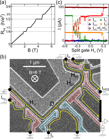
It was pointed out since the mid-nineties that the study of heat transport would provide decisive information on the peculiar physics of the different fractional quantum Hall regimes Kane and Fisher (1997); Levin et al. (2007); Grosfeld and Das (2009); Fertig (2009); Takei et al. (2010); Viola et al. . Very recently, a non-chiral heat transport at several fractional filling factors was evidenced using noise measurements, and attributed to the presence of upstream neutral edge modes Bid et al. (2010); Dolev et al. (2011); Gross et al. (2012). In the present work, we demonstrate a direct approach to investigate heat transport in the fractional quantum Hall regime at the filling factor (Fig. 1(a)). For this purpose we controllably inject power at several locations along the sample channel, using voltage biased quantum point contacts, and detect the resulting heating from the thermally activated current across a quantum dot located at an intermediate edge position (Fig. 1(b)). With this approach, we first evidence an unexpected heating upstream power injection, with respect to the chiral electrical current along the edge. We then demonstrate that this chargeless heat current flows in the bulk, further away from the edge than the electrical path. The relatively important upstream heating suggests the corresponding chargeless heat transport mechanism may play an important role in the physics of the fractional quantum Hall regime.
The studied sample is tailored in a typical two-dimensional electron gas of density and mobility , buried 105 nm deep in a GaAs/Ga(Al)As heterojunction. Note that similar observations on a second sample confirmed the reported findings. We performed the measurements either at DC or by standard lock-in techniques at frequencies below Hz, in a dilution refrigerator of base temperature 40 mK si . Heaters, detector and sample geometry are tuned by field effect using capacitively coupled surface metal gates (Fig. 1(b)). We applied a perpendicular magnetic field T to set the sample in the middle of the zero longitudinal resistance plateau at (see Fig. 1(a) and si , the extracted thermal activation transport gap is mK). According to the effective edge state theory Wen (1992), the electrical edge current at this bulk filling factor is carried by two channels co-propagating in the same direction. The ‘’ outer channel (white line in Fig. 1(b)) is associated to the integer quantum Hall physics, and the ‘’ inner channel to the fractional physics (yellow line in Fig. 1(b)).
The data in Fig. 1(c) confirms the reality of the above edge picture. A bias of pA is applied to the left top contact and the resulting currents are measured at different locations as a function of the split gate voltage tuning the constriction . The current transmitted across is zero for gate voltages below V and increases up to the injected current above . Importantly, shows a wide plateau, larger than , at of the injected current. This plateau corresponds to the full transmission of the ‘’ outer channel, which carries three times more current than the fully reflected fractional ‘’ inner channel. Similar behaviors are observed across all the studied constrictions of this sample. In order to establish the distinctness of the two copropagating channels, the constrictions labeled and were tuned to fully transmitting (reflecting) the outer (inner) channel, and the constriction was closed. In this regime, the vanishing currents and at positive split gate voltages show that the electrical current is carried only by the inner channel, with negligible charge tunneling toward the outer channel between and . Similar tests were performed in presence of the largest injected powers to establish the counter-clockwise (chiral) propagation of the electrical current as well as the absence of inter-channel tunneling in all the experimental configurations investigated hereafter.
Now that we have characterized charge transport, we investigate heat transport by injecting power and probing the resulting heating in the fractional inner edge channel.
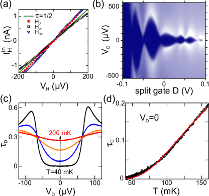
Power is injected locally into the inner channel by applying a voltage bias across a constriction set to transmit half (all) of the current carried by the inner (outer) channel. These constrictions were tuned to have little voltage dependence of their transmission, as shown Fig. 2(a). At half transmission of the inner channel, the injected power into edge excitations is si . One heater is located at an edge distance m upstream the detector , and two heaters and are located respectively at and m downstream the edge channel.
Heating in the fractional inner channel is detected from the activated ac current across the constriction tuned to the Coulomb blockade regime. Interestingly, this regime is here obtained with a simple split gate. Such a behavior is usually attributed to small variations of the 2DEG density of states in the vicinity of the constriction. The Coulomb blockade regime is first evidenced by the appearance of Coulomb diamonds in the bias and gate voltage dependence of the inner channel transmission (Fig. 2(b)). The detector split gate voltage is adjusted using the Coulomb diamonds to tune the activation temperature of to a value much higher than the base temperature, but sufficiently low to detect a small heating. Figure 2(c) displays versus the detector voltage bias and for several temperatures, at the working point used hereafter (unless otherwise specified). In order to minimize power injection at the detector, we probe the electronic temperature from measured at zero detector bias voltage and we restrict our investigation to . The detector is calibrated at thermal equilibrium by measuring versus temperature (Fig. 2(d)). Remarkably, despite the fractional character of the studied ‘’ inner edge channel, we find a very good agreement between the measured (symbols) and the simple Coulomb thermometry expression Beenakker (1991); Kouwenhoven et al. (1997) (red line) with an activation temperature mK, compatible with the non-linear characterization value mK si . In the present heat transport experiment, only one side of the detector is heated up and the electronic energy distribution in the corresponding inner edge channel could be different from an equilibrium distribution function Altimiras et al. (2010a). We therefore extract an effective temperature from the inverted temperature calibration shown Fig. 2(d).
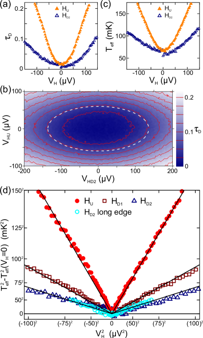
Figure 3(a) shows the detector transmission as a function of the voltage bias applied either to the heater upstream (, ) or downstream (, ), with the inner edge channel fully reflected at . Assuming only that increases with the temperature, we find as expected that heating is the largest for the upstream heater , directly connected to the detector by the current carrying edge modes, and that heating increases with . More surprisingly, the raw data demonstrates the presence of a smaller but relatively important heating from the downstream heater , without associated electrical current. This is in contrast with the co-propagation of heat and charge seen at integer filling factors Granger et al. (2009); Bid et al. (2010), and in particular on the same sample at Altimiras et al. (2010a, b). Figure 3(b) shows on a surface plot of the interplay of heating upstream and downstream the detector (the detector is here set to a slightly higher activation temperature than elsewhere). Remarkably, the equitransmission lines (red) display ellipsoid shapes of similar aspect ratios. This is illustrated at with the ellipse (white dashed line). The detected heating is therefore approximately given by simply summing up the upstream and downstream injected power with a fixed scaling factor. The observation that injecting power in the upstream heater does not facilitate the chargeless heating from confirms that this phenomena is not related to a local destruction of the fractional state.
To investigate further the heat transport mechanisms, and in particular the chargeless heat transport possibly driven by neutral excitations, the effective temperature is extracted from the measured (Fig. 3(c)). In order to focus on the increase in energy density within the ‘’ inner edge channel, we plot for different heater positions as a function of , which is proportional to the injected power (Fig. 3(d)). The validity of this procedure to subtract the thermal background was established experimentally by checking that data taken at different temperatures mK fall on top of each other si . Note that, if we assume a thermal energy distribution at the temperature , the plotted quantity would be directly proportional to the increase in electronic energy density due to the injected power. The increase in the effective energy density is found proportional to the injected power when heating upstream (), as expected in the simple edge channel picture Altimiras et al. (2010a). Interestingly, the same linear dependence is also observed when heating downstream the detection point (, ), in presence of only chargeless heat transport (straight lines are guides to the eye). These observations were reproduced for different settings of the heat detector and on two samples. They are compatible with a proportion of injected power transferred at the heaters into neutral modes, which does not depend on energy (nor on base temperature up to 150 mK si ). It is also consistent with a chargeless heat current that has the same energy dependence as the heat current by the charged edge modes, which is expected to be proportional to the energy density. Interestingly, the same heating is detected when using either the closest downstream heater , or the furthest downstream with an injected power increased by a factor , similar to the heater-detector distance ratio (this quantitative comparison can be done using the raw directly).
Neutral edge modes propagating in the opposite direction to the electrical current are not usually expected at Kane and Fisher (1995). Nonetheless, such phenomena could result from edge reconstruction due to Coulomb interaction in presence of a realistic smooth confinement potential at the edge MacDonald (1990); Aleiner and Glazman (1994); Chamon and Wen (1994); Wan et al. (2002). In order to discriminate between chargeless heat transport along the edge or through the bulk, we deviate the electrical edge path between the detector and the heater toward a macroscopic ohmic contact located six hundred microns away. This is done by opening the intermediate constriction . Note that the same ohmic contact at was found to behave like a reservoir of cold electrons Altimiras et al. (2010b). Here the simultaneous monitoring of the conductance through allows us to ascertain that between and of the electrical current carried by the inner edge channel reaches the contact. Therefore, if the chargeless heat transport is carried by neutral modes following the reverse direction of the electrical current along the edge, we should observe a strong reduction in the detected heating. On the contrary, the corresponding data labeled ‘ long edge’ in Fig. 3(d) ( ) are indistinguishable, at our relative experimental accuracy of si , from injecting power with the same heater without deviating the edge path (). This shows that the presently observed chargeless heat transport propagates through the bulk. We remark that this central conclusion can be reached directly from the raw measurements. Note also that the observation of a similar upstream heat signal, when the injected power and heater-detector distance are scaled by the same factor, is consistent with an isotropic 2D-bulk heat transport (see si for further discussions on heat paths). Intriguingly, the recent noise measurements investigating neutral edge modes Bid et al. (2010); Dolev et al. (2011); Gross et al. (2012) have not pointed out such a chargeless heat transport through the bulk. However, to the best of our knowledge, these previous noise measurements would not discriminate between bulk and edge heat transport si .
The mechanism responsible for the presently observed chargeless heat transport is presently not known. In principle the coupling to phonons is possible, but different estimates suggest it is negligible Martin and Feng (1990); Price (1982); si and it did not result in discernable heat transfers at on the same sample and energy scales for propagation distances up to m le Sueur et al. (2010); Altimiras et al. (2010b); si . Heat transfers between edge states and the electronic excitations in the nearby surface metallic gates were also found negligible at le Sueur et al. (2010); Altimiras et al. (2010b). A possibility is the coupling to low energy spin degrees of freedom in the 2D-bulk. In that respect, it is noteworthy that experimental signatures of a spin-unpolarized 2D-bulk were observed in similar devices set to Clark et al. (1989); Tiemann et al. (2012), and that low energy spin excitations were evidenced from the fragile spin polarization at Plochocka et al. (2009). Another possibility is the coupling to localized electronic states in the 2D-bulk by the long range Coulomb interaction. Such states are more abundant in the fractional quantum Hall regimes, where the fractional gap is not much larger than the energy broadening by disorder. It is conceivable that in our sample, the presence of such states is favored by the wide surface gate located along the edge channel and fixed at ground potential (Fig. 1(b)).
Finally, an important outcome of this work is the demonstration of a direct method to investigate heat transport in the fractional quantum Hall regimes. This opens the path to novel experiments studying the intriguing electronic states found in these regimes.
The authors gratefully acknowledge P. Degiovanni, F. Portier, H. Pothier, P. Roche for discussions. This work was supported by the ERC (ERC-2010-StG-20091028, #259033).
Note added.- Recently, we became aware of two related experimental works investigating heat transport in the quantum Hall regime with quantum dots Venkatachalam et al. ; Gurman et al. .
References
- Wen (1992) X.-G. Wen, Int. J. Mod. Phys B 6, 1711 (1992).
- Laughlin (1983) R. B. Laughlin, Phys. Rev. Lett. 50, 1395 (1983).
- Saminadayar et al. (1997) L. Saminadayar, D. C. Glattli, Y. Jin, and B. Etienne, Phys. Rev. Lett. 79, 2526 (1997).
- de Picciotto et al. (1997) R. de Picciotto, M. Reznikov, M. Heiblum, V. Umansky, G. Bunin, and D. Mahalu, Nature 389, 162 (1997).
- Tsui et al. (1982) D. C. Tsui, H. L. Stormer, and A. C. Gossard, Phys. Rev. Lett. 48, 1559 (1982).
- Moore and Read (1991) G. Moore and N. Read, Nucl. Phys. B 360, 362 (1991).
- Kane et al. (1994) C. L. Kane, M. P. A. Fisher, and J. Polchinski, Phys. Rev. Lett. 72, 4129 (1994).
- Lee et al. (2007) S.-S. Lee, S. Ryu, C. Nayak, and M. P. A. Fisher, Phys. Rev. Lett. 99, 236807 (2007).
- Levin et al. (2007) M. Levin, B. I. Halperin, and B. Rosenow, Phys. Rev. Lett. 99, 236806 (2007).
- Kane and Fisher (1997) C. L. Kane and M. P. A. Fisher, Phys. Rev. B 55, 15832 (1997).
- Grosfeld and Das (2009) E. Grosfeld and S. Das, Phys. Rev. Lett. 102, 106403 (2009).
- Fertig (2009) H. A. Fertig, Physics 2, 15 (2009).
- Takei et al. (2010) S. Takei, M. Milletarì, and B. Rosenow, Phys. Rev. B 82, 041306 (2010).
- (14) G. Viola, S. Das, E. Grosfeld, and A. Stern, “Thermoelectric probe for neutral edge modes in the fractional quantum Hall regime,” ArXiv:1203.3813.
- Bid et al. (2010) A. Bid, O. Nissim, H. Inoue, M. Heiblum, C. L. Kane, V. Umansky, and D. Mahalu, Nature 466, 585 (2010).
- Dolev et al. (2011) M. Dolev, Y. Gross, R. Sabo, I. Gurman, M. Heiblum, V. Umansky, and D. Mahalu, Phys. Rev. Lett. 107, 036805 (2011).
- Gross et al. (2012) Y. Gross, M. Dolev, M. Heiblum, V. Umansky, and D. Mahalu, Phys. Rev. Lett. 108, 226801 (2012).
- (18) See online supplementary material.
- Beenakker (1991) C. W. J. Beenakker, Phys. Rev. B 44, 1646 (1991).
- Kouwenhoven et al. (1997) L. P. Kouwenhoven, C. M. Marcus, P. L. McEuen, S. Tarucha, R. M. Westervelt, and N. S. Wingreen, in Mesoscopic Electron Transport Series E: Applied Sciences, Vol. 345, edited by L. L. Sohn, L. P. Kouwenhoven, and G. Schön (Kluwer Academic, 1997) pp. 105–214.
- Altimiras et al. (2010a) C. Altimiras, H. le Sueur, U. Gennser, A. Cavanna, D. Mailly, and F. Pierre, Nature Phys. 6, 34 (2010a).
- Granger et al. (2009) G. Granger, J. P. Eisenstein, and J. L. Reno, Phys. Rev. Lett. 102, 086803 (2009).
- Altimiras et al. (2010b) C. Altimiras, H. le Sueur, U. Gennser, A. Cavanna, D. Mailly, and F. Pierre, Phys. Rev. Lett. 105, 226804 (2010b).
- Kane and Fisher (1995) C. L. Kane and M. P. A. Fisher, Phys. Rev. B 51, 13449 (1995).
- MacDonald (1990) A. H. MacDonald, Phys. Rev. Lett. 64, 220 (1990).
- Aleiner and Glazman (1994) I. L. Aleiner and L. I. Glazman, Phys. Rev. Lett. 72, 2935 (1994).
- Chamon and Wen (1994) C. d. C. Chamon and X. G. Wen, Phys. Rev. B 49, 8227 (1994).
- Wan et al. (2002) X. Wan, K. Yang, and E. H. Rezayi, Phys. Rev. Lett. 88, 056802 (2002).
- Martin and Feng (1990) T. Martin and S. Feng, Phys. Rev. Lett. 64, 1971 (1990).
- Price (1982) P. J. Price, J. Appl. Phys. 53, 6863 (1982).
- le Sueur et al. (2010) H. le Sueur, C. Altimiras, U. Gennser, A. Cavanna, D. Mailly, and F. Pierre, Phys. Rev. Lett. 105, 056803 (2010).
- Clark et al. (1989) R. G. Clark, S. R. Haynes, A. M. Suckling, J. R. Mallett, P. A. Wright, J. J. Harris, and C. T. Foxon, Phys. Rev. Lett. 62, 1536 (1989).
- Tiemann et al. (2012) L. Tiemann, G. Gamez, N. Kumada, and K. Muraki, Science 335, 828 (2012).
- Plochocka et al. (2009) P. Plochocka, J. M. Schneider, D. K. Maude, M. Potemski, M. Rappaport, V. Umansky, I. Bar-Joseph, J. G. Groshaus, Y. Gallais, and A. Pinczuk, Phys. Rev. Lett. 102, 126806 (2009).
- (35) V. Venkatachalam, S. Hart, L. Pfeiffer, K. West, and A. Yacoby, “Local Thermometry of Neutral Modes on the Quantum Hall Edge,” ArXiv:1202.6681.
- (36) I. Gurman, R. Sabo, M. Heiblum, V. Umansky, and D. Mahalu, “Extracting net current from an upstream neutral mode in the fractional quantum Hall regime,” ArXiv:1205.2945.