Supplementary material to “Jammed frictional tetrahedra are hyperstatic”
1 Particle detection
1.1 Preprocessing
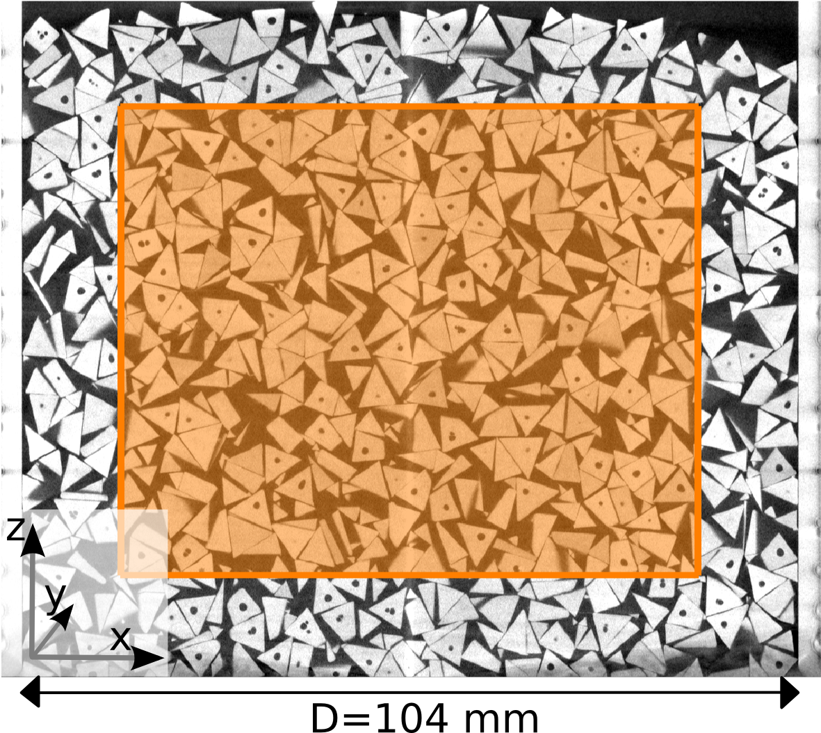
A typical reconstructed volume dataset consists of 1152x1152x1076 voxels with a spatial resolution of per voxel. Figure 1 shows a cut through the central x-z-plane, where the region of interest (ROI) is marked with a rectangle. Note that the particles outside this region are detected as well, but only particles inside the ROI are used in further analysis. The first step is a radially varying binarization using Otsu’s threshold [3], which accounts for the radial brightness decay typically observed in our tomograms.
The second step removes shrinkage cavities, which are inherent to
injection molding, as follows:
-
1.
Inverting the binary image
-
2.
Identifying connected white regions using the MATLAB labeling algorithm bwlabeln [4].
-
3.
Removing regions with voxel volume (hole size threshold)
-
4.
Inverting the image again
1.2 Positions
The approximate centroid positions of the tetrahedra with sidelength are detected by cross-correlation of a sample sphere with the binarized volume. The radius of the sphere is set to the tetrahedra inradius which corresponds to integer voxels. Thresholding the resulting correlation volume with .98 of the maximum value results in a set of center regions, whose centroids are good estimates for the tetrahedra centroids.
1.3 Orientation
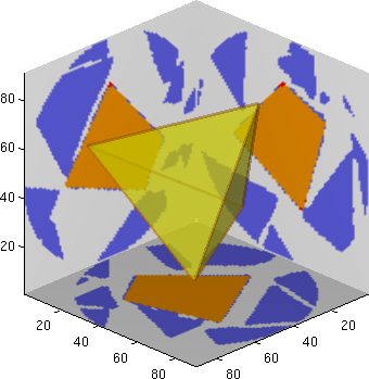
To find the orientation of the individual tetrahedra, we use a binary model tetrahedron which we grow, translate and rotate while maximizing the voxel overlap with the binary tomography data (see Fig. 2). The binary images and are defined as functions which map from to the interval . Note that while is defined in the complete volume, contains only one tetrahedron with a much smaller definition domain .
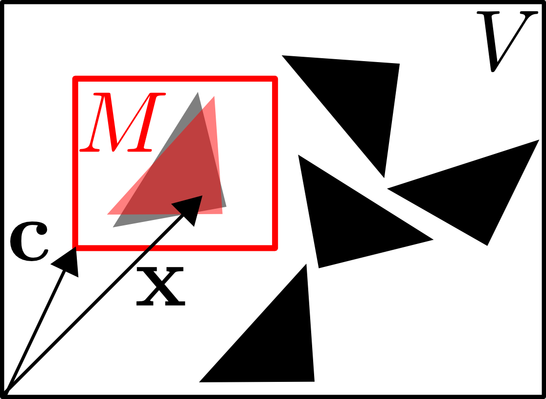
This allows to define the overlap as a spatial convolution[6], usually denoted by . The value of the convolution at a given voxel and given offset is computed by taking the sum of pixels of , weighted by in the subset , where is shifted by the offset :
| (1) |

We implemented a steepest-gradient search algorithm in MATLAB to address the registration problem directly: The model is placed at the approximate centroid position (x,y,z) and set to a random rotation (given as 3 Euler angles , and ). The objective function (“Zielfunktion”) to be maximized is the magnitude of the convolution function as defined in Eq. 1. In each algorithm step, the finite gradient approximation for all 6 parameters is computed, and a move in the gradient direction is performed. The algorithm starts out with a shrunk model (sidelength of and grows the model to the assumed sidelength of , improving robustness and performance. The convergence criterium is the magnitude of the gradient, which is required to be lower than a pre-defined threshold for more than 20 successive steps (as shown in Fig. 3). When this exit condition is reached, and the overlap of model and volume is at least 96% of the theoretical maximum, the particle is marked as detected and removed from the volume.
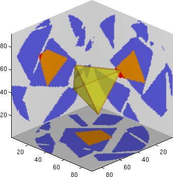
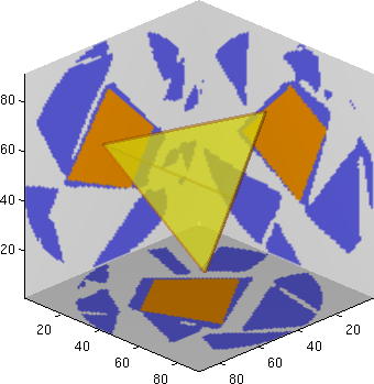
A typical evolution of the parameters during the detection of one tetrahedron is shown in Fig. 3, and Fig. 4. Convergence is reached typically after 40-80 steps, depending on the initial parameters and the local neighborhood.
In some cases, particularly in dense packings with many face-to-face contacts, the particle detection does not converge in the first place. Therefore, the search may be repeated up to 10 times with evenly gridded starting positions and random angles, finally achieving a detection rate in the range of 99.80%-99.95% inside our ROI.
2 Contact analysis
Inter-particle contacts cannot be determined directly from tomographic data because the result is affected by particle polydispersity, imaging artefacts and the finite accuracy of particle detection. However, Aste et al. [1] introduced a method that can provide a physically justified average contact number for spheres of diameter (assuming that experimental errors are distributed gaussian). It defines a number of neighboring particles which includes all particles with a center to center distance smaller or equal to . In the case , can be described by multipying the average contact number with a cumulative normal distribution :
| (2) |
The mean provides an estimate for the bead diameter , and the variance corresponds corresponds to the combined effects of polydispersity and uncertainty of tomography and particle detection.
For there is an additional term to which describes the growing contribution from “spurious” contacts: near neighbors which are close but not in contact. The latter part can be approximated by a linear function with slope combined with the Heaviside step function , leading to the complete model for :
| (3) |
Figure 5 shows an illustration of the model for spheres with a contact number .

We transfer the model to tetrahedra packings as follows: Instead of counting neighbors within a distance , particles are scaled by a “virtual” side length and the number of intersections is counted111A substantial speedup of the analysis is reached by using neighbor cell lists and testing only particles within a diameter of the circumsphere., as shown in Eq. 4:
| (4) |
with the estimated sidelength .
Exemplary contact curves for loose and dense packings are presented in Fig. 6. Firstly, the side length , the contact number , the variance and the linear slope are fitted to the data, using the gnuplot implementation of the non-linear least-squares Levenberg-Marquardt algorithm. Since particles and experimental setup are identical for all 25 samples, we determine the average sidelength and the average variance from all fits ( errors are standard deviations). In a second step, these parameters are fixed, leaving and as the only free parameters.


2.1 Estimation of error bars
The error estimate of the contact number can be calculated by the propagation of error principle: is a function of the estimated sidelength and the distribution width , with the variances and . We denote the errors of the mean values with and . The error of the mean value, , is computed by (with the Student-t-distribution factor according to =20 samples and 95% confidence), respectively for .
The error of is then computed as follows:
| (5) |
where the partial derivates are approximated by the difference quotient approximation
| (6) |
(respectively for ).
3 From contacts to constraints
There are 4 different types of contacts in tetrahedra packings, as table 1 illustrates: face-to-face (F2F) contacts, edge-to-face (E2F) contacts and the point contact configurations vertex-to-face (V2F) and edge-to-edge (E2E). Vertex-Vertex or Vertex-Edge contacts are not observed in practice.
The number of constraints fixed at a specific type of contact is best evaluated by a thought experiment where one of the two particles is kept fixed. In the presence of friction, all contact types will then block three translational degrees of the second tetrahedra: one normal and two tangential. The contact types do however differ in the amount of blocked roational degrees. A frictional face-to-face contacts blocks 3 rotations: one around the surface normal (by friction) and 2 rotations around the two axis standing perpendicular on the surface normal (by non-overlap). An E2F contact blocks only one rotation perpendicular to the surface normal. Finally the pointlike contacts V2F and E2E don’t block any rotation at all. As the constraints are shared between two tetrahedra, we obtain the constraint multipliers , , and . Multiplying these numbers with the according type-specific contact numbers in a specific configuration gives the number of constraints per particle .
| Type | face-to-face | edge-to-face | vertex-to-face | edge-to-edge |
| Example | ![[Uncaptioned image]](/html/1202.6272/assets/f2fexample.png) |
![[Uncaptioned image]](/html/1202.6272/assets/e2fexample.png) |
![[Uncaptioned image]](/html/1202.6272/assets/v2fexample.png) |
![[Uncaptioned image]](/html/1202.6272/assets/e2eexample.png) |
| Constrained | ||||
| DOF | 3 trans. & 3 rot. | 3 trans. & 2 rot. | 3 translational | 3 translational |
| Constraints | ||||
| per Particle | 3.0 | 2.5 | 1.5 | 1.5 |
3.1 Analysis of the contact geometry

In order to determine local contact geometries, all tetrahedra of one sample are scaled to the “contacting” side length , which makes the corresponding consistent (see Fig. 7). Then the pairwise contact geometry of all tetrahedra with their intersecting neighbors is analysed.
Our classification algorithm starts by checking the face-to-face angle , defined as for two contacting tetrahedra q,k, and all face pairs (see also [2, 5]). Visually speaking, this is the angle between normals of adjacent faces, which is 180° for perfect alignment. Because of our finite resolution, we classify a contact as F2F if is higher than a certain threshold value .
3.1.1 Threshold choice for F2F and E2F contacts
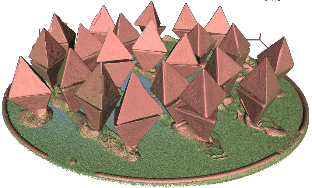
It has been shown[5] that an arbitrary choice of can lead to a physically infeasible constraint number[2], therefore the threshold must be chosen carefully. To this aim, five different samples containing only face-to-face contacts (“F2F sample”) are prepared by glueing one tetrahedron corner-down to a plate and adding another tetrahedron face-down on the top face of the first. A tomographic reconstructions of one of the samples is shown in Fig. 8a and the cumulative distribution of from all samples (containing 90 tetrahedra pairs) is given in Fig. 8b. We find that a cumulative normal function as in Eq.2 with mean ° and variance ° is a good model for the distribution of the face-to-face angle .

We therefore chose the threshold °. This also applies for the classification of an edge-face contact, that is, the angle enclosed between an edge and a face in contact must be smaller than . Vertex-to-face contacts can be identified by analysing if one vertex of tetrahedron is inside the contacting tetrahedron (these intersections are possible due to the scaling to ). Any remaining contacts can then be ascribed to edge-to-edge contacts.
References
- [1] T. Aste, M. Saadatfar, and T. J. Senden. Geometrical structure of disordered sphere packings. Phys. Rev. E, 71:061302, 2005.
- [2] Alexander Jaoshvili, Andria Esakia, Massimo Porrati, and Paul M. Chaikin. Experiments on the random packing of tetrahedral dice. Phys. Rev. Lett., 104:185501, 2010.
- [3] N. Otsu. A threshold selection method from gray-level histograms. IEEE Transactions on Systems, Man, and Cybernetics, 9:62–66, 1979.
- [4] Robert Sedgewick. Algorithms in C, 3rd Ed. Addison-Wesley, 1998.
- [5] Kyle C. Smith, Timothy S. Fisher, and Meheboob Alam. Isostaticity of constraints in amorphous jammed systems of soft frictionless platonic solids. Phys. Rev. E, 84:030301, 2011.
- [6] P. Soille. Morphological Image Processing. Springer, 2004.