Oscillations and translation of a free cylinder in a confined flow
Abstract
An oscillatory instability has been observed experimentally on an horizontal cylinder free to move and rotate between two parallel vertical walls of distance ; its characteristics differ both from vortex shedding driven oscillations and from those of tethered cylinders in the same geometry. The vertical motion of the cylinder, its rotation about its axis and its transverse motion across the gap have been investigated as a function of its diameter , its density , of the mean vertical velocity of the fluid and of its viscosity. For a blockage ratio above and a Reynolds number larger then , oscillations of the rolling angle of the cylinder about its axis and of its transverse coordinate in the gap are observed together with periodic variations of the vertical velocity. Their frequency is the same for the sedimentation of the cylinder in a static fluid () and for a non-zero mean flow (). The Strouhal number associated to the oscillation varies as with : . The corresponding period is then independent of and corresponds to a characteristic viscous diffusion time over a distance , implying a strong influence of the viscosity. These characteristics differ from those of vortex shedding and tethered cylinders for which is instead roughly constant with and higher than here.
I Introduction
The influence of confinement on the motion of a cylinder facing a flow is relevant to many applications like the transport of particles or fibers in slits or the development and localization of bio films inside pores Rusconi2010 ; Autrusson2011 . Many studies have been devoted to this problem but dealt mostly with the determination of the forces on the cylinders (for instance, when they were left free to rotate or eccentered in a stationary flow).
In the studies of the hydrodynamical transport of confined cylinders Dvinsky87a ; Dvinsky87b ; Eklund1994 ; Hu95 , it has usually been assumed that, in the absence of vortex shedding, the motion of the cylinder is steady: the cylinder translates with constant velocity and, in some cases, rotates with a constant angular velocity and at a fixed transverse distance from the mid plane of the gap.
Following these views, non-stationary flows would only appear at Reynolds numbers, , above the vortex shedding threshold. The present work demonstrates instead, at lower Reynolds numbers, a periodic non-stationary transport regime due to another type of flow instability strongly influenced by the viscosity.
Early studies of the torque and drag forces on a cylinder facing a flow have been performed in the Stokes regime or at relatively small Reynolds numbers. For particles placed in the centre of the channel, Faxen Faxen1946 derived the expression of the drag for a confinement less then ; the case of higher confinements has been recently considered by Ben Richou and co workers Richou2004 ; Richou2005 . An eccentered cylinder experiences in addition a positive torque decreasing sharply in the vicinity of the walls Dvinsky87a ; Dvinsky87b ; Hu95 ; Eklund1994 ; for a cylinder translating closely along a wall or held fixed in a Poiseuille flow, this torque tends to generate a rotation of sign opposite to that of contact rolling. This results from the backflow near the second wall and has a sizable influence on the force distribution on the cylinder Champmartin2007 .
The displacement of a free cylinder released from an eccentric position inside a vertical gap has been computed by Hu Hu95 for three values of the Reynolds number . For , the cylinder reaches a final stable transverse position in the middle of the gap. For , instead, an off-axis cylinder rotates in the direction opposite to the previous one, resulting in a lift force oriented away from the axis: this was accounted for by the appearance of a recirculation zone Juarez2000 . However, as the cylinder approaches one of the walls, the recirculation zone recedes because of the interaction between the wake and the wall boundary layer. The rotation and the lift force then change sign again, so that a stable off-axis position is finally found.
Such observations are made at a Reynolds number close to the periodic vortex shedding regime Sahin2004 and are consistent with the conclusions of Zovatto and Pedrizzetti Zovatto2001 for a non rotating cylinder. Above the critical Reynolds number, vortex shedding may induce vibrations of frequency and amplitude depending on the mechanical properties of the system Delangre2010 ; Shiels2001 ; Williamson2008 .
More recently, Semin et al Semin2011 observed that a tethered cylinder placed in a Poiseuille flow between vertical parallel planes oscillates spontaneously at Reynolds numbers below the threshold for vortex shedding: unlike in the present case, both the vertical and rolling motions of the cylinder were blocked.
The present work deals with an horizontal cylinder free to translate and rotate inside the gap of a vertical Hele Shaw cell. Either this cylinder sediments in a stationary fluid or is submitted to a vertical Poiseuille flow (i.e. transverse to its axis): the relative velocity of the cylinder and of the fluid is always below the threshold for vortex shedding. The transverse and vertical components of the motion of the cylinder and its rotation about its axis are studied: the influence of physical parameters such as the diameter and density of the cylinder and the viscosity of the fluid and of hydrodynamical variables like the flow velocity is particularly investigated.
II Description of the experimental setup
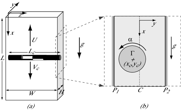
The experimental setup consists of a Hele Shaw cell placed vertically. Its height, width and aperture are respectively , and . The vertical sections of the cell have a Y-shape in their upper part; the upper end of the cell is at the bottom of a rectangular bath with a slit allowing for the flow of the fluid and the insertion of the cylinders. An upward flow may be imposed by a gear pump: the fluid velocity is counted in this case as negative.
| Fluids | () | (mPa.s) |
|---|---|---|
Table 1 lists the characteristics of the fluids used in the experiments; the viscosity is measured using a Contraves Low Shear-30 rheometer. In this study, the natrosol concentration is sufficiently low so that the fluids can be considered as Newtonian: at a given temperature, their viscosity is determined by the natrosol concentration (and increases with it). For shear rates ranging from to , the viscosity (see Tab. 1) of the two natrosol solutions is indeed found to be constant (within ). The density and temperature of the solutions are measured prior to any set of experiments.
The cylinders are made of PMMA (density ) or of carbon (); their diameter ranges from to . Their length is smaller than but as close as possible to the internal width of the cell. Initially, they are placed in the upper bath with their principal axis horizontal and one lets them move down into the Y-shaped zone by reducing the flow rate . Then, may be adjusted so that the cylinder remains at a fixed level either at rest (state ) or oscillates about its principal axis (state ). Then, one may reduce (sometimes to zero) in order to analyze the motion of falling cylinders; in a part of the experiments, is increased again after the cylinder has reached the bottom of the cell for studying its upward motion ().
The displacement of the cylinder is monitored by two cameras triggered synchronously; they image respectively the displacements in the plane of the Hele Shaw cell and in the plane of the gap (the axis is in the midplane between the walls). Processing digitally the two sets of images gives first the instantaneous coordinates of the center of mass of the cylinder in the and planes. The angle between its axis and the horizontal is also determined from the instantaneous location of its two ends in the plane. In order to analyze the rotations of the cylinder around its axis, its length is divided into domains of equal size. The two outside parts are painted in black and two black staggered stripes parallel to the axis are painted on the central portions. The rotation about the axis is analyzed from the variation with time of the local vertical distance between each of the stripes and the principal axis of the rod: this allows one to determine the rotation angle and, therefore, the corresponding angular velocity .
The Reynolds number is defined by:
| (1) |
in which is the width of the gap between the walls and the cylinder (when ), is the mean instantaneous vertical fluid velocity in this gap, and are the fluid density and viscosity. The flow in the gap combines the component imposed by the pump and that induced by the vertical displacement of the cylinder. The velocity is defined as :
| (2) |
in which is the mean velocity far from the cylinder and is the vertical component of its velocity.
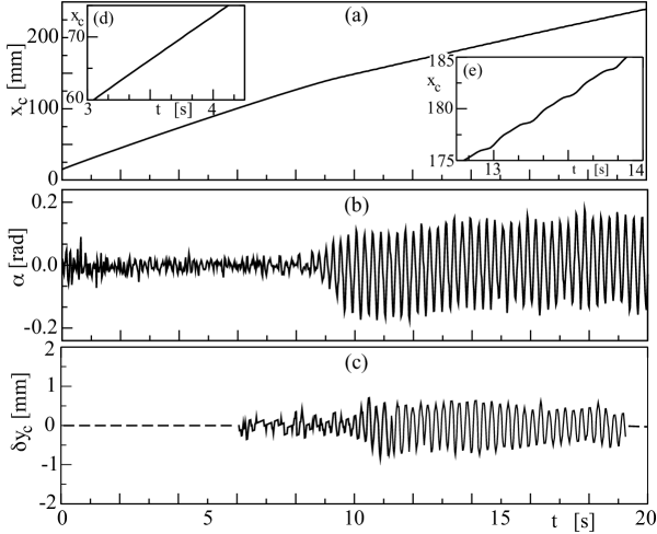
Figure 2 displays experimental results obtained using a PMMA cylinder of diameter and solution . Two distinct regimes are observed:
- at the beginning of this experiment (), the cylinder is located midway between the two vertical walls ( in Fig.2c); it does not roll about its principal axis ( in Fig.2b) and falls at a constant velocity (a linear regression gives ).
- After about the motion of the cylinder suddenly shifts to an oscillating regime: both the angle of the cylinder about its axis and the deviation from the mean transverse position in the gap oscillates with a well defined frequency. At the same time, the vertical translation velocity drops by more than . These two regimes are discussed in detail in sections III and IV below.
III Mean vertical translation velocity for low Reynolds numbers and moderate confinement.
In the present section we are interested in the value of the vertical velocity of the cylinder, averaged over a time larger than the period of the oscillations (if present) but short enough to avoid the influence of global variations. In this section, “velocity” always refers to such an average: for instance in the case of Fig. 2, separate averages are computed before and after the appearance of the oscillations. The vertical velocity is obtained from the equilibrium condition of the gravity and the vertical drag force (averaged over the same time lapse):
| (3) |
here, is the reduced mass per unit length (with ). For a cylinder moving at a constant velocity in a fluid flowing at a constant mean velocity away from the cylinder, the drag may be written in the low Reynolds number limit and when the cylinder does not rotate :
| (4) |
the parameters and reflect the influence of the geometrical confinement. For a long cylinder ( and ), and are only functions of the ratio of the cylinder diameter and of the cell aperture Semin2009 . The vertical velocity of the cylinder is then:
| (5) |
in which
| (6) |
is the velocity of the cylinder with no applied flow ().
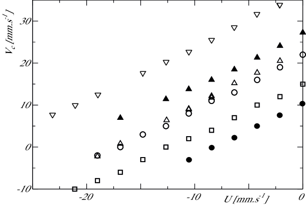
Fig. 3 displays the variation of the velocity of the cylinder with the mean flow velocity in the oscillation and stationary regimes. As predicted by Eq. (5) for viscous flows, increases linearly with in both cases. For a same cylinder diameter () and a same fluid () the velocity in the oscillation regime is lower than in the stationary one at all velocities as suggested above (() and () symbols in Fig. 3); the slope of the variation with is also slightly larger in the oscillation regime.
As also observed by Dvinsky and Popel Dvinsky87a , the sedimentation velocity in a stationary fluid () decreases with the confinement: more generally, at a same velocity , the cylinder velocity is always slightly lower for than for and significantly lower for ((), () and () symbols in Fig. 3). This would have been the opposite for cylinders falling in a tank of size much larger than their diameter (): in this unconfined case, the sedimentation rate increases with because the mass per unit of length varies faster (as ) than the drag force.
In the confined case, instead, Ben Richou et al. Richou2005 found numerically in the lubrication approximation that the geometrical factor increases like for . Combining the variations of and in Eq. 6, the velocity must then decrease with (or equivalently with ) as is indeed observed.
Finally, the experiments confirm that increasing the fluid viscosity for a given cylinder reduces the value of and result in a transition from an oscillation to a stationary regime (() and () symbols in Fig. 3). For a significantly larger cylinder density, increases strongly, even for more viscous fluids (() symbols in Fig. 3).
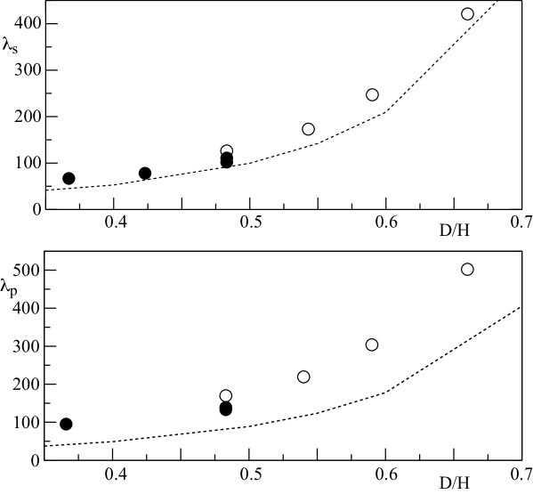
In these experiments, the factor is deduced by means of Eq. 6 from the experimental data for : the corresponding values are plotted in Fig. 4.
In both the stationary and oscillation regimes, the experimental variation of with is similar to that predicted by Ben Richou et al. Richou2004 ; Richou2005 (also plotted on the figure). The difference between the experimental and predicted values is at most : it is likely due to inertial effects, in agreement with the variations of the drag with the Reynolds number reported by Hu Hu95 and Ben Richou Richou2005 . Note that the influence of the space between the ends of the rod and the lateral sides of the cell cannot account for this difference : the corresponding bypass flow would indeed instead reduce the measured value of (see Fig. in Ref. Semin2009, ).
For , the transition from the stationary to the oscillation regime leads to a small increase () of . This variation reflects the complex interplay between the rolling motion of the cylinder and its displacement across the gap during the oscillations. The values in the two regimes are however remarkably similar.
IV Oscillation regime
IV.1 Time variation of the transverse displacement in the gap
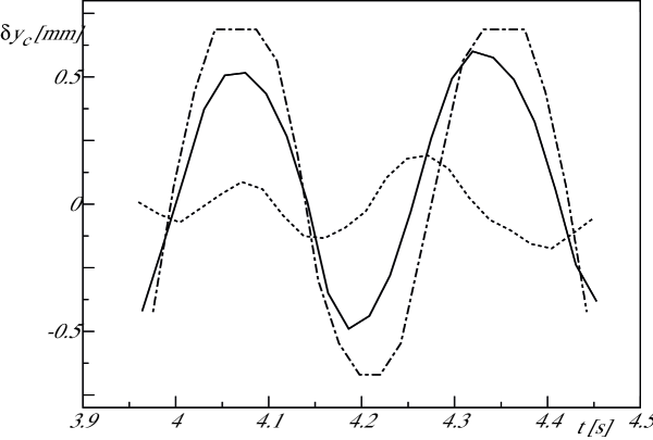
Examples of variations with time of the transverse displacement of the cylinder from its mean position in the gap are displayed in Fig. 5 for different flow velocities . The amplitude of the oscillations close to the threshold () is small () but it increases rapidly with and reaches a saturation value of the order of for . This maximum is close to the clearance between the cylinders and the cell walls (): it corresponds then to cylinders coming very close to the walls during their motion as shown by the curve corresponding to . Fig.5 also shows that the period of the oscillation is equal within for and and only lower for . This variation with the velocity is qualitatively much slower than for vortex shedding and tethered cylinders (see Semin2011, and references therein.
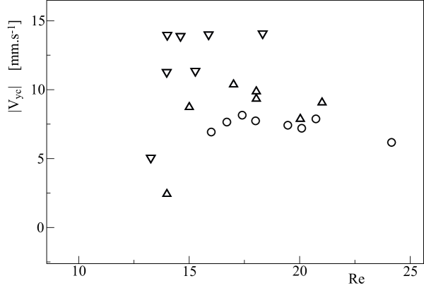
The transverse velocity reaches a maximum for . The values of measured for different cylinders in both solutions and are plotted in Fig. 6 as a function of the Reynolds number . After a sharp increase over a narrow range of values (), reaches a constant limit. This upper value decreases as the diameter of the cylinder increases (() and () symbols in Fig. 6); it depends also on the cylinder density and on the fluid viscosity (() and () symbols).
IV.2 Time variation of the roll angle .
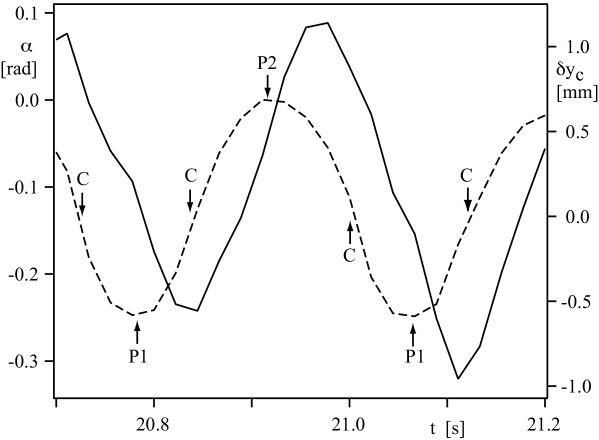
The variations with time of the both the roll angle and the transverse displacement are plotted in Fig. 7. Both parameters vary periodically with the same frequency but the shape of the variation of is more triangular. This reflects very fast changes of the direction of the rotation which last for less than : they take place shortly after the distance between the cylinder and the cell walls has reached its minimal value ().
As the cylinder moves towards one of the walls, it rotates always in the direction opposite to the local vorticity corresponding to the mean flow (see Fig.1); the rotation changes direction while it moves away so that it is again opposite to the local vorticity when it reaches the other wall. The corresponding absolute tangential velocity of the surface of the cylinder at that time is close to and is of the order of the absolute flow velocity . Note that the velocity of the cylinder surface facing the nearest wall has always the same sign: both the rotation direction and the side of the cylinder involved change indeed from one half period to the next.
IV.3 Variation of the vertical velocity of the particle
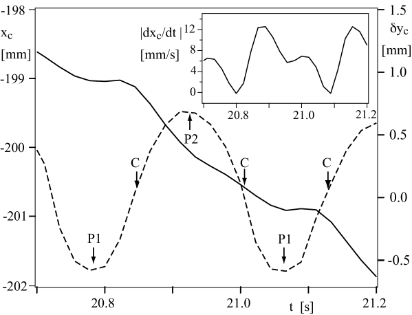
Figure 8 displays the vertical position of the cylinder as a function of time during three oscillations together with the corresponding position of the particle in the gap. In this oscillation regime, the vertical coordinate of the cylinder still follows a global linear trend with time but the velocity displays significant oscillations clearly visible in the inset of Fig.8. These variations reflect those of the drag as the cylinder moves across the gap.
The variation with time of the absolute velocity displays two minima for each period of the oscillation when the cylinder is near the first or the second wall (() and () respectively). One of the minima is close to zero and the other much shallower, suggesting a lack of symmetry of the oscillation with respect to the mid-plane; this may indicate an offset of the mean transverse location of the cylinder from the mid plane or an asymmetry of the experimental setup. The absolute velocity has also two maxima during each period: again, the maximum following the lowest minimum of the velocity is significantly shallower than the other.
IV.4 Variation of the oscillation frequency with the flow parameters.
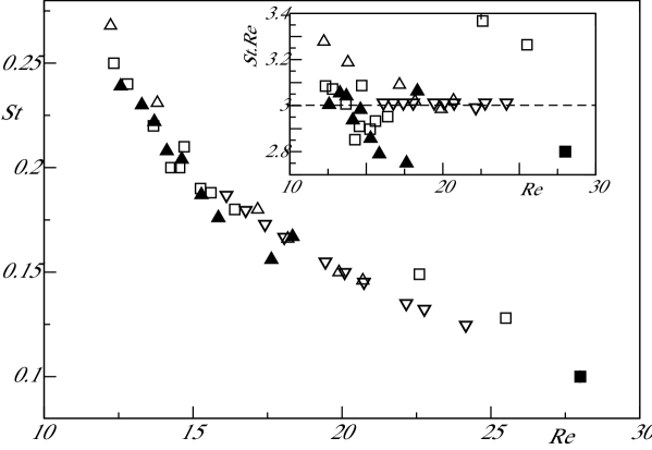
In the oscillatory regime, it is convenient to characterize the variations of the frequency by those of the dimensionless Strouhal number:
| (7) |
Figure 9 displays the variations of with the Reynolds number for all the experiments realized. Despite the use of fluids and cylinders of different characteristics, all data follow a same master curve. The value of decreases from to as increases from to . The inset of figure 9, shows that the product is nearly constant with and equal to . The frequency of the oscillation is then given by:
| (8) |
with . While depends on the fluid viscosity, on the diameter of the cylinder and on the ratio , it is thefore almost independent of the velocity of the fluid (as suggested above by Fig. 5).
V Discussion and conclusion
The experiments reported here have demonstrated that cylinders free to rotate and translate in a vertical confined Hele Shaw cell may display oscillations at Reynolds numbers , well below those corresponding to vortex shedding Williamson1996 . These oscillations are observed over a broad range of values of the confinement parameter and for different fluid viscosities . In contrast to the instability observed for tethered cylinders in a similar geometry Semin2011 , the present one induces additional oscillations at the same frequency of both the roll angle of the cylinders about their axis and their translation velocity.
A remarkable feature is the weak dependence of the frequency on the velocity while, for tethered cylinders, it varies linearly with ; is in particular the same for a cylinder sedimenting in a static fluid () and for an imposed mean flow (). For a given velocity the frequency is also significantly smaller than for a tethered cylinder and the maximum amplitude of the oscillations of the transverse velocity is reached at a lower Reynolds number (see Fig. 6). One deals therefore with a very different type of instability.
Quantitatively, is related to , and by Eq. (8). This formula implies that is proportional to the inverse of the characteristic viscous diffusion time over the diameter of the cylinder; the proportionality coefficient accounts for the blockage of the flow by the cylinder. In terms of dimensionless variables, the Strouhal number is not constant but increases from to with (Fig. 9); for tethered cylinders, instead, varies slowly and is significantly higher (). Here, the relevant combination is the product of the Strouhal and Reynolds numbers which is proportional to and constant with .
These results have direct implications on the transverse velocity in the gap at large amplitudes: assuming a constant absolute value of during the oscillations, it can be estimated by . Using Eq. (8), this leads to:
| (9) |
The velocity is then also independent of the mean flow velocity (and, therefore, of the Reynolds number for a given viscosity ): this is indeed observed in Fig.6 for . Eq. 8 also predicts that increases with and decreases as the diameter increases, also in agreement with the data plotted in Fig. 6.
The variations with time of the transverse displacement in the gap and of the rolling angle are antisymmetrical with respect to the midplane: the absolute transverse and rotational velocities are the same when the cylinder moves towards a wall or away from it. This symmetry is not as well satisfied by the vertical velocity component (and therefore by the vertical drag force on the cylinder).
The above results suggest that the growth of the oscillations of the cylinder is determined by the relative values of their period and of . At low values (), momentum diffusion is fast enough so that the flow field around the cylinder reaches a quasistatic profile identical to that of a fixed cylinder at the same location. At high frequencies (), there is a phase shift between the motion of the cylinder and the corresponding variations of the flow and pressure fields (particularly in quasiparallel flow regions in the gaps between the cylinder and the walls). At Reynolds numbers large enough (here ) so that non linear terms appear, the resulting force on the cylinder may then change sign due to the phase shift and amplify the oscillations instead of damping them.
At the largest values of the confinement parameter , more complex dynamical phenomena were observed. In addition to the instability reported above, the cylinder displayed flutter with lower frequency oscillations of its angle with respect to the horizontal and of its lateral position. Numerous studies have analyzed similar motions involving the coupling between the vertical motion of objects and lateral oscillations: these are encountered in such problems as the fluttering motion of falling leaves or paper sheets Tanabe1994 ; Belmonte1998 or that of bubbles rising in a liquid Magnaudet2000 . It will be necessary in future work to quantify the effect of the confinement on these observations and consider the low Reynolds limit.
Finally, we considered only cylinders of length close to the width of the cell. With shorter cylinders for which , the bypass of the flow between the tips of the cylinders and the lateral walls will reduce the influence of the flow blockage and thus influence the motion. This, too, represents an important parameter of the problem.
Acknowledgements.
We thank R. Pidoux, L. Auffay and A. Aubertin for realizing and developing the experimental set up and B. Semin for his careful reading of the manuscript and his useful comments. We acknowledge the RTRA Triangle de la Physique and the LIA PMF-FMF (Franco-Argentinian International Associated Laboratory in the Physics and Mechanics of Fluids). The work of one of us (VD) was supported by a Bernardo Houssay grant allocated by the Argentinian and French ministries of research.References
- (1) R. Rusconi, S. Lecuyer, L. Guglielmini and H. Stone, “Laminar flow around corners triggers the formation of biofilm streamers,” J. R. Soc. Interface 7, 1293–1299 (2010).
- (2) N. Autrusson, L. Guglielmini, S. Lecuyer, R. Rusconi and H. A. Stone, “The shape of an elastic filament in a two-dimensional corner flow,” Phys. Fluids 23 (2011).
- (3) A.S. Dvinsky and A.S Popel, “Motion of a rigid cylinder between parallel plates in Stokes flow. Part 1: motion in a quiescent fluid and sedimentation,” Computers andFluids 15, 391–404 (1987).
- (4) A.S. Dvinsky and A.S Popel. ‘Motion of a rigid cylinder between parallel plates in Stokes flow. Part 2: Poiseuille and Couette flow,” Computers & Fluids 15, 405–419 (1987).
- (5) E. Eklund and A. Jernqvist, “The motion of a neutrally buoyant circular cylinder in bounded shear flows,” Chem. Engng. Sci. 49, 3765–3772 (1994).
- (6) H.H. Hu, “Motion of a circular cylinder in a viscous liquid between parallel plates,” Theoret. Comput. Fluid Dynamics 7, 441–455 (1995).
- (7) H. Faxén, “Forces exerted on a rigid cylinder in a viscous fluid between two parallel fixed planes,” Proc. R. Swed. Acad. Eng. Sci. 187, 1–13 (1946).
- (8) A.B. Richou, A. Ambari, and J.K. Naciri, “Drag force on a circular cylinder midway between two parallel plates at very low Reynolds numbers. Part 1: Poiseuille flow (numerical),” Chem. Eng. Sci. 59, 3215–3222 (2004).
- (9) A. B. Richou, A. Ambari, M. Lebey, and J. K. Naciri, “Drag force on a cylinder midway between two parallel plates at . Part 2: moving uniformly (numerical and experimental),” Chem. Eng. Sci. 60, 2535–2543 (2005).
- (10) S. Champmartin, A. Ambari and N. Roussel, “Flow around a confined rotating cylinder at small Reynolds number,” Phys. Fluids 59, 103101 (2007).
- (11) H. Juarez, L.R. Scott, R. Metcalfe, B. Bagheri, “Direct simulation of freely rotating cylinders in viscous flows by high-order finite element methods,” Computers and Fluids 29, 547–582 (2000).
- (12) M. Sahin and R. G. Owens, “A numerical investigation of wall effects up to high blockage ratios on two-dimensional flow past a confined circular cylinder,” Phys. Fluids 16, 1–25 (2004).
- (13) L. Zovatto and G. Pedrizetti, “Flow about a circular cylinder between parallel walls,” J. Fluid Mech. 440, 1305–1320 (2001).
- (14) D. Shiels, A. Leonard and A. Roshko, “Flow-induced vibration of a circular cylinder at limiting structural parameters,” J. Fluids Struct. 15, 3–21 (2001).
- (15) C.H.K. Williamson and R. Govardhan, “A brief review of recent results in vortex-induced vibrations,” J. Wind Eng. Ind. Aerodyn. 96, 713–735 (2008).
- (16) M. P. Païdoussis, S.J. Price, E. de Langre, “Fluid-Structure Interactions - Cross-Flow-Induced Instabilities,” Cambridge University Press, Cambridge, UK (2011).
- (17) B. Semin, A. Decoene, J.P. Hulin, M.L.M. Francois and H. Auradou, “New oscillatory instability of a confined cylinder in a flow below the vortex shedding threshold,” J. Fluid Mech. 690, 345–365 (2012).
- (18) B. Semin, J-P. Hulin and H. Auradou, “Influence of flow confinement on the drag force on a static cylinder,” Phys. Fluids 21, 103604 (2009).
- (19) C.H.K. Williamson, “Vortex dynamics in the cylinder wake,” Annu. Rev. Fluid. Mech. 28, 477-539 (1996).
- (20) Y. Tanabe and K. Kaneko, “Behavior of a falling paper,” Phys. Rev. Lett. 73, 1372–1375 (1994).
- (21) A. Belmonte, H. Eisenberg and E. Moses, “From flutter to tumble, Inertial Drag and Froude Similarity in Falling Paper,” 81, 345–348 (1998).
- (22) J. Magnaudet and I. Eames, “The motion of high-Reynolds-number bubbles in inhomogeneous flows,” Annu. Rev. Fluid Mech. 32, 659–708 (2000).