Structural phase transitions in multipole traps
Abstract
A small number of laser-cooled ions trapped in a linear radiofrequency multipole trap forms a hollow tube structure. We have studied, by means of molecular dynamics simulations, the structural transition from a double ring to a single ring of ions. We show that the single-ring configuration has the advantage to inhibit the thermal transfer from the rf-excited radial components of the motion to the axial component, allowing to reach the Doppler limit temperature along the direction of the trap axis. Once cooled in this particular configuration, the ions experience an angular dependency of the confinement if the local adiabaticity parameter exceeds the empirical limit. Bunching of the ion structures can then be observed and an analytic expression is proposed to take into account for this behaviour.
I Introduction
In the wide range of radiofrequency (rf) traps, quadrupole traps take a particular place due to the parabolic rf potential they create and to the harmonic pseudo-potential it generates. In contrast, higher order traps show a more ”rectangle” shape of the rf electric field which induces a flat pseudo-potential well with a reduced rf-driven micromotion in the center of the trap Gerlich, (1992). This feature finds its application in the spectroscopy of cold molecular samples Wester, (2009) or in the interrogation of the hyperfine transition of a large atomic sample for frequency metrology Prestage & Weaver, (2007), the ions being cooled by collisions with a buffer gas.
Laser-cooling of ions trapped in multipole traps has only been performed very recently Okada et al., (2007) and experimental observations have demonstrated a tube-like structure for the ion organization Okada et al., (2009). This self-organization in empty core structure results from the competition between Coulomb repulsion and a confining force very soft in the center of the trap and stiffer towards the walls. For large sample, this behavior is confirmed by the density profile deduced in the cold charged fluid limit Champenois, (2009) and for smaller ones, by simulations of the equilibrium structures Okada et al., (2007); Calvo et al., (2009); Yurtsever et al., (2011). For a large number of ions trapped in a linear multipole trap, the general structure of a crystallized sample is a set of concentric tubes for which the revolution axis is the longitudinal trap axis. The evolution of the structure with the number of ions and the trapping parameters is extensively studied in Yurtsever et al., (2011).
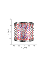
As an example, figure 1 shows the simulated structure of 1000 cold calcium ions inside the pseudo-potential of a linear octupole trap, laser-cooled to the Doppler limit temperature of 0.5 mK.
 |
 |
For the same trapping parameters and a smaller number of ions, the structure reduces to a single tube, formed of parallel rings of ions aligned along the trap axis. For a decreasing number of ions, the tube reduces to two rings then to a single ring. Ring- or tube-like structures offer the possibility to study dynamics in a two dimensional configuration. Furthermore, ion rings have symmetry properties that can be exploited in high-resolution spectroscopy. Among these highly symmetric structures, the single ring configuration has the outstanding property to be a true two dimensional system where the motional temperature along the symmetry axis can reach the Doppler limit when the ions are laser-cooled, despite the rf-driven motion in the transversal plane Champenois et al., (2010). A previous numerical study Marciante et al., (2010) of the cooling properties of ion structures formed in quadrupole traps has shown that for structures of reduced spatial dimensions, Coulomb interaction does not always couple the different directions of motion of the ions. This decoupling inhibits the thermal transfer between the decoupled directions of the motion and allows to reach the Lamb-Dicke regime for the ion motion along the longitudinal trap axis Champenois et al., (2010).
In the present article we use molecular dynamics simulation of laser-cooled ions in a linear octupole trap to study their structural phase transition from a two-ring to a one-ring configuration. The model used to simulate the ion dynamics is described in section II together with some brief reminders on linear multipole traps. Section III presents an analysis of the structural transition itself and enlightens the role of the rf-driven motion on this transition. In section IV, we extend our study by increasing the adiabaticity parameter beyond the empirical limit.
II Framework of the model
The numerical simulations use molecular dynamics, based on the symplectic velocity-Verlet algorithm to integrate Newton’s equations. We have simulated the dynamics of a set of 100 ions in the potential of a linear octupole trap, cooled by Doppler laser-cooling. Ions are thus subject to conservatives forces deriving from the trap electric potential and the Coulomb inter-ion potential, and dissipative forces due to Doppler cooling. The general form for the ideal rf potential of a linear -pole trap can be written in polar coordinates like
| (1) |
where is the amplitude of the rf potential applied to the rods, oscillating at frequency , is the inner radius of the trap, and is the electric charge of the ions. Unless otherwise specified , we use the potential of an octupole trap (2) to run the simulations. This rf potential induces an rf-driven motion which produces a ponderomotive force, which leads to the radial confinement of the ions. It can be derived from the static pseudo-potential Gerlich, (1992):
| (2) |
The motion in this pseudo-potential has a time scale larger than an rf period and is called macro-motion.
The axial confinement is achieved by a harmonic static potential well characterized by the frequency , which scales like . Obeying Laplace’s law, this static potential has a deconfining contribution in the radial plane. Hence, for each ion of mass and position , the total trapping potential writes:
| (3) |
When the order of the multipole is higher than , the deconfining contribution of the axial confinement leads to a shift of the minimum of the trapping potential in the radial plane, from the centre to a circle of radius :
| (4) |
Hence, contrary to a quadrupole trap configuration, the local minimum of the trapping potential is no more superposed to a node of the rf electric field Marciante et al., (2011). Throughout this article, the confinement parameters and number of ions are such that the ions sit very close to the potential minimum and they do undergo micro-motion.
The Coulomb interaction is taken into account by the total pair interaction potential, which writes:
| (5) |
where is the number of ions and is the relative distance between ions and . The Doppler laser-cooling is modeled using velocity kicks simulating the ion’s recoil, which happens depending on the probability laws of absorption (given by the stationary solution of the optical Bloch equations) and emission (given by the exponential decay law). For symmetry reasons, laser-cooling is applied in the three directions of the trap. Details about the model we used for the cooling are given in Marciante et al., (2010).
Initial conditions are prepared by giving to each ion an initial position randomly chosen in the inner 10% of the radius of the trap and a random velocity obeying a thermal distribution corresponding to 1 K. Ions are trapped by the rf electric field and are subject to Doppler cooling. The system is ready for further simulations when the temperatures are stationary. The temperature is one of the relevant parameters to get insight into ion dynamics. As the rf-driven motion is not a thermal motion, it has to be subtracted from the velocities before computing the temperature Prestage et al., (1991); Schiffer et al., (2000). In practice, this is done by averaging the velocity of the ions over an rf period. Each averaged component of the velocity is then taken into account to define the temperature associated to each direction of the motion. Explicit details about the computation of the temperatures can be found in Marciante et al., (2010).
All the forthcoming results assume perfect trap operation and neglect defects of the potential due to patch potential and/or misalignments of the electrodes as well as collisions with the residual gas. Patch potentials with a highly non-uniform spatial repartition could destroy the highly symmetric structure formed by few ions in a linear multipole trap. For high precision spectroscopy in multipole trap, more extra electrodes than for a line in quadrupole trap may be required to compensate for patch potentials and their gradient. Misalignment of the electrodes has been identified in a 22-pole trap Otto et al., (2009) as responsible for 10 extra potential minima, which cause bunching of the ions in these local potential wells. As for collisions, they may perturb the formation process of the crystal but the trapping conditions chosen for these studies imply a strong confinement in the axial and in the radial direction, of the same order of magnitude as the one met in quadrupole trap. Therefore, the stationary structures described in this article should survive to collisions like ion chains do. This strong confinement may seem unrealistic regarding the smooth profile of the trapping field in the center of the trap. The scaling law for the rf electric field in an octupole is , and to reach a value of m with MHz and MHz like chosen in the following, it takes an amplitude equal to 208 V in a 0.5 mm inner radius trap, which is very accessible. As for quadrupole trap dedicated to single ion experiment, a multipole trap able to keep a single ring stable has to be specifically designed to that purpose.
III Double-ring to single-ring structural transition
The trapping parameters are such that the Coulomb repulsion is negligible compared to the deconfining effect associated to the axial confinement and the radial position of the ions is controlled by the potential minimum . Depending on the number of ions and the applied axial potential, the stationary structure is a single or a double ring. By stability consideration, one can show that there is a critical radius below which the equilibrium configuration is a double ring Champenois, (2009). This critical radius only depends on and through
| (6) |
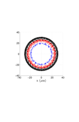
For a set of 100 ions and MHz, the stability critical radius is m. The rf electric potentiel is chosen such that the radius is m and the ions organize themselves in two rings of 50 ions separated by an axial distance of about m. This double-ring structure can be seen on figure 2, for an rf phase corresponding to the maximal amplitude of the micro-motion.
 |
 |
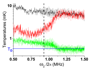
The pattern formed by the two ion rings is equivalent to an annular zig-zag structure Waki et al., (1992), the positions of two consecutive ions being on different sides of the plan. This perfect annular zig-zag is obtained by choosing an even number of ions. In this configuration, the temperature associated with the axial component of the motion is mK (see figure 3). If the velocity of the ions is expressed in cartesian coordinates, the and temperatures are identical and are approximately equal to 12 mK. The difference between these values is attributed to a partial thermalization of the degrees of motion, the higher temperature being induced by rf-driven motion in the radial plane. This motion induces rf-heating by which the kinetic energy of the rf-driven motion is transferred to the macro-motion Ryjkov et al., (2005). It also reduces the Doppler cooling efficiency by the Doppler shift on the cooling transition. The temperature discrepancy shows that the Coulomb coupling in the two-ring structure is not strong enough to thermalize the motion in the radial plane with the motion along the axis Marciante et al., (2010). Inside the radial plane itself, the use of cylindrical coordinates reveals an important discrepancy in the temperature associated to the radial motions ( mK) and the one associated to the tangential motion ( mK, see figure 3).
Starting from this configuration, we study the double to single ring transition. To that purpose, the characteristic frequency of the axial confinement , is slowly increased from 0.5 MHz to 1.5 MHz. At the same time, the amplitude of the rf electric field is raised to balance the enhancement of the static deconfining effect in the radial plane, keeping the minimum of the trapping potential, , and thus the radius of the ring, constant (see equation 4). For a constant number of ions, the structural transition is expected from equation 6 to take place for MHz. It is verified that the variation of the trapping parameters is sufficiently slow to consider the system to be in a stationary state during the simulation. Particular cares are taken for values above 0.92 MHz for which the increase of the confinement parameters is halted every 0.1 MHz, by time periods of 10 ms.
The structural transition is first monitored by the distance between the center of mass (c.m.) of the two rings, , given on the left axis of figure 4, as a function of the characteristic frequency . The value for which the two rings merge is in good agreement with the theoretical frequency of 0.93 MHz, for which the structural transition is predicted.
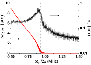
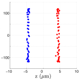
The standard deviation of the axial component of the ions’ positions from the c.m. position is also plotted on figure 4. For MHz, the standard deviation is due to the axial thermal motion around the equilibrium position. Increasing , the axial temperature (shown on figure 3) drops while the local steepness of the potential in the axial direction is increased. Hence, the axial dispersion on ions’ positions which is due to thermal motion is expected to decrease when grows. Figure 4 shows that it becomes maximum around the structural transition before decreasing to a lower value than the initial one. To understand the transition process, we focus on the ion organization just before the structural transition. While the two rings are getting closer, a distortion of the ring structures progressively appears, visible on figure 5 and stationary over the rf period. The distortion does not affect the equilibrium radius of the structures but the axial inter-ion distance is smaller for ions localized close to the rf electrodes than for those which are trapped far from the electrodes (with the convention defined by equation 1, electrodes are at angular positions ). This behaviour is attributed to micro-motion whose amplitude has the analytic form:
| (7) |
When ions are localized in front of an rf-electrode, the micro-motion amplitude is almost exclusively radial and has no significant consequence on the relative distance of two neighbouring ions belonging to different rings. On the contrary, when ions are localized at an inter-electrode angular position, the micro-motion is mostly tangential to the ring structure and depends like on the ion angular position. Two neighbouring ions, separated by an angle , do not have the same tangential amplitude of micro-motion, producing an oscillation of their angular separation. Since the neighbouring ions do not belong to the same ring, this variation of angular positions brings them face to face, increasing their Coulomb repulsion in the axial direction. The comparison with simulations run in the pseudo-potential (equation 2) confirms that this behaviour is induced by the rf motion.
The evolution of the distortion during the increase of explains the increase of standard deviation roughly situated between 0.75 MHz and 0.93 MHz (Figure 4). When the transition frequency is reached, the c.m. of the two structures match roughly, but the standard deviation takes its maximal value, showing that the structure is not yet a planar ring. For higher values of , the standard deviation shows a steep downward slope, until a frequency value slightly lower than 1 MHz. The structure can then be considered as a planar single-ring structure.
The distortion of the structure described above and the coupling between the tangential and axial component of motion it induces, explain the initial discrepancy between the radial and tangential temperatures when the structure is a double-ring (see figure 3). The axial motion being not subjected to micro-motion, it can reach lower temperature than the motions in the radial plane. The coupling between axial and tangential components of the motion allows to dissipate a part of the tangential thermal kinetic energy through the axial cooling. As the frequency is increased, the temperature increases progressively and meets the temperature associated to the radial directions, . At the same time, the axial temperature shows a steeper drop between 1 MHz and 1.25 MHz, reaching the Doppler limit temperature at the frequency where the two other temperatures join. This behaviour suggests that the axial component of the motion of the ions is then decoupled from the two transverse directions, like expected for a full two dimensional system Marciante et al., (2010).
The comparison between Figures 4 and 3 shows that for this small 100-ion system, informations on the dimensionality of the system given by the variation of the ions’ positions, , and the temperatures of the system do not coincide. The decoupling observed on the temperature arises when the parameter already shows a planar structure. As a consequence, each of these parameters may be a relevant criteria to determine the structural phase transition.
IV Above the adiabatic limit
The single ring structure presented in the preceding section seems very promising for applications such high precision spectroscopy, quantum information or for metrological applications Champenois et al., (2010); Olmos et al., (2009). For all of these, it is mandatory to reduce the amplitude of motion of the ions to below the chosen transition wavelength (the Lamb-Dicke regime Wineland et al., (1978)) to cancel the first order Doppler effect. For trapped ions, Doppler laser-cooling is sufficient if the trapping frequency along the laser propagation direction is large enough. In practice, for calcium ions cooled to the Doppler limit, a motional frequency of 1 MHz allows the ions to reach the Lamb-Dicke regime for an optical transition. One of the main drawbacks of the ring structure compared to its linear counterpart, the ion chain, found in quadrupole traps is the non null rf-driven motion (micro-motion) at their equilibrium positions. Figure 3 shows that in the single ring configuration, the motion along the axis is decoupled from the motion in the radial plane where micro-motion, and thus rf-heating, take place. The Lamb-Dicke regime can thus be reached for laser propagating along the trap axis.
To quantify the impact of the micro-motion on the ion dynamics and laser cooling, the Mathieu parameter , relevant for this issue in quadrupole traps, can be extrapolated to multipole trap and is then related to the more general concept of adiabaticity of the trajectories Gerlich, (1992). The adiabaticity parameter depends on the radial position of the ions inside the trap and at the potential minimum , it takes the simple expression Champenois, (2009):
| (8) |
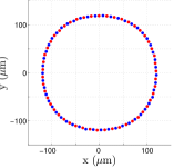
It has been demonstrated, numerically and experimentally in a 22-pole Mikosch et al., (2007, 2008); Wester, (2009), that for the trajectories are stable but few studies concern this adiabaticity parameter in the context of cold samples. In this section, we focus on the role of the micro-motion on the self-organization of the ions and relate it to the adiabaticity parameter. Figure 6 shows the single ring structure formed by 100 ions located at the same radial potential minimum and trapped by an axial potential characterized by equal to 1 MHz (), 2 MHz () and 3 MHz (). For increasing , we observe a bunching of the ions at the inter-electrode angular positions.
 |
 |
 |
 |
 |
 |
 |
 |
 |
This bunching is not observed in the pseudo-potential approach of the trapping electric field and is attributed to the micro-motion of the ions. Some insight in the role of micro-motion can be gained by considering a cold sample sitting close to , where the radial trapping potential can be approximated by a local harmonic potential. Assuming a null potential for , it can be written like
| (9) |
with the characteristic frequency Champenois, (2009). The ion motion is assumed to be due only to the rf-driven micro-motion whose amplitude can be written like:
where the amplitude of the micro-motion is easily deduced from equation 7. Only the radial contribution of this motion engenders a significative potential energy variation during the rf-period. Its time average depends on the angular position like
| (11) |
and could explain the bunching observed on figure 6. To test this assumption, we have created a configuration where only two ions bunch in one of the local angular minimum potential localized around . To that purpose, we have simulated a set of 9 ions in the rf-potential of the same octupole trap, with initially set at 0.5 MHz, and slowly increased to 4 MHz, keeping m constant by increasing the rf potential. The final stable configuration is then made of seven ions and a unique pair of ions, localized at each inter-electrode angular positions.
Assuming a local description for the force responsible for the bunching, the measure of the relative distance of the ions forming the pair allows one to deduce the characteristic frequency from the equilibrium condition with the Coulomb repulsion:
| (12) |
One can also evaluate the force by deriving the time-averaged micro-motion induced potential , for an angle :
| (13) |
Writing like , one can connect the characteristic frequency to the local radial potential. The results of numerical simulations show that the predicted bunching frequency is larger than the measured frequency by a factor , all along the simulation increasing at constant . The disagreement by a factor is also observed when the same simulations are run with 13 ions in a dodecapole trap. According to the results obtained from the simulations, the local bunching caracteristic frequency is given by:
| (14) |
Eq. 14 shows how the bunching frequency depends on the characteristic trapping parameter and ring configuration. Indeed, using the dependence of the micro-motion with the position in the trap, one can show that scales like . Hence, the bunching force scales like . The dependence of this bunching force with was illustrated on figure 6 for fixed . Its dependence with for fixed can be seen on figure 7 and confirms an increase of the bunching with .

These different studies show that the so-called adiabaticity parameter is not the relevant criteria to estimate the role of micro-motion on the ion organization. Indeed, the four structures plotted on figure 7 share the same . This behaviour shows that in the general description of the ion dynamics in a multipole trap, micro-motion has a non-negligible influence not only on the thermal propoerties of the sample but also on its structural properties, and has thus to be taken into account.
V Conclusion
In this paper, we have numerically studied the double-ring to single-ring structural transition of a Doppler-cooled 100-ion system in the rf potential of an octupole trap. The simulations showed that, in the double-ring configuration, the temperatures associated to each component of the motion expressed in cylindrical coordinates are different. In our initial configuration, the tangential temperature is lower than the radial one by almost one order of magnitude. This is attributed to a coupling of the tangential motion to the axial one, which is efficiently Doppler-cooled due to the absence of rf-driven motion along the axial direction. When the double-ring structure is compressed, the c.m. of each ring merge at the predicted transition frequency but the structure shows a distorsion which is maximal at this frequency. This behaviour is attributed to the micro-motion of the ions, inducing an axial Coulomb repulsion which can be considered as a pseudo-potential between the ions of the different rings. A planar single-ring structure is thus obtained for a higher value of the predicted transition frequency. When is further increased, the axial temperature reaches the Doppler limit value showing a decoupling of the axial and transverse components of the motion.
For a cold ion system, we have also shown that it is possible to increase the adiabaticity parameter beyond the empirical limit, keeping stable ion confinement. At a fixed ring radius, increasing the adiabaticity parameter results in a bunching of the structure, for which an expression of the local bunching frequency is proposed. We have also shown that changing the ring radius at constant value of the adiabaticity parameter leads to the emergence of the bunching phenomenon.
References
- Gerlich, (1992) Gerlich, D. 1992. Inhomogeneous rf fields: a versatile tool for the study of processes with slow ions. Advances in Chemical Physics Series, 82.
- Wester, (2009) Wester, Roland 2009. Radiofrequency multipole traps: tools for spectroscopy and dynamics of cold molecular ions. Journal of Physics B: Atomic, Molecular and Optical Physics, 42(15):154001 (12pp).
- Prestage & Weaver, (2007) Prestage, J.D., & G.L. Weaver 2007. Atomic Clocks and oscillators for Deep-Space navigation and Radio Science. Proceedings of the IEEE, 95(11):2235 – 2247.
- Okada et al., (2007) Okada, Kunihiro, Kazuhiro Yasuda, Toshinobu Takayanagi, Michiharu Wada, Hans A. Schuessler, & Shunsuke Ohtani 2007. Crystallization of Ca+ ions in a linear rf octupole ion trap. Phys. Rev. A, 75(3):033409.
- Okada et al., (2009) Okada, K., T. Takayanagi, M. Wada, S. Ohtani, & H. A. Schuessler 2009. Observation of ion Coulomb crystals in a cryogenic linear octupole rf ion trap. Phys. Rev. A, 80(4):043405.
- Champenois, (2009) Champenois, C 2009. About the dynamics and thermodynamics of trapped ions. Journal of Physics B: Atomic, Molecular and Optical Physics, 42(15):154002 (9pp).
- Calvo et al., (2009) Calvo, F., C. Champenois, & E. Yurtsever 2009. Crystallization of ion clouds in octupole traps: Structural transitions, core melting, and scaling laws. Phys. Rev. A, 80(6):063401.
- Yurtsever et al., (2011) Yurtsever, E., E. D. Onal, & F. Calvo 2011. Structure and dynamics of ion clusters in linear octupole traps: Phase diagrams, chirality, and melting mechanisms. Phys. Rev. A, 83(5):053427.
- Champenois et al., (2010) Champenois, C., M. Marciante, J. Pedregosa-Gutierrez, M. Houssin, M. Knoop, & M. Kajita 2010. Ion ring in a linear multipole trap for optical frequency metrology. Phys. Rev. A, 81(4):043410.
- Marciante et al., (2010) Marciante, M., C. Champenois, A. Calisti, J. Pedregosa-Gutierrez, & M. Knoop 2010. Ion dynamics in a linear radio-frequency trap with a single cooling laser. Phys. Rev. A, 82(3):033406.
- Marciante et al., (2011) Marciante, M., C. Champenois, J. Pedregosa-Gutierrez, A. Calisti, & M. Knoop 2011. Parallel ion strings in linear multipole traps. Phys. Rev. A, 83(2):021404.
- Prestage et al., (1991) Prestage, J. D., A. Williams, L. Maleki, M. J. Djomehri, & E. Harabetian 1991. Dynamics of charged particles in a Paul radio-frequency quadrupole trap. Phys. Rev. Lett., 66(23):2964–2967.
- Schiffer et al., (2000) Schiffer, J.P., M. Drewsen, J.S. Hangst, & L. Hornekær 2000. Temperature, ordering,and equilibrium with time-dependent confining force. PNAS, 97:10697.
- Otto et al., (2009) Otto, R., P. Hlavenka, S. Trippel, J. Mikosch, K. Singer, M. Weidemueller, & R. Wester 2009. How can a 22-pole ion trap exhibit 10 local minima in the effective potential? J. Phys. B, 42:154007.
- Waki et al., (1992) Waki, I., S. Kassner, G. Birkl, & H. Walther 1992. Observation of ordered structures of laser-cooled ions in a quadrupole storage ring. Phys. Rev. Lett., 68(13):2007–2010.
- Ryjkov et al., (2005) Ryjkov, Vladimir L., XianZhen Zhao, & Hans A. Schuessler 2005. Simulations of the rf heating rates in a linear quadrupole ion trap. Phys. Rev. A, 71(3):033414.
- Olmos et al., (2009) Olmos, B., R. González-Férez, & I. Lesanovsky 2009. Fermionic Collective Excitations in a Lattice Gas of Rydberg Atoms. Phys. Rev. Lett., 103(18):185302.
- Wineland et al., (1978) Wineland, D. J., R. E. Drullinger, & F. L. Walls 1978. Radiation-Pressure Cooling of Bound-Resonant Absorbers. Phys. Rev. Lett., 40(25):1639.
- Mikosch et al., (2007) Mikosch, J., U. Frühling, S. Trippel, D. Schwalm, M. Weidemüller, & R. Wester 2007. Evaporation of Buffer-Gas-Thermalized Anions out of a Multipole rf Ion Trap. Phys. Rev. Lett., 98(22):223001.
- Mikosch et al., (2008) Mikosch, J., U. Frühling, S. Trippel, R. Otto, P. Hlavenka, D. Schwalm, M. Weidemüller, & R. Wester 2008. Evaporation of trapped anions studied with a 22-pole ion trap in tandem time-of-flight configuration. Phys. Rev. A, 78(2):023402.