Theory of single-electron heat engines coupled to electromagnetic environments
Abstract
We introduce a new class of mesoscopic heat engines consisting of a tunnel junction coupled to a linear thermal bath. Work is produced by transporting electrons up against a voltage bias like in ordinary thermoelectrics but heat is transferred by microwave photons, allowing the heat bath to be widely separated from the electron system. A simple and generic formalism capable of treating a variety of different types of junctions and environments is presented. We identify the systems and conditions required for maximal efficiency and maximal power. High efficiencies are possible with quantum dot arrays but high power can be achieved also with metallic systems.
pacs:
73.23.Hk, 73.50.Lw, 72.70.+m, 44.40.+aI Introduction
Conversion of heat to work, and, in particular, recovery of waste heat produced by electronic components is a problem of great and ever increasing importance. Solid-state thermoelectric systemsali are ideally suited for this purpose since they are easily integrated with the rest of the circuitry on the microchip. Mesoscopic heat transfer devices are a promising class of thermoelectric systems due to their ease fabrication, control, and measurement,rmp and because sharp features in the energy spectrum, a requirement for efficient operation,mahan are readily available. Due to their small size they can also be used to study foundational issues, such as the importance of fluctuationshanggi and the fundamental limits of heat engine performance.qubit
Arguably the simplest mesoscopic heat engine consists of a single-level quantum dot placed between two metallic leads held at different temperatures and voltages.linke Positioning the dot level far enough from the Fermi levels of the leads enables the electrons to flow against the voltage bias while carrying heat from hot to cold. Thermoelectric properties of weakly coupled quantum dots have also been experimentally studied.exp93 ; exp97 ; exp07 ; exp11 This type of device operates as a heat engine by generating electrical current and transferring heat between the same two reservoirs. A recent modificationrafa1 ; rafa2 of this scheme makes the charge and heat currents flow along different pathways by introducing a third reservoir: charge is transported between two reservoirs at the same temperature, while the third reservoir, at a different temperature, is Coulomb-coupled to the transport electrons and supplies the thermal fluctuations driving the heat engine.
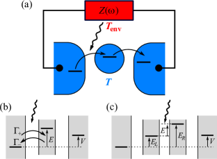
Here we introduce a new type of mesoscopic heat engine, sketched in Fig. 1(a). It consists of one or more quantum dots or metallic dots between two electronic leads at the same temperature but with a voltage bias . The leads are connected to an external circuit with temperature and impedance . If the tunnel coupling for one of the junctions is small enough, a tunneling electron will exchange energy with the electromagnetic environment, and with a proper choice of parameters it is then possible to achieve a net current against the voltage bias. This system is similar in spirit to the devices of Refs. rafa1, ; rafa2, but instead of a direct Coulomb interaction between the electrons in the transport system and in the heat bath, in our proposal the coupling is mediated by microwave photons. Photonic heat conduction in electronic circuits has been investigated in recent years both theoreticallyschmidt ; niscooler ; teemu1 ; teemu2 ; teemu3 ; hekking and experimentally,jukka1 ; jukka2 while previously studied single-electron devices for thermal applications include a thermometerrmp ; cbt , a coolerniscooler , and a heat diode.diode There are also theoretical proposals for three-reservoir heat engines where the electrons are driven by a coupling to a phonon bath.ora ; peng
A significant advantage of the photonic coupling compared to Coulombic or phononic interaction is that the two parts of the circuit with different temperatures can be located arbitrarily far apart. One can imagine a scenario where the external circuit is a relatively large device which performs some useful function but at the same time produces excess heat. Our engine can recover a part of this heat and feed it back to the main device as electrical power.
We show that in an optimal configuration the electrical current in different types of junction systems is given by a single concise formula, Eq. (6). Then a junction between two quantum dots is shown to be ideal in terms of efficiency while all junction types, involving either metals or quantum dots, are able to deliver approximately equal maximal power production.
The rest of the paper is organized as follows. In Sec. II we present the theory for electron tunneling in a linear external environment. In Sec. III we consider bath-assisted transport in junction arrays and conclude that in an appropriate limit the current is given by Eq. (6) for a variety of different systems. The heat engine characteristics of different junction types are studied in detail in Sec. IV, with a particular emphasis on performance under maximum power conditions. In Sec. V we summarize the results and consider experimental prospects.
II Coupling to the environment
The exchange of energy between the tunneling electron and the external environment is treated with the so-called theory. A thorough account of this formalism is given in Refs. naz1, ; naz2, , and in this Section we only present the results relevant for the present study. theory, and therefore also our present work, rests on two fundamental requirements: i) it is assumed that the coupling between the different electron systems is weak enough and that the temperature of the electrons or the environment is high enough so that transport can be adequately described by the lowest-order Fermi golden rule, and ii) it is assumed that the environment relaxation is much faster than the tunneling rate. Then within theory the tunneling rate between electron systems and through a junction, that is, a single insulating barrier, is given by the Fermi golden rule formula with the energy-conserving function replaced by , the probability density to exchange energy with the environment. Thus we havenaz1 (with )
| (1) |
where . For the electron density we consider two cases, a single-level quantum dot with , and a metal with where is the density of states and is the Fermi function. Similarly the hole density is for dots and for metals. Note that in the quantum dot case we assume that dot is occupied and dot is empty, otherwise the rate would vanish. The tunneling matrix element between the initial and final states is , which is taken here to be energy independent. The Fermi level of a metal or the single level of a quantum dot is with possible Coulomb charging energies absorbed into it. The heat current emitted by the environment during the tunneling process is obtained from the rate formula by weighing the integral with :
| (2) |
The function for an electromagnetic environment can be determined by a circuit theory analysis of the system. If the junction, which itself has some capacitance , is coupled to an environment with impedance , the total impedance over the junction is and in parallel, that is, . We will omit the rather complicated general expression for . For our purposes it is sufficient to note that it only depends on the environment temperature and the real part of . Since is a probability density its integral is normalized to unity, and additionally the detailed balance for the environment requires thatnaz1 .
When presenting numerical results we will consider a simple and prototypical environment, namely an ohmic resistor with impedance . We further assume the high-impedance limit where is the largest time scale of the system. Then the function is given asnaz1
| (3) |
where is the charging energy of a junction with capacitance and .
III Currents in junction systems
Thermoelectric power generation in a three-reservoir single-electron device requires at least one environment-coupled tunnel junction, and we will now consider systems with one, two, or three junctions in series. The concrete realizations of these systems are zero, one, or two (quantum or metallic) dots placed between two metallic reservoirs. We work within the framework of theory, and thus assume weak coupling and fast environment relaxation, as explained in Sec. II.
Let us start with a single junction with no dots between two noninteracting metallic leads at temperature . The junction is coupled to an electromagnetic environment with an arbitrary and temperature . The tunneling rate for the positive direction, from left () to right (), is and the rate in the opposite direction is . With the voltage bias , Eq. (1) gives the current as
| (4) | ||||
where and . The subscript for the current denotes the fact that there are no dots in the system. We use a convention where a positive voltage means that electrons have a higher energy in the right lead and a positive current means that electrons travel, on the average, from left to right. Therefore if and have the same sign, that is, the generated power is positive, heat is converted to electrical work and the device operates as a heat engine. For the present case the bracketed term in Eq. (4) has a sign that is opposite to the sign of and therefore . This simple junction cannot produce thermoelectric power. One way to understand this failure is to think of the system as a Brownian motorreimann which is driven by thermal fluctuations due to the external environment. However, these fluctuations do not intrinsically have any preferred direction and therefore the noise must be rectified by the electron transport system in order to generate net power.rafa2 Rectification requires a nonlinear current–voltage characteristic but the simple junction (without the environment coupling) is linear. Therefore a nonlinearity must be introduced into the transport system, and here we do it by adding a (quantum or metallic) dot between the two leads. We further assume that the Coulomb repulsion within the dot is so strong that it can only be empty (with probability ) or singly occupied (with probability ). The Fermi level of the metallic dot or the single-particle level of the quantum dot is at energy , with Coulomb energy included; see Fig. 1(b). Now the system has two junctions, and the tunneling rates through the left and right junction are and , respectively. Instead of Eq. (4), the current is given by . The probabilities can be solved from the master equation in the steady state, . This gives the current for the one-dot system as
| (5) |
If the two junctions are identical, symmetry of the system implies that there is no thermally induced net current for , and a calculation with Eq. (1) shows that there can be no power production for any . For instance, in the case of a quantum dot the numerator of Eq. (5) is proportional to . For the first and the second Fermi function are smaller that the third and the fourth, respectively, implying . To arrive at the preceeding expression the functions for the two junctions must be identical, and therefore unequal environmental couplings are required for power production.
Since both junctions are connected to the same external circuit, the only way they can have different functions is that the junction capacitances, and , are unequal. In that case circuit theory analysisnaz1 shows that the total impedance over junction is , where and , with . In other words, the only difference to the single junction case is that the external impedance seen by junction is effectively reduced by a factor . Thus a maximal difference between the functions of the two junctions can be obtained when the capacitances have different orders of magnitude. If, for example, with a small left-side capacitance , we have , , and . In this limit the left junction is coupled to the environment with energy while the coupling of the right junction is suppressed by a factor of . Note however that the charging energy of the dot is which must still be large enough to prevent a multiple occupation of the dot. To simplify Eq. (5) we note that since now the right junction is effectively decoupled from the environment, detailed balance requires . This relation can, of course, be also derived from Eq. (1) with . Furthermore, a junction with a small capacitance is usually also weakly transmitting and therefore it is consistent to assume that implies . Then we obtain
| (6) |
This is the main equation of the present paper. Below we argue that it applies also to more generic junction systems and therefore we have dropped the subscript from . The heat engine behavior produced by this equation is examined in detail in the next section.
Let us then turn to the case of two dots in series between the leads, as depicted in Fig. 1(c). The energy levels of the left and right dot are and , respectively, and . We again assume a strong enough Coulomb repulsion so that the double dot can be either empty (probability ), or there can be one electron in the left dot (probability ) or in the right dot (probability ). The tunneling rates through the left, center, and right junction are , , and , respectively, and the current is given by . Master equation for the occupations is
| (7) | |||||
and the steady-state solution gives the current as
| (8) |
with . Similarly to the one-dot case, we now assume that the central junction between the dots has a small capacitance and a small transmittance compared to the other two junctions. Thus , and since now the left and right junctions are effectively decoupled from the environment, detailed balance implies and . The expression for the current is then simplified to
| (9) |
The last term of the denominator is vanishingly small compared to the first two if and . In this limit the expression for the current is again reduced to Eq. (6). Physically this limit means that the dot levels are much below the Fermi levels of the leads and thus either of the two dots is always occupied (), leading effectively to a two-state system similar to the one-dot case. Clearly this argument could also be extended to a larger number of dots if necessary.
We have now seen that Eq. (6) is the fundamental expression for thermoelectric current in the optimal limit when only one junction is exchanging heat with the external bath and when all “idle” time spent on processes with no environment coupling can be neglected. The generality of Eq. (6) can also be intuitively seen as follows. The system is always in one of two possible states: there is an electron ready to tunnel either from left to right or from right to left through the bath-coupled junction. The probabilities of these two states are and , and the average current through the junction is therefore . On the left side of the junction there is a metal with Fermi level , or a quantum dot with a level at strongly coupled to a metal. In either case, the probability that the left side has an electron ready for tunneling is proportional to . Similarly the right side has a level at , and it is ready to receive the tunneling electron with a probability proportional to . Thus we have and analogously . Normalizing with gives and , and we arrive at Eq. (6). The existence of these two states is due to the electron–electron interaction. The noninteracting case of Eq. (4) is obtained when there is only one single state allowing electrons to tunnel at any time in either direction.
The heat current emitted by the environment can be calculated by following exactly the same steps as for the electrical current, and the result corresponding to Eq. (6) is
| (10) |
where and are the energy currents absorbed by the electron tunneling to the right and to the left, respectively, as obtained from Eq. (2). The sign difference between Eqs. (6) and (10) is due to the fact that already contain the direction of the heat flow.
IV Heat engine characteristics
As we have argued, in the optimal limit an array of one or more dots can be seen as a two-state system obeying Eqs. (6) and (10), and thus when evaluating the thermoelectric power generation in these devices it is only necessary to consider the single junction that is coupled to the electromagnetic environment. Some generic remarks about Eq. (6) can be made without any explicit model for the junction. First note that a mirror reflection of a solution with produces another solution with and therefore it is sufficient to consider the case . Next, the curve of Eq. (6) has a simple overall structure. Since the tunneling rates depend only on the level difference over the junction but not on the voltage bias , the current depends on only through the Fermi functions. Thus we see that approaches asymptotically and for large negative and positive values of , respectively. Since decreases monotonically, at some point the current vanishes. For our purposes the most important fact is that for voltages between and , and have the same sign and the device operates as a heat engine. From Eq. (6) we can solve
| (11) |
All the systems studied here have and therefore is an upper limit for while no lower limit exists. We will also see that a hot environment () implies and therefore the heat engine operates with positive and while for a cold environment () and are negative.
An important characteristic of a heat engine is the efficiency , where is the heat current from the hot bath. When we have simply but when the hot bath is the transport system and then , that is, the heat taken from the electrons is the sum of the produced power and the heat expelled to the cold environment. Thus we have
| (12) |
The fundamental upper limit for is the Carnot efficiency , where and . In this limit transport proceeds reversibly and power production is vanishingly small. Thus reaching Carnot efficiency is not a very useful goal in practice.
Another efficiency measure, widely used in the context of thermoelectric power generation, is the figure of merit . Even though the separation of heat and charge pathways makes the devices covered by our theory quite different from typical thermoelectrics, the usual definition of can still be straightforwardly applied to the present case. In the linear response limit, when and are much smaller than , we haveali
| (13) |
where the Seebeck coefficient is , electrical conductance is at , and thermal conductance is at . Generally should include all forms of heat transfer between the reservoirs, but since we are not modeling any parasitic flows they are not included in . There is a major effort in thermoelectrics research to produce systems with .ali
When an electron is transported between the leads of a thermoelectric system it always performs the same amount of work where the sign depends on the direction of tunneling. However, the amount of heat transferred between the thermal baths can vary from one tunneling event to another, and the spectrum of this energy exchange is determined both by the structure of the junction and the environment. We consider two limiting cases for the junction structure. The first is a fully energy-selective junction, where each tunneling event is accompanied by an exchange of a fixed amount of heat . A physical realization for this is a junction between two quantum dots with sharply defined energy levels separated by . The other extreme is a totally unfiltered junction where essentially any amount of heat can be exchanged. The two physical examples that we consider are a junction between a quantum dot and a metal, and a junction between two metals.
IV.1 Energy-selective junctions
A junction between two quantum dots can only exchange a fixed energy with the external bath during the tunneling events. Using Eq. (1) together with detailed balance for the environment yields
| (14) |
Similarly the heat flows from Eq. (2) are and , which imply the simple relation . Therefore at all temperatures the ratio of produced power and transferred heat is a constant , a situation known as strong coupling between particle and heat flows. Carnot efficiency can only be achieved by such strongly-coupled systems,qubit ; kedem ; broeck and in the present case this can be confirmed by noting that the stopping voltage from Eq. (11) is
| (15) |
and substituting in Eq. (12) yields . Thus Carnot efficiency implies vanishing current and power. The value for the figure of merit can be inferred directly by noting that since in Eq. (13) is evaluated at , the strong-coupling condition implies and therefore , independent of any parameters. This is another indication that energy-selective junctions can be used to construct maximally efficient thermoelectrics.
In order to investigate the physics beyond linear response and to find out the conditions that maximize the power instead of efficiency, we perform a numerical calculation and for that purpose an explicit expression for the environment spectrum is needed. Since an energy-selective junction interacts with the environment only at a single energy , the full form of the function does not generally have much significance. There is one caveat, however: Fermi golden rule, which theory is based on, is not able to treat transitions between discrete states, and therefore our approach fails if the environment and both sides of the junction are discrete. Our example environment of Eq. (3) is continuous and therefore the present approach is valid also for a junction between two quantum dots, except in the limit when becomes a discrete delta peak.
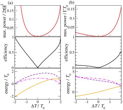
For each pair of temperatures and , the generated power from Eqs. (6) and (14) is numerically maximized with respect to the bias , the level difference , and the coupling energy , and the results are presented in Fig. 2(a). In order to estimate the maximum power achievable with this device we note that the unit of power in Fig. 2(a) is , and to find an upper limit for this quantity we model the junction between two quantum dots as a two-state system with level difference and tunnel coupling . The left and right dots must be approximate energy eigenstates, requiring that . Since for maximum power operation, we end up with . Thus the output power is strictly limited by the operating temperature. The spurious divergence of power for very large temperature differences is due to the breakdown of theory, as explained in the preceeding paragraph.
We remark that this energy-selective system is very similar to the one studied in Ref. rafa1, . The physical implementations are rather different, with the system of Ref. rafa1, requiring a total of four quantum dots while for our device two dots are sufficient, but the structures of the energy transfer processes are fundamentally identical, leading to very similar performance figures.
IV.2 Unfiltered junctions
Junctions which do not restrict the amount of energy exchanged between the tunneling electron and the environment will be called unfiltered. We concentrate on a system where the other side of the junction is a quantum dot and the other side is a metal, but at the end of the Section we also briefly consider a junction between two metals. For a metal–quantum dot junction Eq. (1) gives
| (16) |
where . This form shows immediately that and thus . Linearizing Eqs. (6) and (10) then yields the figure of merit from Eq. (13) as
| (17) |
where , , , and . These definitions show that if consists of a pair of delta peaks at energies , then in the limit we have and therefore this kind of environment is able to mimic the effect of an energy-selective junction. However, in this limit , and thus the power , scales as . A more detailed analysis shows that beyond a linear increase in corresponds to an exponential suppression of generated power. This should be contrasted to the energy-selective junction where the infinite is due to the idealized assumption of perfectly sharp energy levels. In reality the levels are broadened and the figure of merit is finite. However, when the level width is decreased, power is reduced roughly inversely, and not exponentially, with .linke_max Thus an energy-selective junction is the only realistic way of achieving very high efficiencies, at least in the linear regime. The fundamental difference between the energy filtering provided by the junction and by the environment is the fact the former is directional while the latter is not: when an electron tunnels to the right in an energy-selective junction it must always absorb a photon and when tunneling in the other direction it must emit a photon, but for an unfiltered junction both emission and absorption are possible for either direction.
After concluding that large efficiencies are not available for linear response, we turn to the nonlinear regime and conditions for maximum power. Figure 2(b) shows numerical results for an ohmic environment, as represented by Eq. (3), with the power calculated from Eqs. (6) and (16). The figure of merit at maximum power is . For the power is large but the efficiency clearly below the energy-selective case. This is because the power is generated by elementary tunneling processes each performing the same work but absorbing a different amount of heat from the hot bath. These elementary processes thus have different efficiencies, and the overall average efficiency will be lower than in the energy-selective case where each process carries the same amount of heat.
In the opposite case of a cold environment, , performance of the heat engine is dramatically degraded. Since now , electrons tunneling from right to left perform useful work, and therefore large power production requires that dominates . Indeed this is the case for the energy-selective junction: as can be seen from Eq. (14), implies . However, the unfiltered case of Eq. (16) does not share this property. The physical explanation is that in the former case electrons can tunnel from left to right only by absorbing energy from the cold environment while in the latter case they can tunnel by using the thermal energy of the hot electron system, without any energy exchange with the external bath. The transport processes which are decoupled from the environment produce a considerable leakage current down along the voltage bias, thus making heat engine performance very poor.
For a metal–quantum dot junction, the magnitude of the maximum power depends on the product of and . Validity of our approach requires that sequential tunneling dominates all higher-order processes, and this is the case if , and thus the unit of power is constrained by .
Another model system for the unfiltered case is a tunnel junction between two metals. In this case Eq. (1) yields
| (18) |
where and is the Bose function at temperature . We have also used the identity . Comparing Eq. (18) to Eq. (16) we see that the quantitative results for the metal–quantum dot junction can be transferred to the present case by replacing and . All qualitative arguments remain unchanged, and numerical maximization yields results very similar to those in Fig. 2(b), with the unit of power now being . The existence of Coulomb blockade requiresnaz2 and therefore just like in the previous cases the operating temperature strictly limits the attainable power.
V Discussion
Above we have shown that highly efficient energy conversion is in practice only available for an energy-selective junction. This type of device also performs equally well for hot and cold environments. On the other hand, unfiltered junctions should be operated with a hot environment and cold electron transport system. To intuitively understand this behavior, one can consider the system in Fig. 1(b) with the left junction coupled to the environment. When the electron system is cold, that is, is small compared to the other energies, then the Fermi functions are sharp and electrons cannot tunnel up in energy from the right lead to the center, and therefore only the positive direction transport processes remain. First an electron tunnels from the left lead to the center by absorbing a photon, and then due to the strong tunnel-coupling of the second junction it discharges to the right lead. Thus each tunneling electron transfers heat from hot to cold and performs useful work, leading to optimal thermoelectric performance. On the other hand, for a hot electron system the Fermi functions are smeared and in general electrons can tunnel in both directions without absorbing or emitting photons. Such environment-decoupled processes transport electrical current down the voltage bias, that is, they produce Joule heating from work, hence severely degrading the engine power and efficiency. Only a fully energy-selective junction is able to force the tunneling electrons to always interact with the environment, resulting in highly efficient energy conversion.
Achieving high efficiency is typically a major goal in heat engine design but for the purposes of waste heat recovery the thermal input energy of the device can be considered free and abundant, making efficiency an irrelevant quantity. In this case one should instead concentrate on maximizing the power output, as has been done in Sec. IV. From Fig. 2 one can see that the attainable power is roughly , expressed in units of for a junction between quantum dots, for a metal–quantum dot junction, and for a metal–metal junction. We have concluded that these three expressions are all bounded to be much smaller than , which leads us to estimate that the maximum power achievable with this type of device is about . If , the generated power falls in the femtowatt range. This is a typical figure for low-temperature single-electron devices.diode ; linke_max
In principle it is possible to increase the power production by having several engine units in parallel with the external impedance. The coupling energy scales inversely with the number of parallel devices and therefore the capacitances of the individual junctions should be decreased. However, in order to see an actual increase in current and power, this change in the capacitances should not considerably lower the tunneling rates of the junctions.
Even if one is not concerned with efficiency, heat leaks between the thermal baths should be minimized in order to have a maximally large temperature difference. Phononic heat conduction is a problem with all thermoelectric systems. Since phonons are not part of our model we only note that at very low temperatures the electron–phonon coupling becomes weak and this conduction channel can be ignored. On the other hand, two heat leak mechanisms particular to the type of devices considered here are heat conduction by electrons moving between the junction and the external circuit, and photonic heat transfer between the external impedance and the metallic reservoirs of the junction system. The first leakage channel can be eliminated by using superconducting wires, and the second one is suppressed if the resistance of the electron reservoirs is much smaller than the tunnel resistance of the junctions.
We have assumed that the whole electron transport system remains at the same temperature . This is a nontrivial requirement especially for the small dots which can be easily driven to different temperatures or even out of equilibrium. However, one central assumption leading to Eq. (6) was that those junctions which are effectively uncoupled from the environment have a relatively high transmittance, and the back and forth tunneling of electrons through these junctions will equilibrate the dot with the reservoir.
One should also note that since the generated current flows through the external impedance , the power and voltage bias must be related by if there are no other voltage sources. For example, from Fig. 2(b) we have which is consistent with the assumption of a high-impedance environment since the validity of theory requires . Of course a non-thermoelectric voltage source in series with the heat engine can be used to drive the current through an even larger load.
In conclusion, we have investigated the heat engine performance of several types of single-electron junctions coupled to linear electromagnetic environments. Highest thermoelectric performance is obtained when only a single junction in an array of junctions is coupled to the external heat bath, and in this case a simple formula is able to describe the essential dynamics. It was confirmed that an energy-selective junction between two quantum dots is capable of highly efficient energy conversion, while equally large power production is possible with all studied junction types.
Acknowledgements.
One of the authors (T.O.) would like to thank the Academy of Finland for support.References
- (1) A. Shakouri, Annu. Rev. Mater. Res. 41, 399 (2011).
- (2) F. Giazotto, T. T. Heikkilä, A. Luukanen, A. M. Savin, and J. P. Pekola, Rev. Mod. Phys. 78, 217 (2006).
- (3) G. D. Mahan and J. O. Sofo, Proc. Natl. Acad. Sci. USA 93, 7436 (1996).
- (4) M. Campisi, P. Hänggi, and P. Talkner, Rev. Mod. Phys. 83, 771 (2011).
- (5) N. Brunner, N. Linden, S. Popescu, and P. Skrzypczyk, Phys. Rev. E 85, 051117 (2012).
- (6) T. E. Humphrey, R. Newbury, R. P. Taylor, and H. Linke, Phys. Rev. Lett. 89, 116801 (2002).
- (7) A. A. M. Staring, L. W. Molenkamp, B. W. Alphenaar, H. van Houten, O. J. A. Buyk, M. A. A. Mabesoone, C. W. J. Beenakker, and C. T. Foxon, Europhys. Lett. 22, 57 (1993).
- (8) A. S. Dzurak, C. G. Smith, C. H. W. Barnes, M. Pepper, L. Martin-Moreno, C. T. Liang, D. A. Ritchie, and G. A. C. Jones, Phys. Rev. B 55, 10197 (1997).
- (9) R. Scheibner, E. G. Novik, T. Borzenko, M. König, D. Reuter, A. D. Wieck, H. Buhmann, and L. W. Molenkamp, Phys. Rev. B 75, 041301 (2007).
- (10) S. Fahlvik Svensson, A. I. Persson, E. A. Hoffmann, N. Nakpathomkun, H. A. Nilsson, H. Q. Xu, L. Samuelson, and H. Linke, New J. Phys. 14, 033041 (2012).
- (11) R. Sánchez and M. Büttiker, Phys. Rev. B 83, 085428 (2011).
- (12) B. Sothmann, R. Sánchez, A. N. Jordan, and M. Büttiker, Phys. Rev. B 85, 205301 (2012).
- (13) D. R. Schmidt, R. J. Schoelkopf, and A. N. Cleland, Phys. Rev. Lett. 93, 045901 (2004).
- (14) J. P. Pekola and F. W. J. Hekking, Phys. Rev. Lett. 98, 210604 (2007); J. T. Peltonen, M. Helle, A. V. Timofeev, P. Solinas, F. W. J. Hekking, and J. P. Pekola, Phys. Rev. B 84, 144505 (2011).
- (15) T. Ojanen and T. T. Heikkilä, Phys. Rev. B 76, 073414 (2007).
- (16) T. Ojanen and A.-P Jauho, Phys. Rev. Lett. 100, 155902 (2008).
- (17) T. Ruokola, T. Ojanen, and A.-P. Jauho, Phys. Rev. B 79, 144306 (2009).
- (18) L. M. A. Pascal, H. Courtois, and F. W. J. Hekking, Phys. Rev. B 83, 125113 (2011).
- (19) M. Meschke, W. Guichard, and J. P. Pekola, Nature 444, 187 (2006).
- (20) A. V. Timofeev, M. Helle, M. Meschke, M. Möttönen, and J. P. Pekola, Phys. Rev. Lett. 102, 200801 (2009).
- (21) J. P. Pekola, K. P. Hirvi, J. P. Kauppinen, and M. A. Paalanen, Phys. Rev. Lett. 73, 2903 (1994).
- (22) T. Ruokola and T. Ojanen, Phys. Rev. B 83, 241404 (2011).
- (23) O. Entin-Wohlman, Y. Imry, and A. Aharony, Phys. Rev. B 82, 115314 (2010); J.-H. Jiang, O. Entin-Wohlman, and Y. Imry, Phys. Rev. B 85, 075412 (2012).
- (24) P. Li and B. Jia, Phys. Rev. E 83, 062104 (2011).
- (25) G. L. Ingold and Yu.V. Nazarov, in Single Charge Tunneling, edited by H. Grabert and M. H. Devoret, NATO ASI Series B Vol. 294 (Plenum Press, New York, 1992), pp. 21–107.
- (26) Yu. V. Nazarov and Ya. M. Blanter, Quantum Transport (Cambridge University Press, Cambridge, 2009).
- (27) P. Reimann, Phys. Rep. 361, 57 (2002).
- (28) O. Kedem and S. R. Caplan, Trans. Faraday Soc. 61, 1897 (1965).
- (29) C. Van den Broeck, Phys. Rev. Lett. 95, 190602 (2005).
- (30) N. Nakpathomkun, H. Q. Xu, and H. Linke, Phys. Rev. B 82, 235428 (2010).