Present address: ]Institute for Cosmic Ray Research, the University of Tokyo, 5-1-5 Kashiwa-no-ha, Kashiwa, Chiba 277-8582, Japan.
Present address: ]National Astronomical Observatory of Japan, 2-21-1 Osawa, Mitaka, Tokyo 181-8588, Japan.
Present address: ]LIGO project, California Institute of Technology 100-36, Pasadena, CA 91125, USA.
Present address: ]Institute for Cosmic Ray Research, the University of Tokyo, 5-1-5 Kashiwa-no-ha, Kashiwa, Chiba 277-8582, Japan.
Present address: ]National Astronomical Observatory of Japan, 2-21-1 Osawa, Mitaka, Tokyo 181-8588, Japan.
Present address: ]Institute for Cosmic Ray Research, the University of Tokyo, 5-1-5 Kashiwa-no-ha, Kashiwa, Chiba 277-8582, Japan.
Reduction of thermal fluctuations in a cryogenic laser interferometric gravitational wave detector
Abstract
The thermal fluctuation of mirror surfaces is the fundamental limitation for interferometric gravitational wave (GW) detectors. Here, we experimentally demonstrate for the first time a reduction in a mirror’s thermal fluctuation in a GW detector with sapphire mirrors from the Cryogenic Laser Interferometer Observatory at 17 K and 18 K. The detector sensitivity, which was limited by the mirror’s thermal fluctuation at room temperature, was improved in the frequency range of 90 Hz to 240 Hz by cooling the mirrors. The improved sensitivity reached a maximum of at 165 Hz.
pacs:
04.80.Nn, 95.55.YmIntroduction
Two hundred years ago, Robert Brown investigated the random motion of small particles in water Brown (1828). This random motion is now understood to be an irreducible natural phenomenon, and it creates a fundamental limit on the precision of measurements, including the measurement of fundamental constants, high-resolution spectroscopy and fundamental physics experiments using a frequency-stabilized laser Numata et al. (2004) and gravitational wave (GW) detection by a laser interferometer with suspended mirrors Saulson (1990).
In the case of interferometric GW detectors, thermal noise in the mirror typically limits the detector sensitivity to approximately a few hundred Hz, which lies in the important frequency region for the detection of GWs from the binary coalescence of neutron stars. Although kilometer-scale first-generation laser interferometric GW detectors, such as Laser Interferometer Gravitational-Wave Observatory (LIGO) Abramovici et al. (1992) and VIRGO Bradaschia et al. (1990), have already performed several long-term observation runs, no GW signal has yet been observed. The sensitivity must be improved by one order of magnitude to be able to detect GWs within a single year of observation.
According to the fluctuation-dissipation theorem Callen and Welton (1951), the power of thermal fluctuations is proportional to both temperature and mechanical loss. Thus, a mirror constructed of a low-loss material operating at a cryogenic temperature (a cryogenic mirror) is a good candidate for creating a low-thermal-fluctuation mirror. Because of various difficulties associated with implementing cryogenic mirrors in interferometers, major efforts have thus far been devoted to finding low-loss materials at room temperature.
We originally proposed using a suspended sapphire mirror cooled to less than 20 K for a GW detector Uchiyama et al. (1998), and we have researched and developed this technique Uchiyama et al. (1999, 2000); Yamamoto et al. (2006); Tomaru et al. (2002a, 2001); Miyoki et al. (2001); Ohashi et al. (2003); Tomaru et al. (2002b). Here, we demonstrate for the first time a reduction in mirror thermal fluctuations using this cryogenic mirror in a working GW detector. This reduction is the primary purpose of the Cryogenic Laser Interferometer Observatory (CLIO) Agatsuma et al. (2010), which is the first GW detector to use a cryogenic mirror.
Experiment
CLIO was built at an underground site in the Kamioka mine, which is located 220 km northwest of Tokyo in Japan. CLIO is a Michelson interferometer with 100-m Fabry-Perot (FP) arm cavities, each consisting of front and end mirrors Agatsuma et al. (2010); Yamamoto et al. (2008). The front mirrors are suspended closest to the beam splitter and were cooled to 17 K and 18 K for the sensitivity measurement reported in this study. The end mirrors remained at 299 K.
The cavity mirror substrate material is sapphire. The cylindrical substrate has a diameter of 100 mm, a thickness of 60 mm and a mass of 1.8 kg. One surface of the substrate has a highly reflective multilayered film coating of SiO2 and Ta2O5. The mirror is suspended at the final stage of a six-stage suspension system Uchiyama et al. (2006), and the length of the wire suspending the mirror is 400 mm. The suspension system is installed in a cryostat with two layers of radiation shielding (an outer and an inner shield) Uchiyama et al. (2006). A two-stage pulse-tube cryo-cooler Ikushima et al. (2008) cools the outer and inner shields to approximately 70 K and 10 K, respectively. It took approximately 250 hours to cool the mirrors, and the vacuum pressure was less than Pa.
To cool the front mirrors, we changed the mirror suspension wires from Bolfur to 99.999% purity aluminum to provide higher thermal conductivity, and we added three heat links to each suspension system Yamamoto et al. (2008). Bolfur wire is an amorphous metal wire made by Unitika, Ltd. with a diameter of 50 m. The aluminum wire used has a diameter of 0.5 mm. The same aluminum wire was used for the heat links, which provide thermal conduction between the suspended masses (Damping Stage, Cryo-base and Upper Mass) and the inner shield in the cryostat Uchiyama et al. (2006). The lengths of the heat links between the inner shield and the Cryo-base, between the Cryo-base and the Upper Mass and between the Damping Stage and the inner shield were 315 mm, 115 mm and 150 mm, respectively; each had one heat link. Thermometers were attached to the Cryo-base and the Upper Mass. We estimated the temperature of the mirror from the temperatures of the Cryo-base and the Upper Mass and from the thermal conductivity of the mirror suspension wires and the heat link.
One 100-m FP cavity serves as a reference for the laser frequency stabilization, and the length of the other 100-m FP cavity is controlled to maintain the optical resonance Agatsuma et al. (2010). Coil-magnet actuators, consisting of magnets glued to the mirror and coils facing toward the magnets, are used to control the cavity length. The GW signal is included in the feedback signal for this length control. In this study, the sensitivity was characterized by the power spectrum density of the displacement in units of m/ and is calculated using the following three measurements: the feedback signal, V/, the loop gain of the length control system, and the response function of the coil-magnet actuators, m/V.
The thermal fluctuation of a mirror surface is caused by several different loss mechanisms. The thermoelastic damping and the internal frictional loss of the sapphire substrate and of the reflective coating films were considered in this study. In the case of the sapphire mirror at room temperature, the largest loss mechanism is the thermoelastic damping of the sapphire substrate (thermoelastic noise). At temperature below 20 K, the internal frictional loss of the reflective coating films is expected to be the largest loss mechanism.
The theory of thermoelastic noise Braginsky et al. (1999); Cerdonio et al. (2001) has previously been validated experimentally Black et al. (2004). The power spectrum density () of the thermoelastic noise in a mirror was shown in Black et al. Black et al. (2004) and described as follows:
| (1) |
where is
| (2) |
and is
| (3) |
where is
| (4) |
In these equations, is the angular frequency, is the thermal expansion coefficient, is the Poisson’s ratio, is the thermal conductivity, is the specific heat per unit volume, is the Boltzmann constant, is the temperature of the mirror, and is the beam spot radius on the mirror. In the case of the CLIO mirror at room temperature, is satisfied near 100 Hz. In this case, the power spectrum density () is simplified as follows:
| (5) |
The power spectrum density () of the thermal noise in a mirror caused by the internal frictional loss of the substrate and of the coating films was shown in Nakagawa et al. Nakagawa et al. (2002) as follows:
| (6) |
In this equation, is the Young’s modulus, is the thickness of the coating films and and are the internal frictional loss of the substrate and of the coating films, respectively.
Results
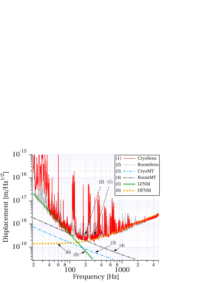
For comparison, Fig. 1 presents both the displacement sensitivity curve measured with the front CLIO mirrors cooled to 17 K and 18 K (cryogenic sensitivity; CryoSens) as well as the curve without cooled mirrors (room temperature sensitivity; RoomSens). CryoSens and RoomSens were measured on March 20, 2010 and November 5, 2008, respectively. The loop gain of the length control was measured immediately after each feedback signal measurement, and the response function of the coil-magnet actuators was calibrated for each experimental configuration. A sensitivity curve consists of frequency-dependent noise floors and multiple line noises. The noise floor level of CryoSens from 90 Hz to 240 Hz is below the noise floor level of RoomSens. By reducing this noise floor level, the detection range for GW signals from the binary coalescence of neutron stars in the optimal direction was improved from 150 kpc to 160 kpc. The noise floor at 165 Hz was reduced from to by cooling the front mirrors.
Discussion
The noise floors of the two sensitivities shown in Fig. 1 are very similar from 40 Hz to 90 Hz and from 400 Hz to 5 kHz, although additional line noises appeared in CryoSens. The line noise near 30 Hz results from the mechanical resonance of the cooled front mirror suspension systems. The line noise near 120 Hz and its higher-order harmonics are also caused by mechanical resonance in the suspension wires of the cooled front mirrors. The line noise at 60 Hz and its higher harmonics are similar to electric power line noise.
| Objects | Unit | Room temperature | Cryogenic | |
| Mirror temperature | K | |||
| Beam spot radius on front mirrors | mm | |||
| Beam spot radius on end mirrors | mm | |||
| Material properties of Sapphire | ||||
| Thermal expansion coefficient Touloukian et al. (1970); Taylor et al. (1996) | 1/K | |||
| Specific heat per unit volume Touloukian et al. (1970) | J/K/m3 | |||
| Thermal conductivity Touloukian et al. (1970) | W/m/K | |||
| Poisson’s ratio111We found various values for the Poisson’s ratio of sapphire between 0.23 and 0.30. We used the averaged value. | ||||
| Young’s modulus Yamamoto et al. (2006) | Pa | |||
| Mechanical loss Uchiyama et al. (1999) | ||||
| Mechanical loss in coating films Yamamoto et al. (2006) | ||||
| Thickness of coating films | m |
Figure 1 also shows the mirror thermal noise estimates corresponding to each sensitivity measurement (CryoMT and RoomMT), with the fitted lines for the noise floor in low-frequency region (the low-frequency noise model; LFNM) and high-frequency region (the high-frequency noise model; HFNM).
The parameters for the thermal noise calculation are summarized in Table 1. We did not perform any fits to the parameters. The RoomMT was calculated to be . Because the mirror thermal noise is larger with a smaller laser beam, the thermal noise of the front mirror is approximately twice as large as the thermal noise of the end mirror in the RoomMT. The CryoMT was greatly reduced to by the decrease in the thermal fluctuation of the cooled front mirrors. If all CLIO mirrors are cooled to 20 K, the mirror thermal noise near 100 Hz should be reduced to .
The LFNM was estimated from the noise floor of CryoSens between 40 Hz and 70 Hz and the noise floor of RoomSens between 20 Hz and 70 Hz, with a value of . A discussion of the origin of the LFNM is outside the scope of the current work. The HFNM was estimated from the noise floors of both sensitivity curves above 400 Hz by assuming a simple pole frequency dependence Saulson (1994). The HFNM consists of photocurrent shot noise and laser intensity noise at a frequency of 15.8 MHz and was estimated to have a value of ; the HFNM depends on the length and Finesse of the 100-m FP cavity. Cavity pole frequencies of 262 Hz and 246 Hz were obtained for the measurements of CryoSens and RoomSens, respectively. The systematic error in the noise floor amplitude due to the discrepancy in the cavity pole frequencies was less than 2% at frequency below 200 Hz.
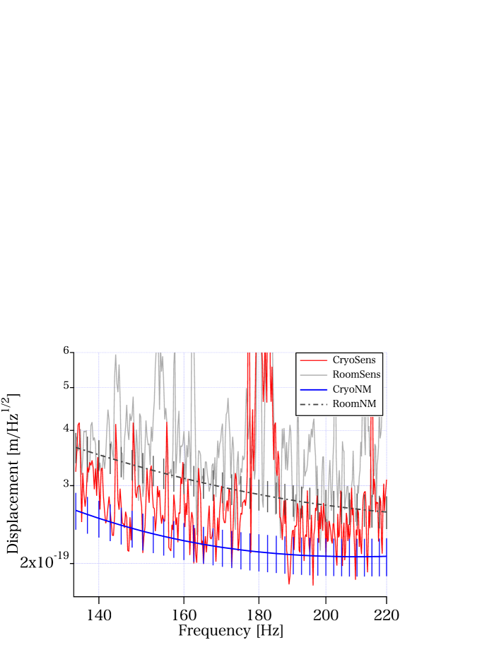
Figure 2 compares CryoSens, RoomSens, the cryogenic noise model (CryoNM) and the room-temperature noise model (RoomNM). CryoNM is the quadrature sum of the LFNM, the HFNM and CryoMT. RoomNM is the quadrature sum of the LFNM, the HFNM and RoomMT. Error bars are shown for both CryoNM and RoomNM, representing the quadrature sum of the calibration error and the noise estimation error. We estimated a 2.5% systematic error for the calibration, a 5% estimation error for CryoMT and RoomMT and a 10% statistical error for LFNM and HFNM. The noise estimation error is the quadrature sum of the error in the mirror thermal noise estimate (CryoMT or RoomMT) and the errors in LFNM and HFNM.
The noise floor of RoomSens agrees with RoomNM. The noise floor of CryoSens is below RoomNM and agrees instead with CryoNM. The difference between CryoNM and RoomNM is solely based on the mirror thermal noise estimate. Thus, we conclude that the sensitivity limitation due to thermal noise in the mirror at room temperature was improved by the noise reduction because of the decreased thermal fluctuation in the cooled front mirrors. This observation is the first demonstration that mirrors display less thermal fluctuation at cryogenic temperatures than at room temperature.
Conclusion
The thermal fluctuation of mirror surfaces represents the fundamental limitation on experiments that require high-precision measurements, such as experiments using a frequency-stabilized laser and GW detection using a laser interferometer. The cryogenic mirror technique uses a low-mechanical-loss mirror at a low temperature to reduce such fluctuations. Our demonstration using an actual GW detector directly proves that the cryogenic mirror technique effectively improves the sensitivity of the GW detector. This cryogenic mirror technique will be used in advanced GW detectors, such as KAGRA formerly called the Large-Scale Cryogenic Gravitational Wave Telescope Kuroda et al. (2010), on which construction began in the middle of 2010 in Japan, and the Einstein Telescope project in Europe Punturo et al. (2010). The mirror thermal noise of KAGRA near 100 Hz, which limits the sensitivity to at 299 K, will be reduced to at 20 K due to the cryogenic mirror technique. The KAGRA sensitivity will make it possible to detect a GW signal from the binary coalescence of neutron stars in the optimal direction up to 250 Mpc with a signal-to-noise ratio of 10 and the event rate is expected to be approximately 6 events per year Kuroda et al. (2010). We believe that our achievement represents a breakthrough in the study of thermal fluctuations, laser frequency stabilization and GW detection.
Acknowledgements.
We wish to thank our CLIO, TAMA and KAGRA collaborators, the Kamioka Observatory, Institute for Cosmic Ray Research, the University of Tokyo and Dr. Hiroaki Yamamoto of the LIGO laboratory for his advice on the manuscript. This work was supported in part by a Grant-in-Aid for Scientific Research on Priority Areas (No. 415) from the Ministry of Education, Culture, Sports, Science and Technology (MEXT). This work was also supported in part by a Grant-in-Aid for Scientific Research (A, No. 18204021) by the Japan Society for the Promotion of Science (JSPS).References
- Brown (1828) R. Brown, Phil. Mag. 4, 161 (1828).
- Numata et al. (2004) K. Numata, A. Kemery, and J. Camp, Phys. Rev. Lett 93, 250602 (2004).
- Saulson (1990) P. R. Saulson, Phys. Rev. D 42, 2437 (1990).
- Abramovici et al. (1992) A. Abramovici et al., Science 256, 325 (1992).
- Bradaschia et al. (1990) C. Bradaschia et al., Nucl. Instrum. Methods Phys. Sect A 289, 518 (1990).
- Callen and Welton (1951) H. B. Callen and T. A. Welton, Phys. Rev. 83, 34 (1951).
- Uchiyama et al. (1998) T. Uchiyama et al., Phys. Lett. A 242, 211 (1998).
- Uchiyama et al. (1999) T. Uchiyama et al., Phys. Lett. A 261, 5 (1999).
- Uchiyama et al. (2000) T. Uchiyama et al., Phys. Lett. A 273, 310 (2000).
- Yamamoto et al. (2006) K. Yamamoto et al., Phys. Rev. D 74, 022002 (2006).
- Tomaru et al. (2002a) T. Tomaru et al., Phys. Lett. A 301, 215 (2002a).
- Tomaru et al. (2001) T. Tomaru et al., Phys. Lett. A 283, 80 (2001).
- Miyoki et al. (2001) S. Miyoki et al., Cryogenics 41, 415 (2001).
- Ohashi et al. (2003) M. Ohashi et al., Class. Quantum Grav. 20, S599 (2003).
- Tomaru et al. (2002b) T. Tomaru et al., Class. Quantum Grav. 19, 2045 (2002b).
- Agatsuma et al. (2010) K. Agatsuma et al., Class. Quantum Grav. 27, 084022 (2010).
- Yamamoto et al. (2008) K. Yamamoto et al., J. Phys.: Conf. Ser. 122, 012002 (2008).
- Uchiyama et al. (2006) T. Uchiyama et al., J. Phys.: Conf. Ser. 32, 259 (2006).
- Ikushima et al. (2008) Y. Ikushima et al., Cryogenics 48, 406 (2008).
- Braginsky et al. (1999) V. B. Braginsky, M. L. Gorodetsky, and S. P. Vyatchanin, Phys. Lett. A 264, 1 (1999).
- Cerdonio et al. (2001) M. Cerdonio, L. Conti, A. Heidmann, and M. Pinard, Phys. Rev. D 63, 082003 (2001).
- Black et al. (2004) E. D. Black, A. Villar, and K. G. Libbrecht, Phys. Rev. Lett. 93, 241101 (2004).
- Nakagawa et al. (2002) N. Nakagawa, A. M. Gretarsson, E. K. Gustafson, and M. M. Fejer, Phys. Rev. D 65, 102001 (2002).
- Touloukian et al. (1970) Y. S. Touloukian, R. K. Kirby, E. R. Taylor, and T. Y. R. Lee, Thermophysical Properties of Matter - the TPRC Data Series (IFI/Plenum, New York, 1970).
- Taylor et al. (1996) C. T. Taylor, M. Notcutt, E. K. Wong, A. G. Mann, and D. G. Blair, Optics Communications 131, 311 (1996).
- Saulson (1994) P. R. Saulson, Fundamentals of Interferometric Gravitational Wave Detectors (World Scientific, Singapore, 1994).
- Kuroda et al. (2010) K. Kuroda et al., Class. Quantum Grav. 27, 084004 (2010).
- Punturo et al. (2010) M. Punturo et al., Class. Quantum Grav. 27, 084007 (2010).