Role of disclinations in determining the morphology of deformable fluid interfaces
Abstract
We study the equilibrium shapes of vesicles, with an in-plane nematic order, using a Monte-Carlo scheme and show that highly curved shapes, like tubes and discs, with a striking similarity to the structures engendered by certain curvature sensing peripheral membrane proteins, can be spontaneously generated by anisotropic directional curvature with nematic disclinations playing and important role. We show that the coupling between nematic order and local curvature could lead to like defects moving towards each other and unlike defects moving away, in turn leading to tube formation. Thermally induced defect pair production lead to branched tubular structures. It is also shown that helical arrangement of the membrane tubes, with nematic field spiraling around it, is a dominant soft mode of the system.
pacs:
PACS-87.16.D-, Membranes, bilayers and vesicles. PACS-05.40.-a Fluctuation phenomena, random processes, noise and Brownian motion. PACS-05.70.Np Interfaces and surface thermodynamicsFluid interfaces with an inplane orientational order can sustain amazingly complex morphologies. Apart from the interesting physics that it can offer, in terms of disclination dynamics on deformable surfaces, study of such interfaces are also contribute to understanding morphologies of cellular organelles.
The organelles of a biological cell have membranes with highly curved edges and tubes, as seen in the Endoplasmic reticulum, the Golgi and the inner membrane of mitochondria. Tubulation has also been observed, in vitro, in self assembled systems of pure lipids Markowitz:1991p3276 . It has been shown that, macromolecules, which constitutes and decorates the membrane surface, strongly influence the morphology of membranes. For instance proteins from the dynamin superfamily are known to pull out membrane tubes while oligomerizing themselves into a helical coat along the tubePraefcke:2004p3309 . The BAR domain containing proteins in general can induce a wide spectrum of membrane shapes ranging from protrusions to invaginations depending on the geometry and interaction strength of the BAR domain Zimmerberg:2006p510 ; Voeltz:2007p1399 ; Shibata:2009p643 .
The standard Helfrich modelHelfrich:1973p693 for membranes, based on mean curvature energy, cannot explain the stability of such highly curved structures. Existence of anisotropic bending energy will be the minimal requirement to explain the stability of tubular shapes, which could arise from an in-plane orientational field on the membrane Fournier:1996p488 ; Fournier:1998p2999 . Planar orientational order could be intrinsic to the membrane KraljIglic:2006p3974 , due to the structural properties of its constituents, or could arise as a result of membrane interactions with external agents Zimmerberg:2006p510 ; Voeltz:2007p1399 ; Shibata:2009p643 . Lipid molecules tilted with respect to the layer normal, as seen in the Smith:1988p3535 and Tardieu:1973p711 phases, is a well known case of intrinsic in-plane orientational order. Anisotropic peripheral proteins (curvactants), inducing membrane deformations Yin:2009p255 either by scaffolding or by insertion of their amphipathic helices into the membrane Zimmerberg:2006p510 , are examples for extrinsic sources of orientational order. In general the order can be represented by a -atic surface field, invariant under rotations by . Equilibrium shapes of a surface with -atic in plane order, have been investigated earlier Park:1992p946 ; MacKintosh:1991p685 . Mean field phenomenological models of orientation order on membrane surface, in the context of lipid tilt and chirality, have predicted the stability of tubular membranes and helical ribbonsHelfrich:1988p3004 ; Nelson:1992p9 ; Selinger:1993p108 ; Schnur:1993p1277 . More recently, a mesoscopic particle model was used to show that presence of BAR domains on membrane surfaces can lead to tubulation and vesiculation Ayton:2007p3485 ; Ayton:2009p3487 .
The coupling of curvature to orientational order leads to interesting defect dynamics and thermally excited shapes. Thus in addition to its biological relevance, membranes with in plane order also provides a unique medium to study disclination dynamics on deformable surfaces. So far such studies have been carried out only on surfaces with prescribed curvature Shin:2008p174 . Apart from the interesting physics that it can generate these investigations may also provide new routes to new functional materialsNelson:2002p335 .
In this paper we use the Monte Carlo model developed by us Ramakrishnan:2010p1249 ; supp to explore the spectrum of vesicle shapes engendered by an in-plane nematic field . The technique developed by us enables one to go beyond the mean field regime and also to explore the full nonlinear regime. We scale all energies by . A moderate mean curvature stiffness is chosen to enable study of thermally induced shape fluctuations. Higher values of are chosen to study equilibrium shapes in the absence of thermal fluctuations. We choose the directional curvature moduli, along and perpendicular to the orientational field, as and respectively. The results with is qualitatively same and is not discussed separately. We vary the spontaneous curvature along the in-plane field , to explore different shapes. The in-plane nematic field, distributed uniformly over the entire surface, is constrained to be in the ordered phase by setting the Lebwohl Lasher coupling constant Lebwohl:1972p426 . For this values of the coupling constant, with , the nematic field orients itself on a tetrahedron with four disclinations, as predicted in Park:1992p946 . We will first investigate the effect of the directional spontaneous curvature on the equilibrium membrane conformations when the value is high so that thermal undulations can be neglected.
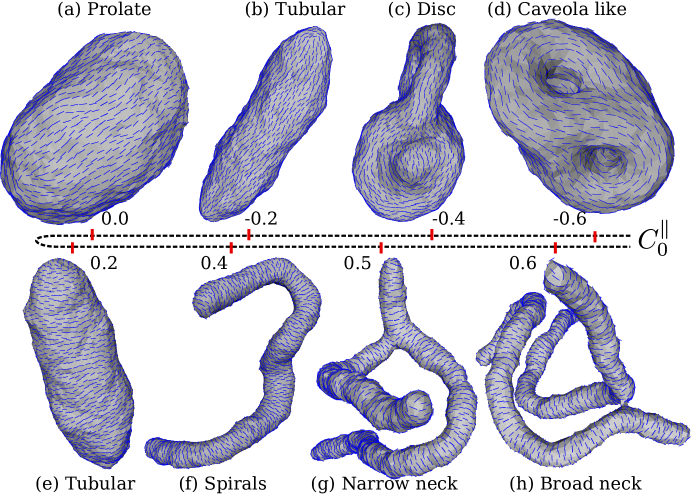
At high thermal undulation does not change the shapes significantly and the shapes obtained from the equilibrium simulations will be the same as that from a mean field calculation. It is known that dynamic triangulation Monte Carlo (DTMC) models, based on Helfrich Hamiltonian Helfrich:1973p693 , do reproduce the mean field phase diagram of vesicles Gompper:1994p205 . Here we determine the equilibrium shapes of decorated vesicles with an in-plane orientational order, also taking thermal fluctuations into account . As can be seen from Fig.1, we see tubular and disc like shapes emerging, even when there are no constraints on the area to volume ratio of the vesicle. Directional spontaneous curvature and interaction between the disclinations are two important factors that determine the shape of these decorated vesicles. Since the membrane is self avoiding the constraint imposed by the fixed topology also plays a role.
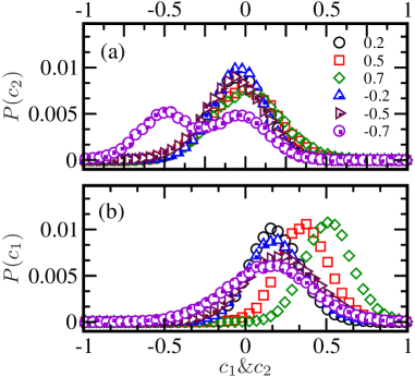
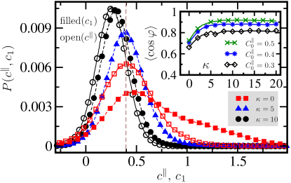
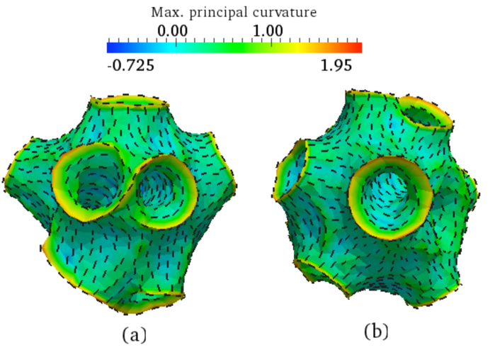
Four curvatures can be identified, the curvatures along the principal directions with and the directional curvatures, , along and perpendicular to . Fig.2 shows the distribution , of , on a vesicle, for different values when . It is clear from Fig.2(a & b) that for the distributions have a single peak, with , peaked close to, but less than, the value of , while is peaked at zero. The resultant value of the principal curvature arising from the competition between the resistance to bending imposed by and the directional spontaneous curvature set by , is shown in Fig.3. When decreases the peak position of moves toward that of and then to a value higher than for . Note that for there are no competing elastic forces and the desired directional curvature can be achieved by setting at an angle with respect to the direction of . For a tube, a non zero value of implies a configuration with nematic spiraling around the tube. The angle is shown as inset in Fig. 3. As expected this angle is a decreasing function of the bending modulus and saturates to zero for large bending rigidity.
Negative spontaneous directional curvature () induces tubes to form into the vesicle. However, restrictions imposed by the membrane self avoidance and topology prevent a complete inversion of the membrane through inward tubulation. This leads to a bimodal distribution of , with a peak at in addition to the expected peak at (see Fig.2 a). This bimodal peak arises due to presence of inward tubes (with most of the vertices with ) and an outward curved surface (with most vertices having ).
Another important factor that determines the shape of a vesicle is the positioning of disclinations. We know that, for a nematic field on a closed surface with spherical topology, the total disclination strength should be 2. There is no such topological restriction on the number of defects themselves and thermal fluctuation could excite oppositely charged defect pairs.
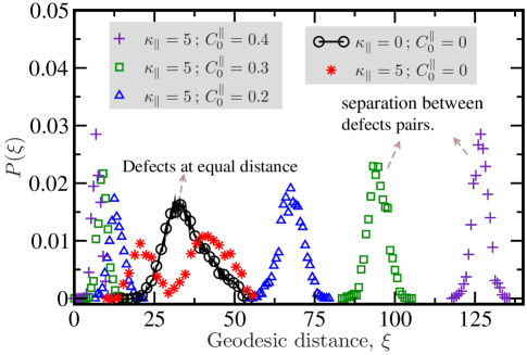
In the absence of any stiffness-orientation coupling, the energy of a pair of defects, on a surface of spherical topology, decreases logarithmically with separation Lubensky:1992p531 and is repulsive when their charges are of the same sign Park:1992p946 . We therefore expect, at low temperatures, to see four disclinations at equal distance from each other. In Fig.4 this is evidenced in the single peak in the measured distribution of geodesic distances () between the defects. Directional bending stiffness ( ) alters this distribution considerably, since curvature influences the interaction between defects Bowick:2009p955 ; Vitelli:2006p1462 . We see that two of the defects move towards each other to form pairs as the vesicle deforms into a tube, resulting in a peak in the distribution at short separation as shown in Fig.4. This peak moves towards the left as increases. The pairs, which now has a total strength of , moves away from each other, resulting in a second peak in . This peak position moves to the right as is increased. We thus observe nontrivial changes in the interaction between disclinations due to the geometry of the embedding surface. For , there is a proliferation of defects as the inward tubes are formed. The inner side of the tubes are decorated with along the circumference with the tip hosting a pair of defects. There is a sudden change in the orientation of just out side the rim of the tube(see Fig.5). The rim itself is thus a line of discontinuity. There are two types of rims, closed ones with four defects outside and paired open rims ending in two defects.
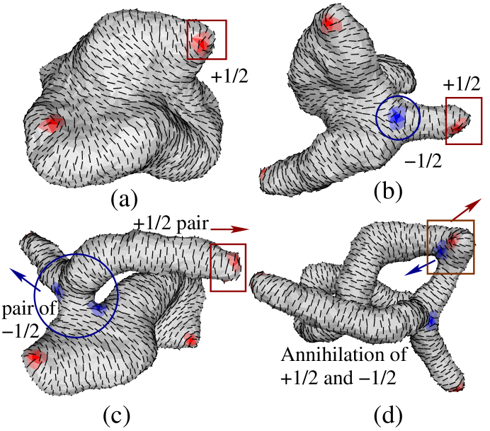
A variety of thermally excited shapes are also seen. The lowest energy thermal modes among the tubes are the spirals, which are always present unless one is at a very low temperature (see figure 1f). If we raise the temperature or decrease the value of , the tubes develop branches. More branches are produced as the temperature is increased, with every branch having a pair of defects at the intersection and a pair of defects at the tip supp . Fig.6 shows the sequence of snap shots that depict the transformation of a sphere with an initial random orientation of the nematic to a tube, when quenched from to , while keeping and footnote . The nematic instantly orients on the sphere resulting in four defects at equal distance from each other. The membrane then begins to deform, through formation of protrusions at the defect cores (Fig.6(a)), since positive defects favor positively curved regionsBowick:2009p955 and to satisfy the curvature set by and . These membrane protrusions are accompanied by production of oppositely charged half defect pairs(Fig.6(b)). The negative defects move to the negatively curved intersections and the positive defects move to the positively curved tip of the protrusions. When the tip of a protrusion has two defects, and its neck two , that branch is stabilized and grows by moving the positive and negative defect pairs away from each other(Fig.6(c)). Isolated and defects annihilate(Fig.6(d)). In general two types of branched structures are observed, as we increase the directional spontaneous curvature, (a) Broad necked, see Fig.1(g) and (b) Narrow necked, see Fig.1(h) .
To analyze the origin of helicity, we neglect the end cap effects of the tube and parameterize it as a canal surface. The total elastic energy, per unit length, is then supp . Here is the radius of the tube and . The energy depends only on the curvature of its spine curve , and not on the torsion, hence for there is a degeneracy of spiral configurations corresponding to different torsions. One can easily see that the energy is at its minimum when supp . For a tube of length , parametrizing the spiral deformations by the extension of the tube along the helical axis , we can estimate the entropy to be of the order and for small values the entropy term will dominate the free energy resulting in helical configurations.
Before we conclude, let us look at how does the model parameters like the spontaneous curvature and the density of nematic inclusions compare with experiments. For , the circumference of the tube is about 4 tether lengths. Comparing this with the radius of the lipid tubes obtained in experiments Sweitzer:1998p3632 we get the length of the tether to be nm. The value of in real units is thus , which is not far from the suggested value of dynamin intrinsic curvature. Experiments see the dynamin rings surrounding the tubes to be made of about 20 units with a pitch of about nm. This will translate to about 5 dynamin molecules per vertex in the simulations.
In conclusion, we have shown that in-plane nematic order couple to curvature, on a deformable surface, can lead to non-trivial shapes of vesicles. The deformability of the surface lead to generation of point defects and line singularities,which in turn leads to production of tubes and branches.
References
- (1) M. Markowitz and A. Singh, Langmuir 7, 16 (1991).
- (2) G. J. K. Praefcke and H. T. McMahon, Nat. Rev. Mol. Cell Biol. 5, 133 (2004).
- (3) J. Zimmerberg and M. M. Kozlov, Nat. Rev. Mol. Cell Biol. 7, 9 (2006).
- (4) G. K. Voeltz and W. A. Prinz, Nat. Rev. Mol. Cell Biol. 8, 258 (2007).
- (5) Y. Shibata, J. Hu, M. M. Kozlov, and T. A. Rapoport, Annu. Rev. Cell Dev. Biol. 25, 329 (2009).
- (6) W. Helfrich, Z. Naturforsch. C 28, 693 (1973).
- (7) J. B. Fournier, Phys. Rev. Lett. 76, 4436 (1996).
- (8) J.-B. Fournier and P. Galatola, Brazilian J. Phys. 28, 329 (1998).
- (9) V. Kralj-Iglič et al., J. Stat. Phys. 125, 727 (2006).
- (10) G. S. Smith, E. B. Sirota, C. R. Safinya, and N. A. Clark, Phys. Rev. Lett. 60, 813 (1988).
- (11) A. Tardieu, V. Luzzati, and F. C. Reman, J. Mol. Bio. 75, 711 (1973).
- (12) Y. Yin, A. Arkhipov, and K. Schulten, Structure 17, 882 (2009).
- (13) J. Park, T. C. Lubensky, and F. C. Mackintosh, Europhys. Lett. 20, 279 (1992).
- (14) F. C. MacKintosh and T. C. Lubensky, Phys. Rev. Lett. 67, 1169 (1991).
- (15) W. Helfrich and J. Prost, Phys. Rev. A 38, 3065 (1988).
- (16) P. Nelson and T. Powers, Phys. Rev. Lett. 69, 3409 (1992).
- (17) J. V. Selinger and J. M. Schnur, Phys. Rev. Lett. 71, 4091 (1993).
- (18) J. M. Schnur, Science 262, 1669 (1993).
- (19) G. S. Ayton, P. D. Blood, and G. A. Voth, Biophysical Journal 92, 3595 (2007).
- (20) G. S. Ayton et al., Biophys. J. 97, 1616 (2009).
- (21) H. Shin, M. Bowick, and X. Xing, Phys. Rev. Lett. 101, 037802 (2008).
- (22) D. R. Nelson, Nano Lett. 2, 1125 (2002).
- (23) N. Ramakrishnan, P. B. S. Kumar, and J. H. Ipsen, Phys. Rev. E 81, 41922 (2010).
- (24) See supplementary materials at http://www.rsc.org/suppdata/sm/c2/c2sm07384f/c2sm07384f.pdf
- (25) P. A. Lebwohl and G. Lasher, Phys. Rev. A 6, 426 (1972).
- (26) G. Gompper and D. M. Kroll, Phys. Rev. Lett. 73, 2139 (1994).
- (27) T. C. Lubensky and J. Prost, J. Phys. II France 2, 371 (1992).
- (28) M. Bowick and L. Giomi, Adv. Phys. 58, 449 (2009).
- (29) V. Vitelli and D. R. Nelson, Phys. Rev. E 74, 21711 (2006).
- (30) Such a quench can be achieved by a change in temperature across the isotropic-nematic transition, wherein the mean bending modulus remains almost the same but a sharp change in the nematic stiffness.
- (31) S. M. Sweitzer and J. E. Hinshaw, Cell 93, 1021 (1998).