ProofFlow: Flow Diagrams for Proofs
Abstract
We present a light formalism for proofs that encodes their inferential structure, along with a system that transforms these representations into flow-chart diagrams. Such diagrams should improve the comprehensibility of proofs. We discuss language syntax, diagram semantics, and our goal of building a repository of diagrammatic representations of proofs from canonical mathematical literature. The repository will be available online in the form of a wiki at proofflow.org, where the flow chart drawing software will be deployable through the wiki editor. We also consider the possibility of a semantic tagging of the assertions in a proof, to permit data mining.
Keywords:
proofs, diagrammatic representation, flow charts, repositories of formalized mathematics, web presentation of mathematics, data mining1 Introduction
In the spectrum of formality, from completely informal prose proofs intended for human readers, to proof scripts checkable by automated theorem provers or proof assistants, we propose a light level of formalism which we shall refer to as the flow level, in comparison to flow charts. At this level we formally register which assertions are said to follow from which others, thus capturing the inferential structure of the proof, without formalizing the assertions themselves, or demanding that the inferences be justifiable in any particular proof system.
Proofs written in English muster their declarative statements and assumptions into an argument using a standard battery of words and phrases, such as so, therefore, by, then, hence, using, it follows that, etc. These words provide some indication as to which assertions are being used when others are inferred, but the information is usually incomplete.
For example, six assertions might so far have been made in an informal proof, at which point the author might write, “Therefore .” The author will have it in mind that follows from , , and , say, and will expect the reader to see this as well, but will not make this information explicit. The word ‘therefore’ really just says, “At this point you have enough to infer . Figure out how.”
At the flow level of representation of proofs, we make this information complete and explicit. In the language of formal natural deduction systems, a claim that an assertion follows from assertions is called a judgment, and may be written . In a flow-level formalization then, while the formalizer need not add any justification for any judgment over and above what is already present in the proof, the judgments themselves are to be made explicit. We show in Section 3 how this is done in the ProofFlow language.
The primary purpose of formalizing a proof in the ProofFlow system is to improve its comprehensibility. We provide software that will take a proof written in the ProofFlow language and produce a flow chart representation of it. The system is deployed through a wiki at proofflow.org.
Many argument mapping systems exist, and a long list can be found at [4]. Most of these, however, seem to cater to the needs of real-world arguments, while none seem to address the special demands of diagraming mathematical proof structure. Moreover, it is suggested in [2] that more sophisticated layout is needed in such systems, and new layout techniques are applied. The ProofFlow system could benefit from similar techniques.
ProofFlow should aid comprehension of proofs in at least two ways: (1) Readers are not left wondering which prior assertions should be used in inferring a given one. (2) The diagram gives an overview of the proof. The reader can see at a glance how all the parts of the proof fit together, including how many times and where in the proof each assertion is used. In particular this should counteract the sensation often experienced on finishing a proof, that one has confirmed each separate inference well enough, but has lost the forest for the trees.
Though the feature has not been implemented yet, in a future version of the system we plan to allow users to expand and collapse parts of proofs which authors have prepared as “further clarifications”. Thus, a proof will be presented at an initial level of discourse, with some inferential gaps being perhaps quite large, while further information as to how these gaps are to be filled in may be held in reserve. If the user requested it, this information could be depicted by adding new nodes and directed edges to the diagram. Expansion and collapse techniques were implemented in [2]. In [1] separation constraint techniques are discussed which allow smooth alteration of graphs, so that viewers’ mental models are not disturbed.
2 ProofFlow Diagrams
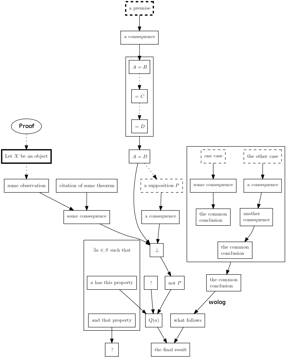
In a flow diagram for a proof, we put statements into boxes, and draw arrows connecting the boxes both in order to show the inferential structure of the proof, and in order to direct the reader through the proof from start to finish. See for example Fig. 1. (The input for Fig. 1 is given in Fig. 2, and will be explained in Section 3.)
I01 {s Let $X$ be an object}
A02 {s some observation}
A03 {s some consequence}
C04 ( citation of some theorem )
E05 [ {s $\exists a \in S$ such that}
      {s $a$ has this property}
      {s and that property} ]
A06 {s a consequence}
A07 {s $A = B$}
A08 {s $ = C$}
A09 {s $ = D$}
A10 {s $A = D$}
A11 {s a supposition $P$}
A12 {s a consequence}
P13 {s a premise}
A14 {s not $P$}
A15 {s $Q(a)$}
A16 {s one case}
A17 {s some consequence}
A18 {l {s the common} {s conclusion} }
A19 {s the other case}
A20 {s a consequence}
A21 {l {s another} {s consequence} }
A22 {l {s the common} {s conclusion} }
A23 {l {s the common} {s conclusion} }
A24 {s what follows}
A25 {s wolog}
A26 {s the final result}

link (
    I01 go A02. So A03 by C04. Now E05. And A06 by P13.
    Now Proof
        A07 by A06 go A08 go A09
    end.
    So A10. Next suppose A11.
    Then A12, then falsum, by A10, A03.
    So A14. Then A15 by ?, E05_1.
    Now cases,
        Case A19. Then A20, so A21, so A22.
        Now Case A16. Then A17, so A18.
    end.
    So A23. Then A24 using A25. So A26 by A15.
    But ? by E05_2.
)
Beyond this we use a few additional graphical conventions, but overall the diagram semantics are quite simple. The set of graphemes, or the graphical vocabulary that we use, is very small: The boundaries of boxes may be solid or dashed, plain or bold; the arrows between boxes may be solid or dashed. We explain the meanings of these different styles in the subsections below.
We use the GraphViz111http://graphviz.org program dot to lay out and draw our diagrams, since they are really directed graphs. Accordingly, we may discuss our diagrams, which we refer to as ProofFlow diagrams, not just in terms of boxes and arrows, but also in terms of nodes (or vertices) and edges.
2.1 Nodes for Assertions, Object Introductions, Premises, and Assumptions
Apart from a few exceptions (to be discussed in Sections 2.4, 2.5 and 2.6), the text appearing on each node in a ProofFlow diagram must give either (1) a mathematical assertion, (2) the introduction of a mathematical object, (3) a premise from the statement of the theorem being proved, or (4) an assumption, to be discharged somewhere in the proof. For each of these possibilities we provide a special kind of node, whose boundary is drawn in a special way.
Assertions are the declarative statements that make up most of a proof. These appear on nodes with solid (i.e. not dashed), plain (i.e. not bold) boundary, called assertion nodes, or A-nodes.
Statements defining or introducing objects into a proof will appear on nodes with a solid, bold boundary, called introduction nodes, or I-nodes. The bold boundary makes I-nodes easy to find, in case the viewer wants a reminder of the definition of an object. Also we feel that since assertions have a truth value whereas definitions do not, it is only proper that assertions and introductions take place in nodes that look different.
Here we introduce some technical terminology: Typically a theorem statement will involve assumptions, and we refer to these as premises, whereas any additional assumptions employed during a proof, such as for proof by cases or proof by contradiction, will be called simply assumptions.
In ProofFlow diagrams we write all premises and assumptions inside boxes with dashed boundaries. In addition, the boundary is bold for a premise, and plain for an assumption. This makes premises and assumptions easily distinguishable from one another, so that viewers will not accidentally expect premises to be discharged. We hope that the convention is also intuitive: The dashed lines represent the contingent nature of all premises and assumptions, whereas the bold lines for premises represent their essential role in a theorem statement, as opposed to the transient nature of assumptions which will be discharged by the end of the proof.
There is a special premise node, or P-node, for premises. There is no special node for assumptions. Instead, they are made from A-nodes, and get their dashed boundary from the key word suppose, as explained in Section 3.
2.2 Deduction
In order to represent a judgment we draw solid arrows, called deduction arrows, from the to . Deduction arrows are visible in Fig. 1.
2.3 Scoping and Flow
When we read a prose proof we always know what objects have been introduced since they are defined before they are used, and we always know what assumptions are in force since they are stated before they are used. Questions as to where in a proof objects or assumptions are in effect are questions of scope.
In a flow diagram for a proof we stand to find ourselves confused on matters of scope, since we throw away much of the linear order of the prose, and we are liable to view the nodes in the graph in the wrong order.
In order to avoid this problem we employ what we call flow arrows in a ProofFlow diagram. A flow arrow from node to node is drawn dashed rather than solid, and rather than saying that is used in deducing it simply says that after you have considered the author of the proof wants you to consider next. See Fig. 1 for examples.
So that the proof has a starting point, we automatically include a single oval-shaped node reading “Proof,” which points with a flow arrow toward the first node declared in the proof. (See Section 3 on node declarations.)
In this way we ensure that the viewer is directed through a ProofFlow diagram in an appropriate order, so that he or she will not encounter a statement about an object without already having seen the definition of , and so that it will be clear which assumptions are in force at any given point.
While in completely formal proofs, such as Fitch-style proofs, both the beginning and the end of the scope of any assumption is made clear by means of clearly delimited subproofs, in general we get away without taking such care in prose proofs. The linear order of the discussion seems to suffice. Flow arrows therefore should also suffice in ProofFlow diagrams. If not, formalizers may choose to put certain deduction chains into boxed subproofs. (See Section 2.7.)
Formalizers and viewers of ProofFlow diagrams should follow these rules regarding the use of flow and deduction arrows:
-
1.
There should not be both a flow and a deduction arrow going from a node to a node ; in this case only the deduction arrow should be used; the viewer will understand that it is to be followed.
-
2.
A single node might have a flow arrow to a node and deduction arrows to one or more other nodes . In this case the viewer should follow the flow arrow; the deduction arrows will naturally come into consideration later in the proof.
-
3.
There should never be more than one flow arrow leaving a single node.
-
4.
In general, the viewer should never be left wondering where to go next.
2.4 Citation Nodes
When a theorem or lemma is cited in support of a claim, we put the name of the result in a special citation node, or C-node, and draw a deduction arrow from the C-node to the claim. The proofflow.org web site is still largely under construction, but when more infrastructure is in place then C-nodes will provide clickable links to the results that they name.
2.5 Question and Falsum Nodes
When the contradiction is reached in a proof by contradiction, this should be shown in a ProofFlow diagram by deducing an A-node displaying only the falsum symbol, . We provide a convenient way to generate such a node, which we discuss in Section 3.
A formalizer may be unsure about certain parts of a proof, and in this case question nodes should be used. A question node is an A-node displaying only a question mark, and again we provide a convenient way to generate such a node, to be discussed in Section 3.
Specifically, if the formalizer feels that a (possibly empty) set of nodes are used in inferring node , but that something more is also needed, though he or she is not sure what, then in addition to a deduction arrow from each to , there should also be a deduction arrow from a question node to .
On the other hand, if the formalizer does not know where an assertion is used in a proof, but feels that it should be used somewhere, then there should be a deduction arrow from to a question node. Care should be taken to maintain flow in this case; in particular, it may be necessary to draw a flow arrow leaving the question node. See Fig. 1 for demonstration of both uses of question nodes.
2.6 Existence and Introduction
In a highly formal proof, it is one thing to say that an object of a certain kind exists, and it is another thing to introduce such an object. These form two separate steps in the proof. In informal proofs, however, these steps usually occur simultaneously, with the existence being stated explicitly, and the introduction of such an object being implicit.
For example, the author of a proof in group theory might say that there exists a group homomorphism having certain properties, and in the next breath proceed to talk about . As the reader of the proof we understand that now refers to an arbitrary object of the kind just stated to exist.
In order to accurately model informal proofs, we too combine these steps in ProofFlow diagrams. After drawing a node that states the existence of an object, the formalizer may then proceed immediately to draw nodes that discuss such an object.
It is important however that later on in the proof we have a way to cite not just the existential statement itself, but also the individual statements of the properties of the existing object. For this reason we provide a special existence node, or E-node, with which to make the existence statement. (Its syntax is described in Section 3.)
Let us consider for example the following three steps from the proof of Theorem 90 in [5]:
-
1.
an integer such that .
-
2.
Define .
-
3.
.
In line 1 we state the existence of an integer with a certain property, in line 2 we then go on to use such an integer to construct a number , and in line 3 we assert an equation involving .
When we infer line 3, we rely on the fact that , not on the existence of such an integer . Therefore in a ProofFlow diagram we need to be able to draw an arrow not from a box around the existential statement, but from another box, around the statement that . E-nodes provide for this in ProofFlow diagrams. See example at bottom of Fig. 1.
2.7 Subproofs
Sometimes in an informal proof we make a claim, and then devote a special subproof to the support of this claim. Such a subproof will be depicted in a ProofFlow diagram by surrounding all the nodes of the subproof within a box.
Deduction and flow arrows may be drawn from the surrounding box of a subproof to other nodes in the diagram. The box is also “transparent” in that it is still possible to draw arrows connecting the nodes inside to nodes outside the subproof. It is not possible to draw a deduction arrow to a subproof, since a subproof is not the sort of thing which, in its entirety, is to be supported by a reason! A flow arrow can however be drawn to a subproof.
One particular type of subproof is proof by cases: We consider a series of assumptions in order, and show that under each assumption (without any of the others) we can reach one and the same conclusion . While we entertain the possibility of using special graphemes for proof by cases in the future, at present we simply depict each of the assumptions with a dashed boundary, as with any other assumption, and collect each of the deductions from to together inside a subproof box. See key words cases and case in Section 3 for further details.
2.8 Relation Chains
Relation chains are a common feature in informal proofs. These may be chains of equations, inequalities, subset relations, or other infix relations. Such displays might have the following form:
Since each relation in the chain represents a separate assertion which may need to be justified or may be used in later justifications, there should be a separate box around each relation, in a ProofFlow diagram.
Therefore we make the following graphical convention for relation chains: The first relation (e.g. ) should go in a node , and subsequent relations (e.g. , …, ) should be written, starting with the relation symbol, in nodes . Flow arrows should be used to link to , to , and so forth up to . See again Fig. 1 for an example.
2.9 Edge Labels
A label may be put along a deduction arrow in order to give some indication of the method of inference that is being used. At present we support only text, not graphical, edge labels.
Two important examples will be the labels “by induction,” and “wolog” or “without loss of generality”. Formally speaking, “wolog” is really a way of saying, “We’re going to do proof by cases, but we’re actually only going to discuss one of the cases, since all the others can be reduced to it.” In a ProofFlow diagram, the assumption introduced “without loss of generality” should be led to by an arrow labeled “wolog”.
3 The Language
The ProofFlow language is very simple. In an input file, the user first declares all nodes, giving them names and giving the text that should appear in them. The user then writes a paragraph called a proof script that links the nodes together by edges, labels edges if desired, makes nodes into assumptions as appropriate, and can put nodes into subproofs. See Fig. 2 for the input file that produced Fig. 1.
Each node in a ProofFlow diagram gets a name, which may use only capital and lowercase letters, and digits. The first character must be one of the capital letters in the set [ACEIP], and this indicates what type of node it is. We review the different types of node below.
Recommended practice is to simply number the nodes in order of their use in the proof, so that the name of each node consists of an initial letter indicating its type, followed by a numeral. For example: I00, A01, A02, A03, C04, E05, and so forth.
3.1 Text Objects
The text displayed on nodes is typeset using LaTeX. Since a node is a small rectangular box, we will often want the text to be laid out not as it would be on a page, but rather in short lines arranged in a left- center- or right-aligned column. The user may achieve this through standard LaTeX commands, but we also provide convenient shortcut syntax for this purpose.
Text is placed inside a text object, which is delimited by braces {} and which must begin either with a sequence of the letters [lcr] to indicate that a table environment with left- center- and right-aligned columns is desired, or else with the letter s to indicate that no such formatting is desired. Text objects may be nested to as great a depth as LaTeX will accept.
For example, the text object
     {l
         {s $K$ a number field,}
         {s $L$ its normalization.}
     }
produces two left-aligned lines of text:
3.2 Node Types
3.2.1 Assertion Nodes or A-nodes.
The name of an assertion node must begin with an A. To declare an assertion node the user simply types the name of the node, followed by a text object giving the text that should appear on the node. For example:
A01 {s $a \in K$}
3.2.2 Citation Nodes or C-nodes.
A citation node is used in order to cite a separate theorem or lemma. The name of a citation node must begin with a C. It takes a single argument given in parentheses (), which gives the name of the result being cited, and within the context of the wiki at proofflow.org will also provide a hyperlink to a page devoted to that result. (As of the time of this writing, the hyperlink feature is not yet implemented.) For example:
C02 ( Zahlbericht_Thm_148 )
3.2.3 Existence Nodes or E-nodes.
Recall from Section 2.6 that existence nodes achieve the special purpose of both stating the existence of an object or objects, and at the same time introducing those objects. An existence node must have a name beginning with an E. It takes a square-bracket-delimited sequence of text objects as its argument. For example:
  E03 [
    {s $\exists$ an integer $a \in \mathbb{Z}$ such that}
    {s $\psi(a) \neq 0$.}
  ]
In general, if are the text objects passed to an existence node named Ename, then should name a mathematical object and state its existence, while should state the properties of the object. In the above example, the two text objects
| : | an integer such that | |
|---|---|---|
| : |
follow this rule. In order to refer to the individual text objects later, they are automatically assigned the names Ename_0, Ename_1, …, Ename_. In our example, the assertion will appear in a boxed node that can be referenced as E03_1.
Note however that whereas each of the two text objects , in our example will have a box around it so that it can play a role in the proof, we cannot meanwhile cite the substatement of which says “.” This might be desirable, as a way of saying, “Here we are using the fact that is an integer.” While at present there is no way to do this in the ProofFlow syntax, we hope to provide this feature in the future.
3.2.4 Introduction Nodes or I-nodes.
An introduction node has a name beginning with I, and introduces new objects into the proof. It takes a single text object as argument. For example:
I04 {s Let $L$ be the normalization of $K$. }
3.2.5 Premise Nodes or P-nodes.
The name of a premise node begins with the letter P. It recalls one of the premises made in the statement of the theorem being proved. It takes a single text object as argument. For example:
P05 {s $N(a) = 1$}
3.3 The Linking Language
Once all nodes have been declared it is time to link them together into a proof. To achieve this the user writes a paragraph in the ProofFlow linking language, which we call a proof script, and passes it to the link function, as in Fig. 2. The language uses only the names of the declared nodes together with the following key words (words written on the same line are synonyms):
     so, then
     by
     go, next
     now, and, but
     suppose, case
     proof, cases
     end
     using
     ?
     falsum
White space is ignored, the key words are not case-sensitive, and the three punctuation symbols [;,.] are also ignored. Thus the paragraph may be organized into “sentences” if desired, although this is not necessary. See the example at the bottom of Fig. 2.
3.3.1 The Keywords.
by: Key word by introduces supporting reasons. Thus,
A0 by A1 A2 A3 ...
will cause deduction arrows to be drawn to node A0 from each of the nodes A1, A2, A3, ....
In general the head of the deduction arrows will be the most recent node named. Thus,
A0 by A1 by A2
will yield two deduction arrows: one from A1 to A0, and one from A2 to A1.
so, then: Key word so (and synonym then) introduces logical consequences. Thus,
A0 so A1 A2 A3 ...
will cause deduction arrows to be drawn from node A0 to nodes A1, A2, A3, ....
In general the tail of the deduction arrows will be the most recent node that has been deduced (not named as a supporting reason). Thus,
A0 by A1 so A2
will yield two deduction arrows: one from A1 to A0, and one from A0 to A2.
go, next: Key word go (and synonym next) introduces a flow arrow. Thus,
A0 go A1
draws a flow arrow from node A0 to node A1. As with so and then, the tail of the flow arrow will be the most recent node that has been deduced.
now, and, but: Key word now and its synonyms allow the user to introduce a node that is not connected to any of those already named. Thus, if we have just shown that node A0 implies node A1, say, and want to now start a separate chain of reasoning, in which node A2 will imply node A3, we may write
now A2 so A3
suppose: If the key word suppose is placed before a node A1 then node A1 will be taken as an assumption, and will be given a dashed boundary.
proof and end: The key word proof starts a subproof, and the key word end ends it. Everything inside the subproof will be drawn inside a box in the ProofFlow diagram. Syntactically, the entire subproof can be used precisely as any node name is used, except that a subproof cannot come after the so and then key words. (Thus, a subproof can be a reason, but cannot be a consequence.)
cases and case: The key word cases is meant to initiate a special kind of subproof, namely, a proof by cases. Within such a subproof the key word case indicates the start of a new case. The entire subproof is terminated by the key word end.
In future versions of the system we may use more specialized graphical conventions to represent proof by cases, but for now cases is just a synonym for proof, and case is just a synonym for suppose. The user should not forget to put now (or a synonym) before each case after the first.
using: After a deduction arrow is introduced by either the so or by key words or their synonyms, the key word using will put a label on the arrow. The label for the arrow should have been declared in an assertion node, using plain text in the text object for the node, since the text will not be typeset by LaTeX.
falsum and ?: Anywhere in the proof script where a node name may appear, the user may write falsum or ?, which will automatically generate a node featuring only a typeset ‘’ or ‘?’, respectively. As was discussed in Section 2.5, the former is for use in proof by contradiction, and the latter in case the author of the proof script is unsure how an inference is to be made.
If it is clear, for example, that A1 and A2 were used in inferring A0, but the formalizer thinks that something more still is needed, then a question node should be used, as in:
A0 by A1 A2 ?
On the other hand, if an assertion A3 has been made in the proof, but the formalizer does not see where A3 is used, then a question node should be placed as the consequence of A3, as in:
A3 so ?
3.3.2 Putting it Together.
A complete proof script might read something like the example at the bottom of Fig. 2.
4 Conclusions and Outlook
4.1 Building a Catalog of Proofs
The ProofFlow system is available in a wiki at proofflow.org, where we aim to build a catalog of proofs displayed in flow diagrams. The site is built on the Mediawiki wiki engine,222http://www.mediawiki.org/wiki/MediaWiki and the ProofFlow software is deployed via an extension to the wiki editor: ProofFlow input is to be placed inside a pair of <proofflow>, </proofflow> tags.
It is hoped that the ProofFlow website will be used as an aid in exploring dense mathematical literature, in particular classic or canonical works. We have begun with Hilbert’s Zahlbericht [5].
Ultimately we hope that a large corpus of proofs from classic mathematical literature will be formalized, and that the web site will facilitate studies in the history of ideas in proofs.
4.2 Data Mining
Besides facilitating aids to the comprehensibility of a proof such as flow diagrams, the flow level of formalization also provides interesting opportunities for data mining.
By formalizing the inferential structure of a proof as it is presented to human readers, we provide ourselves with a data set in which we can hope to discover patterns of reasoning at a tactical level on which mathematicians are accustomed to thinking.
We might hope that mining for patterns at this level could reveal generalizations about writing proofs comparable to those that are often made about a tactical but enormously complex game like chess, where advice takes the form of statements such as “control the center,” “activate your minor pieces early,” etc. The prospects might be improved here if we were to concentrate on one area of mathematics at a time, say, algebraic number theory. Perhaps we would learn generalizations about the kinds of objects that are often constructed in proofs under certain circumstances, for example.
The possibilities for data mining could be improved if some semantic markup was added to the assertions stated on the nodes of the proof. Of course when we ask users to add semantic markup we ask them to do more work than is necessary in order to see a nice diagram, and it is therefore reasonable to consider lightweight or easy markup systems that might be less off-putting than full formalization.
One easy technique which could improve searchability of the database would be the mere indication of the type of each object named in the proof. Thus, if is a number field, the user should say so; if is an element of , the user should say so. Even if we asked nothing more than this, searches through the text written on the nodes would be much more meaningful, since we would know what kinds of objects were being discussed. A markup scheme like this could be enforced by requiring that type arguments be passed to I-nodes.
We hope to include such a light-weight markup system, and even a heavy-weight alternative, in the ProofFlow system in the future.
4.3 Questions
The diagram semantics employed in ProofFlow diagrams remain experimental. If enough proofs are formalized, and enough users comment on the comprehensibility of the diagrams, we will learn whether our graphical conventions work well or not.
In particular we hope to answer the following questions: Will proper use of flow arrows always make it clear which assumption is being negated in a proof by contradiction? Will proof by cases be clear? While it is expected that in most real-world proofs the logic seldom gets terribly complex, will it be possible in exceptionally complex cases to use subproofs to organize a ProofFlow diagram so that the logic remains clear and unambiguous?
The highest priority in improving the system at present is to allow authors to include optional clarifications for inferential gaps, and viewers to show and hide the corresponding subgraphs, as discussed in Section 1. Ideally, graph transformations might be performed as animations, using smooth graph redrawing techniques such as have been discussed in work such as [1], [3].
Overall the hope for proofflow.org is that it will provide users with a new way to read and understand proofs, and a collaborative environment in which the logic of proofs can be worked out, discussed, and elaborated upon. Perhaps it can offer a new gateway into classic mathematical literature. In the future, depending on how much effort we put into the addition of semantic markup, we may mine the data in attempt to learn interesting tactical generalizations about proofs belonging to various areas of mathematics.
References
- [1] F Schreiber, T Dwyer, K Marriott and M Wybrow. A generic algorithm for layout of biological networks. BMC Bioinformatics 10(1): 375, BioMed Central, 2009.
- [2] P. Sbarski, K. Marriott, T. van Gelder, D. Prager and A. Bulka. Visualizing argument structure. Proc. 4th International Symposium on Visual Computing (ISVC08). Lecture Notes in Computer Science, Springer-Verlag, Berlin Germany, pp. 129-138, 2008.
- [3] Yee, K., Fisher, D., Dhamija, R., Hearst, M.: Animated Exploration of Dynamic Graphs with Radial Layout. Information Visualization, 2001. INFOVIS 2001. IEEE Symposium on (2001), pp. 43-50.
- [4] http://www.phil.cmu.edu/projects/argument_mapping/
- [5] Hilbert, D.: Die Theorie der algebraischen Zahlkörper. Jahresbericht der Deutschen Mathematiker-Vereinigung. Volume 4. 1897.