BDS tuning and Luminosity Monitoring in CLIC
Abstract
The emittance preservation in the Beam Delivery System (BDS) is one of the major challenges in CLIC. The fast detuning of the final focus optics requires an on-line tuning procedure in order to keep luminosity close to the maximum. Different tuning techniques have been applied to the CLIC BDS and in particular to the Final Focus System (FFS) in order to mitigate static and dynamic imperfections. Some of them require a fast luminosity measurement. Here we study the possibility to use beam-beam backgrounds processes at CLIC 3 TeV CM energy as fast luminosity signal. In particular the hadrons multiplicity in the detector region is investigated.
1 Introduction
Conventional beam-based alignment techniques partially succeeded to tune the static imperfections in the CLIC BDS. In particular they have been proven successful in the collimation section alone while they recover only few percent of luminosity when applied to the CLIC FFS. This is due to its strong non-linear beam dynamics [1] and very low function at the IP () [2].
Integrated simulations of Main Linac (ML) and BDS including ground motion lead to a luminosity loss of the order of 10 after about 1 hour [3], according to the ground motion model used. The luminosity loss can be fully recovered by scanning precomputed orthogonal tuning knobs. These tuning knobs consist of linear combinations of five FFS sextupole displacements built to control the main linear aberrations of the beam at the Interaction Point (IP). The source of the luminosity loss is therefore due to FFS detuning. A fast on-line tuning procedure is required in order to reduce the luminosity loss during operation as well as for the tune-up of the machine. As we will see in section 2, the most successful tuning techniques exploit the luminosity as figure of merit. It is mandatory to have a method to estimate luminosity variations which can be used for machine optimization.
The measurement of luminosity in colliders is usually done
by detecting radiative Bhabhas ()
[4] in the detector’s forward region. In CLIC at 3 TeV CM
energy the radiative Bhabhas signal cannot be easily distinguished in
the spent beams low energy tails.
The low angles Bhabhas have a lower event rate than radiative Bhabhas
at the CLIC CM energy. These methods need from 7 to 70 minutes in order
to reach 1 precision in the measurement of the luminosity [5].
The fast detuning of the machine is then not compatible with this
technique.
The possibility to use secondary particles emitted during the beam-beam interaction to monitor luminosity at CLIC has already been proposed [6]. In particular, the possibility to use the beamstrahlung photons as a fast luminosity signal has been exploited in [7]. The measurement of the beam sizes at the IP, using incoherent pairs both alone or in combination with beamstrahlung, has been explored in [8]. In the following the required luminosity measurements and the results in terms of CLIC BDS performances are presented, for three different techniques studied. The beam-beam background processes and their correlations with luminosity are studied, considering several beam aberrations at the IP. Finally, a new potential signal from the hadrons process is assessed for tuning purposes.
2 BDS tuning
We discuss here the results of different techniques applied to the CLIC BDS in order to mitigate static imperfections. We consider magnets displacements in the horizontal and vertical plane, magnets strength and roll errors are foreseen to be studied in the future. The main reason to study the impact of magnets displacements only on the machine performance is because of their relevance in the dynamic case. Detailed studies of dynamic imperfections can be found in [9].
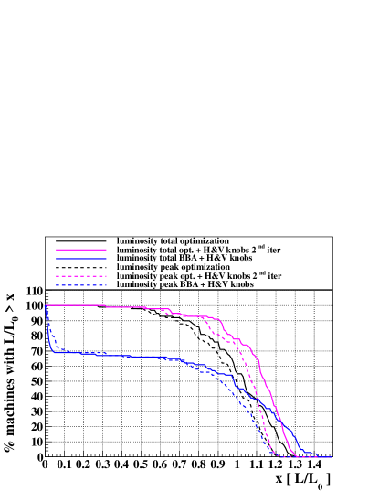
The results of the tuning of the BDS against magnets displacements are summarized in Fig. 1.
A random Gaussian displacement of each magnet with a of 10 m in the two transverse planes is considered, which is the pre-alignment specification in all the BDS. The number of machines reaching the target luminosity is quite different depending on the applied techniques. In order to accommodate for the static and dynamic imperfections the CLIC BDS lattice (with L∗=3.5 m) is designed to reach a peak and total luminosity higher than the nominal values, by 20 and 30, respectively. The target luminosity after the correction for the static imperfections is 110, the remaining 10, to reach the design peak luminosity of 120, is the budget for the dynamic imperfections. Here three different procedures are studied: BBA in combination with tuning knobs, luminosity optimization and luminosity optimization in combination with tuning knobs.
The Beam Based Alignment (BBA) technique consists of the 1-to-1 correction followed by Dispersion Free Steering (DFS) [10] in the vertical plane and target DFS in the horizontal one. In the 1-to-1 correction the beam is steered through the center of the BPMs. DFS is a technique that measures the dispersion along the line, using off-energy test beams, and corrects it to zero or to the nominal value. The energy difference of 0.1 is used to measure dispersion. The assumed BPM resolution in these simulations is 10 nm. This technique has proven successful in the CLIC collimation section alone, while it fails when the FFS is also considered. The possibility to use tuning knobs based on linear combinations of sextupoles displacements has been already explored in CLIC. Knobs to control the offsets and angles at the IP, the waist shift and the dispersions functions were partially successful. New tuning knobs are built here using FFS sextupoles displacements, in order to control mainly couplings, dispersions and waist-shift in the two transverse planes. These tuning knobs, applied after BBA, manage to shrink the transverse beam sizes close to the nominal values, recovering up to 50 of luminosity loss in half of the different seeds used in the simulation. Iterations of BBA and tuning knobs improve the correction. The final total and peak luminosity obtained after fifth iterations of this technique for 100 random misaligned machines are shown in Fig. 1 (blue line). About 30 of machines reach 110 of CLIC nominal luminosity. Of these about 15 exceed the design value of 130 for the total luminosity, while this is not the case for the peak luminosity. This effect is explained by the smaller horizontal beam size, reached after the BBA and FFS knobs scan, with respect to the nominal value, which causes on one hand the enhancement of total luminosity and on the other hand the emission of more beamstrahlung photons with the consequent increase of average energy loss that smears the luminosity spectrum in the energy peak.
In the luminosity optimization procedure, all the elements of the FFS
are moved in order to maximize luminosity, using the Nedler-Mead
algorithm (Simplex).
In this case more than 60 of the machines reach 110 of CLIC
total nominal luminosity.
It is worth noticing that when the luminosity optimization is combined
with tuning knobs about 90 of the machines reach 90 of CLIC
nominal total luminosity (Fig. 1).
The number of luminosity measurements needed by the luminosity
optimization procedure is one order of magnitude larger than the one
required by the BBA and Knobs scan technique.
It is therefore crucial for CLIC to be able to measure luminosity as
fast as possible (in the order of seconds) and to be able to tune the
system in the most efficient way.
The use of more sophisticated optimization algorithms and non linear
knobs could improve the overall luminosity results and reduce the
number of luminosity measurements required.
In the following we concentrate on the definition of fast luminosity
signals. For this purpose the beam-beam background processes
and their correlation with the main sources of luminosity degradation
are presented.
3 Luminosity signals and colliding beam parameters
We study the variation of different signals from beam-beam interaction, according to 10 different beam aberrations at the IP. The size of the aberrations is chosen to produce a luminosity loss of about 30. The six Signals (S) we define are:
-
1.
coherent – number of coherent pairs from the two beams;
-
2.
(nγ1+nγ2)/2 – average number of beamstrahlung photons from the two beams;
-
3.
1.0 - – difference of the number of beamstrahlung photons from the two beams normalized to their sum;
-
4.
nγ1/nγ2 – ratio of the number of beamstrahlung photons from the two beams;
-
5.
hadrons – total number of hadrons events;
-
6.
incoherent – total number of incoherent pairs from the two beams.
The full transport of the two beams through the main LINAC and the BDS is simulated with the tracking code PLACET [11]. The sextupoles of one beamline are displaced according to the linear knobs introduced in section 2, generating the beam phase space distortion at the IP. The second beamline instead is kept without any errors. Five of the knobs are built by horizontal sextupoles displacements in order to control horizontal dispersion (Dx), horizontal and vertical waist-shift (, ) and horizontal and vertical functions at the IP (, ). The other five knobs are built using vertical sextupole displacements, and they control vertical dispersion (E), vertical angular dispersion (E), and couplings (, ,).
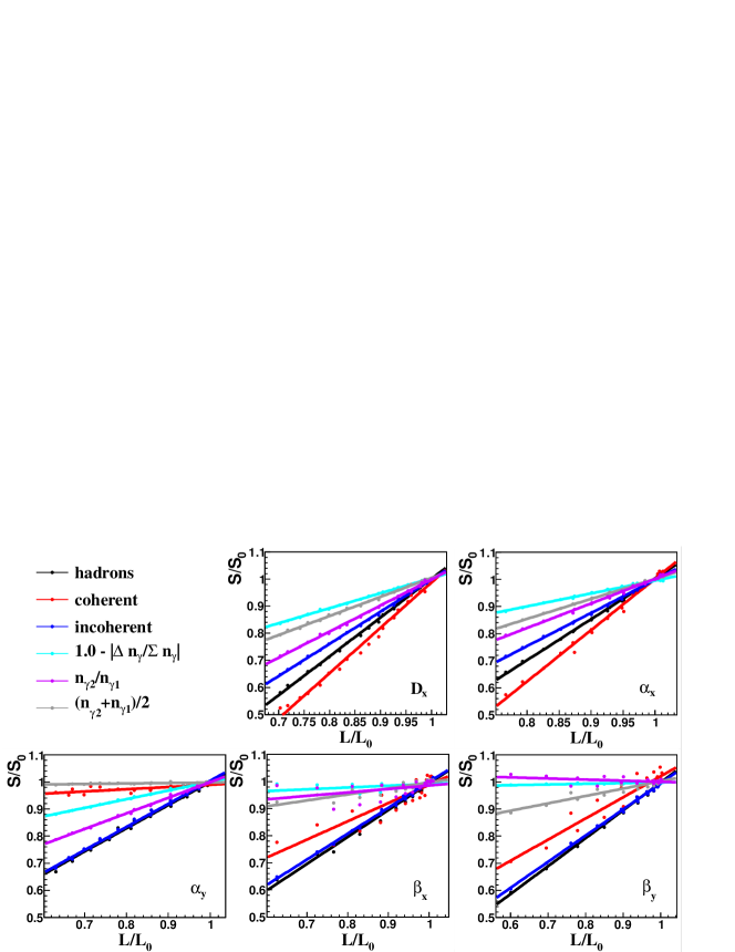
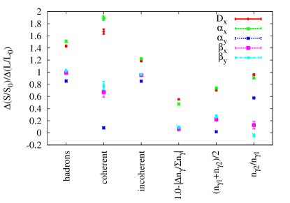
Figure 2 shows a fairly linear correlation of the six signals to the total luminosity in this range of scan of the knobs. The angular coefficients ((S/S0)/(L/L0)) obtained from the linear fits of the data points are shown in Fig. 3. The incoherent pairs signal presents an angular coefficient close to one (within 20 uncertainty) for all the five horizontal aberrations considered. The relative hadronic events rate shows the same behavior as the incoherent pairs except for horizontal dispersion and horizontal waist-shift. In these cases the number of collisions reduce faster than the incoherent pairs due to the larger reduction of average beamstrahlung photons (i.e. number of available for collisions). The relative change of these two types of processes follow the relative luminosity change independently of the beam aberrations that causes the luminosity loss within the 20 uncertainty. Therefore, incoherent pairs and hadronic events can provide an absolute luminosity measurement. With absolute luminosity measurement we mean here a signal whose rate changes proportionally to the luminosity, regardless of the aberrations considered. The correlation of the coherent processes with luminosity instead assumes quite different values according to the knob (i.e. aberration) considered. Therefore, signals from beamstrahlung photons and coherent processes, in combination with an absolute luminosity measurement, can be used to identify the main aberration of the two beams at the collision point, in dedicated feedback. The scan of the 5 vertical knobs gives similar results.
In practice, it is critical to define a signal that can be easily identified against the other processes. Experimental techniques to detect beamstrahlung photons in the CLIC post collision line can be found in [12]. The incoherent pairs are produced with relative small angles with respect to the beam axis, but are deflected by the beam fields. Therefore, the pairs particles can have large angles. The integration of pairs energy above a certain angle with respect to the beam axis has been studied as potential signal for luminosity optimization in [6]. In CLIC their detection could be more complicated due to the presence of the coherent pairs in the forward region, leptons coming from hadronic events and Bhabhas. In the following we discuss further the possibility to define a trigger using hadronic events by looking in particular at its multiplicity in the final state of the process.
4 Hadronic Events
Hadrons at linear colliders are produced by the process hadrons. The total hadrons cross section is known experimentally up to 200 GeV in the center of mass energy. The simplest model of the energy-dependence of the hadrons cross section () is the vector meson dominance one. The model assumes that the photon resonates to a hadronic state (a ) with a certain probability [15], with the energy dependence expressed as:
| (1) |
where and [16]. GUINEA-PIG implements the above parametrization of the total hadrons cross section. An electron or positron is replaced by the appropriate number of photons from the equivalent spectrum. The energies of the two colliding photons can be stored in a file and then loaded into PYTHIA [17], or an equivalent code, to generate the hadrons.
In order to define a region where the hadrons multiplicity can be detected two different cuts are applied to the charged particles. This ensure that they can travel in the forward detector region or in the detector main tracking region, considering a B-field of 5 Tesla. Following [18] we consider tracks with 0.050 GeV and 27 mrad 117 mrad for the forward region and tracks with 0.160 GeV and 117 mrad 1.57 rad for the main tracking region. The 27 mrad condition for the forward region is due to the envelope of the incoherent pairs while traveling in the detector solenoid magnetic field. The aim is to define a “background free” region to improve the quality of the identification of the signal against the other background sources.
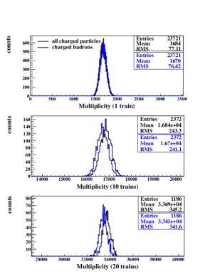
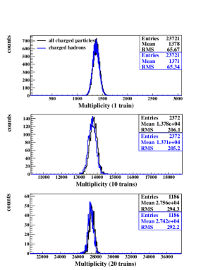
The resulting multiplicity distributions of all the charged particles and that of the hadrons, according to the selected angles and momenta, are shown in Fig. 4. The multiplicities are integrated over 1, 10 and 20 trains. Almost all the multiplicity from collision consists of charged hadrons. The detection of the hadronic component can be optimized in order to identify them against the lepton component or leptons coming from other processes. The mean value of the distribution over 20 trains is determined with about 1 fluctuation, which gives about 1.2 precision in the absolute luminosity measurement (due to the 20 uncertainty we discussed before). Given the CLIC repetition rate (50 Hz) 20 trains correspond to 0.4 seconds. Requiring a total time of 0.1 s for the read-out electronics and signal elaboration, one luminosity measurement should take about 0.5 s. Taking into account the number of luminosity measurement needed the total time to tune the BDS, starting from 10 m pre-alignment of the magnets, would be about 15 min when the BBA technique in combination with the FFS sextupoles knobs are applied, even if with low success rate. The total time required to tune the BDS with the luminosity optimization technique is instead of the order of 2 hours. Note that one full scan of the ten knobs takes 3 min, which is compatible with the requirement for the mitigation of the dynamic imperfections. The full CLIC detector model is not considered in these simulations. The actual amount of material and the interaction of these particles with matter should be considered in order to define the best region of detection of the signal, and minimize the number of bunches to sum in the trigger.
5 Conclusions
In order to mitigate the impact of magnet displacements in the CLIC BDS different techniques are compared. The best results reached so far are obtained by combining luminosity optimization and sextupole knobs scan: 90 of the considered machines reach 90 of CLIC nominal luminosity. In particular tuning knobs exploiting the sextupoles of the FFS have been proven a powerful tool to recover the luminosity loss due to magnet displacements. Tuning knobs and the luminosity optimization technique require a fast luminosity measurement. For this purpose the possibility to use hadrons background is investigated. The charged particles multiplicity from this process in the vertex-tracking and/or in the forward region of the detector could provide a signal for a fast luminosity measurement in less than 1 s with 1 precision. Given the number of luminosity measurements needed by the different alignment techniques here considered, the full tuning of the CLIC BDS against magnet displacements can be achieved in the range between about 15 min and 2 hours.
References
- [1] A. Latina et al., Alignment of the CLIC BDS CERN-AB-2008-011; CLIC-Note-753; EUROTeV-Report-2008-040.
- [2] R. Tomàs et al., ATF2 ultra-low IP betas proposal CERN-ATS-2009-092; EuCARD-CON-2009-058; CLIC-Note-792.
- [3] J. Pfingstner and J. Snuverink, Integrated simulations of dynamic imperfections and orbit feedback control for linear colliders, private comunication.
- [4] D. A. Karlen, A study of low Q2 radiative Bhabha scattering, Ph.D. Thesis, SLAC-325, 1988.
- [5] D. Schulte, New CLIC parameters, luminosity and background, presented in the CLIC 08 workshop at CERN, 14-17 October 2008.
- [6] D. Schulte, A potential signal for luminosity optimization in CLIC CERN-AB-2004-068; CLIC-Note-600.
- [7] P. Eliasson et al., Luminosity Tuning at the Interaction Point, CERN-AB-2006-044; CLIC Note 660; EUROTeV-Report-2006-039.
- [8] T. Tauki and K. Yokoya, Phys. Rev. E 51, 6119 (1995).
- [9] J. Snuverink et al., Status of Ground Motion Mitigation Tecniques for CLIC, IPAC11 proceeding and CLIC CDR.
- [10] T. Raubenheimer and R. Ruth, Nucl. Inst. Methods Phys. Res., Sect. A 302, 191 (1991).
- [11] D. Schulte et al., Simulation Package based on PLACET, CERN/PS 2001/028.
- [12] R.B. Appleby et al., CLIC post-collision line luminosity monitoring IPAC’11 proceeding.
- [13] D. Schulte, Study of Electromagnetic and Hadronic Background in the Interaction Region of TESLA Collider, PhD-Thesis, TESLA 97-98 (1997).
- [14] D. Schulte et al., Beam-Beam Simulations with GUINEA-PIG, ICAP98, Monterey, CA, USA (1998).
- [15] P. Chien et al., Hadron production in collisions as a background for e+e- Linear Colliders , Phys. Rev. D49, 3209 (1994).
- [16] G.A. Schuler and T. Sjostrand, gamma-gamma Physics at Linear Colliders, CERN-TH/96-119 (1996).
- [17] PYTHIA 6.4 physics and manual, JHEP 05 (2006) 026.
- [18] D. Dannheim and A. Sailer, Beam-induced backgrounds in the CLIC detector models, ALCPG Workshop, 19-23 March 2011, Eugene, Oregon.