Time-division multiplexing of the orbital angular momentum of light
Ebrahim Karimi1, Lorenzo Marrucci1,3, Corrado de Lisio1,3 and Enrico Santamato1,2
1Dipartimento di Scienze Fisiche, Università di Napoli “Federico II”, Complesso di Monte S. Angelo, 80126 Napoli, Italy
2CNISM-Consorzio Nazionale Interuniversitario per le Scienze Fisiche della Materia, Napoli, Italy
3CNR-SPIN, Complesso Universitario di Monte S. Angelo, 80126 Napoli, Italy
Abstract
We present an optical setup for generating a sequence of light pulses in which the orbital angular momentum (OAM) degree of freedom is correlated with the temporal one. The setup is based on a single -plate within a ring optical resonator. By this approach, we demonstrate the generation of a train of pulses carrying increasing values of OAM, or, alternatively, of a controlled temporal sequence of pulses having prescribed OAM superposition states. Finally, we exhibit an “OAM-to-time conversion” apparatus dividing different input OAM states into different time-bins. The latter application provides a simple approach to digital spiral spectroscopy of pulsed light.
OCIS codes: 050.4865, 270.5585, 230.6120
The orbital angular momentum (OAM) of light has been attracting an increasing interest in the last years, owing both to fundamental reasons and to its potential for multi-valued encoding of information, both in a classical and quantum regime [1, 2]. One key step in fully unreleasing this potential is to develop a convenient photonic technology for OAM generation, manipulation, and detection. The current OAM technology, e.g. including holograms and spatial light modulators (SLM) [3], spiral phase-plates [4], Dove prisms in suitable interferometers [5], etc., has important limitations in terms of ease of use, switching speed, cost, etc., so that the need for new solutions remains strong (see, e.g., [6]). In this paper, we propose a novel approach to OAM generation and detection based on setting up a correlation between this degree of freedom and the temporal one, for example within a regular sequence of optical pulses. This correlation can in turn be exploited to generate a time-to-OAM transfer of the information encoded in the optical field, or vice versa, depending on the details of the scheme.
Central to our approach is the -plate, a device allowing control of OAM by the light polarization (or photon “spin”) [7, 8]. A single -plate, however, couples the polarization with two values only of OAM. To address multiple OAM values one needs to cascade several -plates in sequence [9, 10]. Here, we consider an alternative scheme, as shown in Fig. 1, in which a single -plate is inserted in a ring optical cavity, so that a light pulse may undergo multiple passages through the same -plate, thus addressing multiple OAM values at different times.
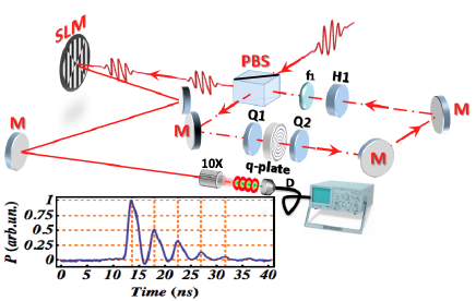
In our experiments, a titanium-sapphire laser operating at 1 kHz repetition rate generated pulses having a duration of about 130 fs. The ring cavity round trip time was about 4 ns. A fast photodiode connected to a 500 MHz oscilloscope was used for time-domain detection (see inset of Fig. 1). To analyze the setup workings, let us denote with an arbitrary polarization-OAM spinorbit state, where indicates the polarization, e.g. for left-circular, right-circular, horizontal, and vertical polarizations, respectively, and is an integer specifying the OAM eigenvalue. For simplicity we ignore in the following the radial mode profile. However, a lens imaging the -plate on itself after a round trip is needed to erase the radial profile transformations arising from propagation after the OAM is changed [10]. For so-called “optimal tuning” [11, 12], a -plate induces the following transformations in an optical mode having circular input polarization:
| (1) |
where is the (integer or half-integer) -plate topological charge. In our experiments we had , but we will keep the theoretical discussion general. Equations (S0.Ex1) show that each passage through the -plate can be used to shift the OAM value by , where the sign depends on the input polarization handedness (note that a spiral phase-plate could similarly shift the OAM at each passage, but in a fixed direction). If linear or elliptical polarizations are used at the -plate input, each passage will give rise to a superposition state of both the and shifted OAM values.
Let us first discuss the main loop occurring inside the ring cavity. Consider a pulse with OAM travelling inside the cavity, which has been just reflected by the polarizing beam-splitter (PBS) used as input/output port. The PBS is assumed to transmit the and reflect the polarization, so we take the pulse to be in state . The OAM is sign-inverted at each reflection, but we will ignore this effect that is finally compensated if the total number of reflections is even. The first quarter-wave plate (QWP) changes the input pulse into the superposition where and , being the angle at which the QWP optical axis is rotated with respect to the axis. After the -plate, the pulse is then cast in the spinorbit entangled state . The second QWP is oriented at an angle of , so that the pulse state at the end of the round trip, just before the PBS, is the following: . At the PBS, the component is reflected and starts a new cycle, while the component is coupled out of the cavity. The fraction of energy coupled out at each round trip is given by , which can be adjusted by rotating the first QWP. In our experiments we set , by taking . The pulse reflected at the PBS now has a shifted OAM and starts a new cycle which can be analyzed as the previous one. The output component has OAM . Let us now consider the first cycle after the input pulse has entered the cavity through the PBS, as this requires a distinct treatment. In this case, indeed, the pulse polarization is . Therefore, the coefficients and after the first QWP will be swapped (with a sign change for one), so that at the end of the first round trip the fraction of energy coupled out is . The second cycle starts with polarization and can be analyzed as discussed above.
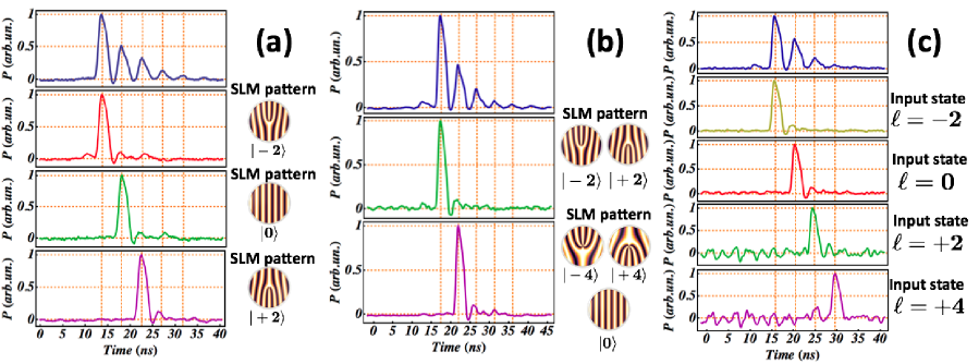
We consider now some specific applications of our setup. The first is for generating a sequence of pulses with increasing OAM, so that OAM and time bin of the pulse are correlated. This is obtained by entering the ring cavity with a first pulse with a given OAM, for example zero (i.e., a normal TEM00 gaussian beam). We will then obtain at the output the increasing-OAM sequence . The first output pulse (with ) will have a fraction of the input pulse energy, while the subsequent ones will have an energy fraction , where is the pulse number (or time bin) in the sequence. An example of this behavior is shown in Fig. 2a.
The OAM sequence can be also turned into decreasing, instead of increasing, by setting the second QWP at angle . In this case the output OAM sequence (for a gaussian input) will be . Another possibility is to set the second QWP to an intermediate angle, which gives rise to the following sequence of OAM superposition states (the polarization is omitted): , , , . The superposition coefficients can be partially controlled using the second QWP and the half-wave plate (HWP). For example, the OAM distribution can be made symmetric () by setting the second QWP and the HWP to an angle of zero. An example of this workings regime of our setup is shown in Fig. 2b.
Another possible application of our apparatus is for converting the input information encoded in OAM into time-bin encoding. The setup is essentially the same as before, but in the output of the PBS we add an OAM filter to detect selectively , for example by coupling the outgoing light into a single-mode fiber (without an intermediate SLM in this case). Then we operate the loop so as to decrease the OAM at each round trip. If the number of round-trips needed to observe a pulse in the output is , then the input OAM is given by . In other words, the time delay of the detected pulse is proportional to the input OAM value. This method is illustrated in Fig. 2c. We note that this method requires prior knowledge of the sign of the input OAM, so as to operate the shifter in the correct direction. An alternative possibility, when the OAM sign is unknown, is to operate the setup with the second QWP rotated at angle zero. In this way, the loop will create superposition states which include both increasing and decreasing values at each iteration, and the time bin of the first pulse giving a nonvanishing signal after the OAM filter will return the absolute value of the input OAM.
The detection efficiency of our setup for a given input is given by the same energy fraction given above for the generation case (not including the OAM filter efficiency). In our experiment we addressed only few OAM values because we set , giving rise to a rapid exponential decrease of the output energy, as . Higher OAM values, e.g. corresponding to pulse number , can be however reached by adjusting the output coupling factor to the optimal value (for ). This returns the optimized efficiency , which for high decreases only as . When the input pulse is in a superposition of different OAM components, more pulses are obtained at the output, with amplitudes corresponding to the input OAM power spectrum except for a rescaling by the detection efficiency . Therefore, the input OAM spiral spectrum can be visualized by a common oscilloscope. The same approach may be applied to single photons, although in its present form it would be a low efficiency method. The efficiency of our setup could however be substantially increased by adopting a fast Pockel cell to couple the light in and out, and, for the OAM-to-time conversion case, by replacing the PBS and subsequent OAM filter with a suitable hollow mirror, so as to let only the vanishing OAM state out of the cavity.
In conclusion, we reported a novel method for addressing multiple OAM values by coupling with the time degree of freedom. This approach may find applications in OAM-based quantum information schemes [13, 14] or in digital spiral imaging and microscopy [15, 16]. We acknowledge the financial support of the FET-Open Program within the 7th Framework Programme of the European Commission under Grant No. 255914, Phorbitech.
References
- [1] S. Franke-Arnold, L. Allen, and M. J. Padgett, Laser & Photon. Rev. 2, 299 (2008).
- [2] A. M. Yao and M. J. Padgett, Adv. Opt. Photon. 3, 161 (2011).
- [3] A. Mair, A. Vaziri, G. Welhs, and A. Zeilinger, Nature 412 313 (2001).
- [4] S. S. R. Oemrawsing, J. A. W. van Houwelingen, E. R. Eliel, J. P. Woerdman, E. J. K. Verstegen, J. G. Kloosterboer, and G. W. ’t Hooft, Appl. Opt. 43, 688 (2004).
- [5] J. Leach, M. J. Padgett, S. M. Barnett, S. Franke-Arnold, and J. Courtial, Phys. Rev. Lett. 88, 257901 (2002).
- [6] G. C. G. Berkhout, M. P. J. Lavery, J. Courtial, M. W. Beijersbergen, and M. J. Padgett, Phys. Rev. Lett. 105, 153601 (2010).
- [7] L. Marrucci, C. Manzo, and D. Paparo, Phys. Rev. Lett. 96, 163905 (2006).
- [8] L. Marrucci, E. Karimi, S. Slussarenko, B. Piccirillo, E. Santamato, E. Nagali, and F. Sciarrino, J. Opt. 13, 064001 (2011).
- [9] L. Marrucci, C. Manzo, and D. Paparo, Appl. Phys. Lett. 88, 221102 (2006).
- [10] E. Nagali, F. Sciarrino, F. De Martini, B. Piccirillo, E. Karimi, L. Marrucci, E. Santamato, Opt. Express 17, 18745 (2009).
- [11] E. Karimi, B. Piccirillo, E. Nagali, L. Marrucci, and E. Santamato, Appl. Phys. Lett. 94, 231124 (2009).
- [12] B. Piccirillo, V. D’Ambrosio, S. Slussarenko, L. Marrucci, E. Santamato, Appl. Phys. Lett. 97, 241104 (2010).
- [13] E. Nagali, L. Sansoni, F. Sciarrino, F. De Martini, L. Marrucci, B. Piccirillo, E. Karimi, E. Santamato, Nat. Photon. 3, 720 (2009).
- [14] E. Nagali, D. Giovannini, L. Marrucci, S. Slussarenko, E. Santamato, F. Sciarrino, Phys. Rev. Lett. 105, 073602 (2010).
- [15] S. Fürhapter, A. Jesacher, S. Bernet, and M. Ritsch-Marte, Opt. Express 13, 689 (2005).
- [16] L. Torner, J. Torres and S. Carrasco, Opt. Express 13, 873 (2005).