Adsorbate Transport on Graphene by Electromigration
Abstract
Chemical functionalization of graphene holds promise for various applications ranging from nanoelectronics to catalysis, drug delivery, and nanoassembly. In many applications it is important to be able to transport adsorbates on graphene in real time. We propose to use electromigration to drive the adsorbate transport across the graphene sheet. To assess the efficiency of electromigration, we develop a tight-binding model of electromigration of an adsorbate on graphene and obtain simple analytical expressions for different contributions to the electromigration force. Using experimentally accessible parameters of realistic graphene-based devices as well as electronic structure theory calculations to parametrize the developed model, we argue that electromigration on graphene can be efficient. As an example, we show that the drift velocity of atomic oxygen covalently bound to graphene can reach 1 cm/s.
Many unique properties of graphene – a monoatomic crystalline sheet of carbon – stem from the fact that it “lacks” volume and is, therefore, a truly 2d “all-surface” material Geim and Novoselov (2007). For instance, the surface functionalization of graphene (e.g., graphene oxide) provides an opportunity to alter electronic properties of the entire material, which holds promise in nanoelectronics Boukhvalov and Katsnelson (2008); Englert et al. (2011), nonvolatile memory Cui et al. (2011), graphene-based nanoassemblies for catalysis, photovoltaics and fuel cells applications Kamat (2010, 2011). In majority of these applications, the performance of a graphene-based device can be significantly improved provided there is a way to tune the surface functionalization in real time, i.e., during device operation. The related problem is to control and direct the transport of adsorbed atoms/molecules for nanoassembly Yang et al. (2008) and drug delivery applications Voloshina et al. (2011).
Electromigration is the drift of material on the surface (or in the bulk) of a current-carrying conductor Sorbello (1997). We propose to exploit electromigration as an efficient and easily controllable method to drive the directed transport of adsorbates on graphene. Very recently, and for the first time, the efficient electromigration of metallic clusters/atoms on graphene has been demonstrated experimentally Barreiro et al. (2011). In the current work, however, we focus on a different class of adsorbates (perhaps more relevant from the perspective of chemical functionalization) – atoms or molecules covalently bound to graphene. At first glance, the covalent binding may seem too strong to allow for efficient electromigration. Nevertheless, recent theoretical studies suggest the possibility of fast diffusion. Specifically, the activation energy for the atomic oxygen diffusion has been shown to drop from 0.7 eV for neutral graphene to 0.15 eV for -doped graphene, resulting in a diffusion coefficient as high as cm2/s Suarez et al. (2011).
In this Letter, we investigate electromigration of an adsorbate covalently bound to graphene, focusing on atomic oxygen (O) and the amino group (NH), as an example. In the lowest energy configuration, a single oxygen atom covalently binds to two adjacent carbon atoms of the graphene’s honeycomb lattice, thus forming an epoxy bond, Figs. 1(a)-1(d).

A single nitrogen atom can bind similarly, providing its third covalent bond for chemical functionalization, e.g., in drug delivery applications. In what follows, we develop a simple tight-binding model and obtain an analytical result for the drift velocity of an adsorbate as a function of its charge, the electric current in graphene, as well as the backgate doping level, and temperature. Specifically, we find that the migration (drift) velocity reaches up to cm/s at electrical current densities of A/mm and temperatures of K. The doping level and temperature dependence of the drift velocity are then used to formulate a robust adsorbate manipulation technique based on local heating of a graphene sample. This technique can become suitable for patterning and other applications involving direct access to the surface of graphene.
A particle (or defect) in contact with a conductor experiences an electromigration force which can be written as Sorbello (1997)
| (1) |
where , and are the absolute value of the electron charge, the charge of the particle in atomic units, and the vector of the external dc electric field (EF), respectively. The first term, the direct force , originates from the direct interaction of the adsorbate’s charge with the EF, as shown diagrammatically in Fig. 2(a).
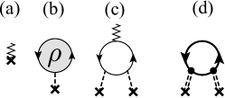
The second term, [Fig. 2(b)], originates from the scattering of electrons in graphene by the adsorbate-graphene interaction potential, ( is the position of the adsorbate). This contribution is often referred to as the electron wind force. Assuming the adsorbate structureless, i.e, treating as just a single-particle scattering potential, this contribution can be rewritten as
| (2) |
where is the single-particle density matrix and () creates (annihilates) a Bloch wave with quasimomentum . Equation (2) has a very appealing microscopic interpretation: it describes electron scattering from -state to -state within graphene, accompanied by momentum transfer to the adsorbate, with amplitude , see Fig. 1(a). The pitfall is that Eq. 2 is exact only for free electrons, and it can be nontrivial to justify that the momentum transfer is equal to the change of quasimomentum in the presence of band-structure effects Sorbello (1997). In what follows, we will show that the dominant contribution to is sufficiently smooth (as compared to the size of the graphene unit cell), so that Eq. (2) holds.
To obtain a closed expression for , the density matrix in Eq. (2) is expanded up to the leading order in . The validity of such perturbative expansion will be justified later when we address the graphene-specific form of . The first-order contribution in to vanishes exactly. The simplest nonvanishing contribution (second order in , first order in ) describes the interaction of an adsorbate with the current-carrying charge density of graphene, Fig. 2(c). Important processes not described by this diagram include (i) Coulomb-induced screening of and (ii) scattering due to impurities and phonons. Most diagrams containing such processes, as well as the effect of the EF, can be “lumped together” by dressing the adsorbate-graphene interaction using the random phase approximation and replacing bare electron propagators with fully dressed nonequilibrium (i.e., current-carrying) Green’s functions. As a result, the electron wind contribution to the electromigration force, depicted diagrammatically in Fig. 2(d), can be expressed as
| (3) |
| (4) |
where is the screened adsorbate-graphene potential. The steady-state distribution function in graphene is given by
| (5) |
in the linear response approximation Ashcroft and Mermin (1976). Here is the current density within graphene and is the Fermi-Dirac distribution; the Fermi momentum and the velocity of Dirac electrons in graphene are denoted by and , respectively. Equations (3) and (4) agree with the general (second-order) result for the wind force obtained earlier in Ref. Sorbello (1997). To complete the derivations we need to obtain , which is specific to the case of adsorbates on graphene.
The interaction potential between an adsorbate and graphene has two distinct contributions: . The first one, , describes the scattering of electrons in graphene by the Coulomb potential of the charged adsorbate. The second one, , describes the scattering due to the lattice defect caused by the covalent bonding of an adsorbate to graphene. As will become clear shortly, the Coulomb contribution is dominant and, therefore, we discuss it first.
In the backgated graphene with experimentally accessible electron densities, the screened Coulomb potential varies slowly over graphene unit cell, and it suffices to consider scattering only within a single Dirac cone. Within the lowest energy tight-binding description and the random phase approximation for screening, the Coulomb contribution can be cast in the form Rana (2007); Neto et al. (2009)
| (6) |
where is the Thomas-Fermi momentum. For graphene laid on top of a half-space dielectric substrate with the dielectric constant , the effective constant is given by Ponomarenko et al. (2009). In what follows, a SiO2 substrate with will be assumed. The angle stands for the angle between the vectors and , both measured with respect to the same Dirac point. The distance between the adsorbate and graphene, , is comparable to the graphene lattice constant, , and, hence, is negligible.
The effective size of the potential is given by , so that at eV (easily reached in backgated graphene) one has , and, therefore, . Therefore, the size of the potential is significantly larger than the unit cell, justifying both Eq. (3) and the neglect of scattering between the Dirac cones.
Using the inequality , the screened Coulomb potential of the adsorbate simplifies to . Substituting this expression, along with Eq. (5), into Eq. (4) and retaining only terms linear in , we finally obtain for the Coulomb contribution to the electron wind force Not
| (7) |
Here, the spin and valley degeneracies are lumped into the current .
To prove that the Coulomb contribution to the electron wind force is dominant, we estimate the amplitudes of Coulomb and lattice defect contributions. The covalent binding of an adsorbate to graphene alters the hybridization of the involved carbon atoms from to , see Figs. 1(b)-1(d). This amounts to cutting out the corresponding carbon orbitals from the tight-binding description of graphene, creating a lattice point defect. The lack of a single orbital can be mimicked by a fictitious impurity potential which cancels out the hopping integrals involving this orbital. For electrons near the Fermi circle such an impurity potential is essentially a delta function with a magnitude in momentum space of , where 2.8 eV is the hopping energy. Comparing and (screened or unscreened), we obtain
| (8) |
Since (see above), the contribution of the single-bond defect potential is small compared to that of the Coulomb potential at not too small . The actual defect potential leads to exclusion of several bonds, e.g., five for oxygen in the equilibrium state; see Fig. 1(d). Furthermore, the defect potential cannot be considered smooth on the scale of the unit cell, which might introduce significant band-structure effects [see the discussion following Eq. (2)]. Nevertheless, our analysis (not provided) using the accurate tight-binding model showed that these two complications do not change the qualitative conclusion that we have drawn: the contribution to the electron wind force is small compared to the Coulomb one and will be omitted henceforth.
Finally we note that the second-order representation of the wind force, Eq. (4) and Fig. 2(d), is sufficient for adsorbates with not very large . As will be seen shortly, 0.4 for both oxygen and nitrogen, and, therefore, the screened Coulomb potential is sufficiently small relative to the Fermi energy . At larger , multiple events of adsorbate-induced scattering of in-graphene electrons can modify the results obtained here.
The total driving force of the electromigration for a charged adsorbate on graphene is given by
| (9) |
where the effective charge of the adsorbate is introduced as and is the minimal conductivity of graphene Neto et al. (2009). Equation (9) – the main result of this work – expresses the total driving force of the electromigration via experimentally accessible parameters such as conductivity of graphene and the current density. The charge of the adsorbate, however, is not directly accessible, so we estimated it by performing electronic structure theory calculations using Gaussian 09 quantum chemistry package Frisch et al. . These calculations were performed using density functional theory with the PW91 functional Perdew et al. (1996) and the 6-311G** basis set for a number of graphene flakes of increasing size (up to ) to guarantee the convergence with respect to boundary effects. A single adsorbate was put in the center of a flake. The charges of the adsorbates were found in the range and , depending on the specific position of the adsorbate along the hopping trajectory [see Fig. 1(b)-1(d)], and the graphene doping level. The ratio of the electron wind and direct forces (or, equivalently, ) is shown in Fig. 3(b) (as a function of graphene conductivity Novoselov et al. (2005)) for the range of values.
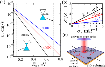
As is seen, the electron wind contribution dominates the electromigration force except for smallest or low conductivity,.
To calculate the drift velocity of an adsorbate on graphene due to electromigration, we use the Einstein–Smoluchowski relation between the diffusion coefficient, , and the drift velocity, , i.e.,
| (10) |
where Å is the hopping distance. The attempt frequency for oxygen was found to be THz in Ref. Suarez et al. (2011). We assume the same attempt frequency for the NH group, having in mind the approximate character of the calculations and the fact that the diffusion coefficient is not overly sensitive to variations of this parameter (compared to, e.g., the activation energy or temperature). The activation energy for oxygen diffusion, , as obtained in Ref. Suarez et al. (2011), is 0.7 eV for charge-neutral graphene, and a much lower value of 0.15 eV for -doped graphene with the charge density of cm-2. Our electronic structure theory calculations qualitatively confirm the strong sensitivity of the activation energy for oxygen diffusion. Furthermore, we found a similar dependence of the activation energy on doping level for NH adsorbate, albeit with somewhat higher activation energies (by eV). Figure 3(a) shows the dependence of the drift velocity on for =-0.3 at =1A/mm and =10-3 . Specifically, at these parameters and =0.15 eV the drift velocity is 6 mm/s at room temperature (=300 K) and reaches up to 4 cm/s at =500 K.
The increased drift velocity of the electromigration at higher temperatures can be used to perform adsorbate manipulations and patterning via a guided motion of adsorbates along the surface of graphene. This is most easily achieved by heating graphene locally with a focused laser beam [Fig. 3(c)], or by a heated AFM tip Wei et al. (2010). This local heating will enhance , while keeping the drift velocity low outside the heating spot by adjusting the doping level to lower values. As a result, it should be possible to move adsorbates along the desired path and assemble them into desired patterns by tracing the motion with the “local heater” and choosing the appropriate current directions via a set of source-drain contacts in perpendicular directions (typical, e.g., for Hall conductance measurements), see Fig 3(c). The spatial resolution of patterning is thermodynamically limited by the balance between diffusion and drift, and is given by van Kampen (1992). For the current density and conductivity used in Fig 3(a) we obtain nm K-1. For adsorbed oxygen atoms at K, the result in nm.
An experimental verification of an efficient electromigration of adsorbates on graphene can either be done using AFM/STM techniques to directly monitor diffusion/drift of adsorbates, or by optical means, e.g., adopting a nitrogen-based adsorbate with a fluorescent functional group and monitoring the fluorescence of such adsorbates with temporal and spatial resolution. Mapping a trajectory of adsorbates on carbon materials with finite band gap (e.g., carbon nanotubes) by photoluminescence quenching is an alternative strategy Crochet et al. (2012).
We thank Sergei Tretiak and Sergei Ivanov for consulting on electronic structure theory calculations. We also acknowledge valuable discussions with Ivar Martin, Tom Reinecke, and Chad Junkermeier. This work was performed under the NNSA of the U.S. DOE at LANL under Contract No. DE-AC52-06NA25396, and, in part, by ONR and NAS/LPS.
References
- Geim and Novoselov (2007) A. K. Geim and K. S. Novoselov, Nature Mat. 6, 183 (2007).
- Boukhvalov and Katsnelson (2008) D. W. Boukhvalov and M. I. Katsnelson, Nano Lett. 8, 4373 (2008).
- Englert et al. (2011) J. M. Englert, C. Dotzer, G. Yang, M. Schmid, C. Papp, J. M. Gottfried, H.-P. Steinrück, E. Spiecker, F. Hauke, and A. Hirsch, Nature Chem. 3, 279 (2011).
- Cui et al. (2011) P. Cui, S. Seo, J. Lee, L. Wang, E. Lee, M. Min, and H. Lee, ACS Nano 5, 6826 (2011).
- Kamat (2010) P. V. Kamat, J. Phys. Chem. Lett. 1, 520 (2010).
- Kamat (2011) P. V. Kamat, J. Phys. Chem. Lett. 2, 242 (2011).
- Yang et al. (2008) T. Yang, S. Berber, J.-F. Liu, G. P. Miller, and D. Tománek, J. Chem. Phys. 128, 124709 (2008).
- Voloshina et al. (2011) E. N. Voloshina, D. Mollenhauer, L. Chiappisi, and B. Paulus, Chem. Phys. Lett. 510, 220 (2011).
- Sorbello (1997) R. S. Sorbello, Solid State Phys. 51, 159 (1997).
- Barreiro et al. (2011) A. Barreiro, R. Rurali, E. R. Hernández, and A. Bachtold, Small 7, 775 (2011).
- Suarez et al. (2011) A. M. Suarez, L. R. Radovic, E. Bar-Ziv, and J. O. Sofo, Phys. Rev. Lett. 106, 146802 (2011).
- Ashcroft and Mermin (1976) N. W. Ashcroft and N. D. Mermin, Solid State Physics (Holt, Rinehart and Winston, New York, 1976).
- Rana (2007) F. Rana, Phys. Rev. B 76, 155431 (2007).
- Neto et al. (2009) A. H. C. Neto, F. Guinea, N. M. R. Peres, K. S. Novoselov, and A. K. Geim, Rev. Mod. Phys. 81, 109 (2009).
- Ponomarenko et al. (2009) L. A. Ponomarenko, R. Yang, T. M. Mohiuddin, M. I. Katsnelson, K. S. Novoselov, S. V. Morozov, A. A. Zhukov, F. Schedin, E. W. Hill, and A. K. Geim, Phys. Rev. Lett. 102, 206603 (2009).
- (16) Interestingly, does not enter Eq. (7), and, therefore, is not affected by the dielectric substrate. This cancellation occurs because the defect is screened by both the substrate and the doped graphene, and the strength of the latter contribution, , decreases when increases.
- (17) M. J. Frisch, G. W. Trucks, H. B. Schlegel, G. E. Scuseria, M. A. Robb, J. R. Cheeseman, G. Scalmani, V. Barone, B. Mennucci, G. A. Petersson, et al., Gaussian 09 Revision A.1, Gaussian Inc. Wallingford CT 2009.
- Perdew et al. (1996) J. P. Perdew, K. Burke, and Y. Wang, Phys. Rev. B 54, 16533 (1996).
- Novoselov et al. (2005) K. S. Novoselov, A. K. Geim, S. V. Morozov, D. Jiang, M. I. Katsnelson, I. V. Grigorieva, S. V. Dubonos, and A. A. Firsov, Nature 438, 197 (2005).
- Wei et al. (2010) Z. Wei, D. Wang, S. Kim, S.-Y. Kim, Y. Hu, M. K. Yakes, A. R. Laracuente, Z. Dai, S. R. Marder, C. Berger, et al., Science 328, 1373 (2010).
- van Kampen (1992) N. G. van Kampen, Stochastic Processes in Physics and Chemistry (North-Holland, Amsterdam, 1992).
- Crochet et al. (2012) J. J. Crochet, J. G. Duque, J. H. Werner, and S. K. Doorn, Nature Nanotech. 7, 126 (2012).