Positrons sources and related activities for Future Linear Collider at LAL Orsay Laboratory
Abstract
In the context of the positrons sources studies for the Future Linear Collider, the Accelerator Department at LAL Orsay is involved since several years in different activities both experiments and simulations.
1 Introduction
Basically the positron production requires an intense gamma flux (produced by a radiator) impinging on a target converter 111N.B.: in the case of conventional scheme the radiator and the converter are the same target.. The positron created are then trapped and accelerated into a capture section located downstream the converter.
Two solutions using two different radiator are under study :
-
1.
the Compton scheme based on circular polarized laser (baseline for polarized positron production at CLIC and an alternative for ILC) ;
-
2.
the hybrid scheme based on a crystal (baseline for unpolarized positron production at CLIC and under studied for ILC).
Concerning the capture section innovative concepts are under investigation.
2 The Compton scheme
![[Uncaptioned image]](/html/1201.6173/assets/x1.png)
2.1 Polarized positrons principle based on Compton scheme
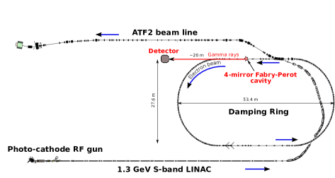
At Snowmass 2005, a polarized-positron source based on laser-Compton scattering was proposed for the ILC [1]. Circularly polarized laser photons are backscattered by an electron beam and the Compton photons materialize into longitudinally polarized pairs in a thin target. The correlation polarization-angle of this process shown in the opposite figure, give us the ability to select photon polarization using appropriate collimators . This allows, then, to control the positron polarization production.
However the low cross section of the Compton scattering requires a high current electron beam and high average power laser. To achieve such power (in the order of Megawatt) a Fabry-Perrot Cavity (FPC) is filled with a pulsed laser beam focused in a small waist allowing to reach a high power at the interaction point of the cavity. The use of a two mirrors cavity is unstable when one works in small mode waist. This is one of the reasons why four mirrors cavities is considered for Mighty laser experiment.
2.2 Mighty laser experiment at KEK
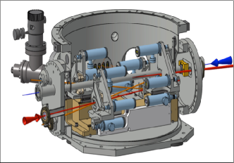
A prototype of such high finesse four-mirror FPC has been installed at the KEK ATF Figure 1(a) and is described in details in [2]. This prototype aims to contribute to a global R&D effort to reach the hundredth kW stored in such kind of cavity. A schematic drawing of this four mirrors cavity is shown Figure 1(b).
The optical system has been commissioned during summer 2010 and electron-photon collisions were observed on the first attempt in October 2010. Data analysis of this experiment can be found in [3]. Preliminary results are resumed on table 1 with respect to the electron beam pulse structure.
|
|
|
|
||||||||
|---|---|---|---|---|---|---|---|---|---|---|---|
| 1 train | 990 | 7% | |||||||||
| 2 trains | 1010 | 7% | |||||||||
| 3 trains | 1120 | 7% |
The MightyLaser project has demonstrated the production of gamma rays using a four mirror FPC. Next campaign to increase the number to gamma produced is under preparation.
3 Hybrid scheme
3.1 Presentation
CLIC considers as a baseline a method based on a combined crystal and amorphous tungsten targets : so-called the hybrid source [4]. A electron beam impinges on a tungsten crystal oriented on its axis [5]. To limit the energy deposition in the amorphous target, the charged particles are swept off after the crystal. Only the photon beam impinges on the amorphous target. In the goal of decreasing the energy deposition density in the converter some studies on the target geometry have been done. Concerning the simulation of the interaction of fast charged electron with the crystal a Geant4 event generator have been implemented with the partnership of IPN Lyon (France).
3.2 Converter study : granular amorphous target
The very intense incident electron beam considered in the linear collider projects requires resistant targets. Both concerning the total energy and the energy density deposited in the target converter. For the latter the Peak Energy Deposition Density (PEDD) is a critical parameter. In [6] the authors, using the experience of the target for muon collider, shown that using a granular target instead of compact reduces the PEDD (Table 2).
| t() |
|
|
N-Layers | N-Spheres | ) | ||||||
|---|---|---|---|---|---|---|---|---|---|---|---|
| Compact | 8.00 | 13.30 | 2.24 | 523 | 19.3 | ||||||
|
10.16 | 12.50 | 1.80 | 446 | 3 | 864 | 13.9 | ||||
|
11.60 | 13.45 | 2.33 | 613 | 7 | 8064 | 13.9 |
The high ratio of surface volume of the spheres () makes easier the thermal dissipation. In the scheme considered for the converter of the hybrid source, the spheres are arranged in staggered rows. The choice of the diameter of the spheres and of the number of rows is related to two quantities : the required positron yield and the PEDD. A comparison between two granular targets and a compact one giving close yield values is presented on Table 2.
3.3 Simulation
The radiation emitted from the interaction between a fast electron and the the individual atoms of an amorphous media is called incoherent bremsstrahlung. In crystalline targets and when the electron trajectory is close enough to a major crystallographic axis the amplitudes of the bremsstrahlung emission at certain wavelengths may interfere constructively. This will result in an enhancement of the intensity at this wavelength compared to ordinary incoherent emission.
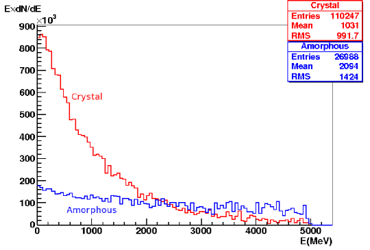
This type of radiation is called coherent bremsstrahlung. Moreover if particles enter with glancing angle to axis they may be trapped in ”channels” performing stable periodical trajectories along atoms rows or planes. This radiation is then called channeling radiation or Kumakhov radiation. Those physics processes have been implemented as an event generator for Geant4 [7]. Comparison of a amorphous and a crystal tungsten target with the same thickness are shown Figure 2. The large number of photon are used to impinge on a converter downstream the radiator [5].
4 Positron Capture pre-accelerating section
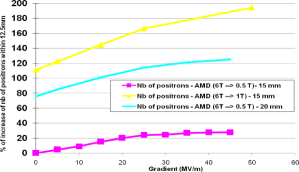
Due to the huge amount of multiple Coulomb scattering inside the converter, the positron beam has a large emittance and consequently is difficult to transport. Before being injected into to the damping ring to decrease their emittances the positrons should be trapped into specific magnetic device. The capture section is composed of an Adiabatic Matching Device (AMD) and a pre-accelerator encapsulated in a solenoid. The AMD has a large energy acceptance and hence increases the number of accepted positrons. At the end of the AMD the magnetic field is equal to the magnetic field solenoid which encapsulates the pre-accelerator. The studies for using a standing wave 4-cells cavity to accelerate the positron within the AMD have been investigated [8], the results of different senarios are shown Figure 3. The figures indicates the percentage of increase of the number of positrons as a function of the cavity gradient within the AMD field and considering the different maximum and minimum magnetic field.
Concerning the studies of the pre-accelerator itself two modes of operation could be applied. The first one is based on acceleration of the positrons straight after the AMD. This method have been already used in different collider. The second one requiere using the first accelerating structure in a decelerating mode such that a large number of positrons is captured [8].
The capture section studies have shown that the required number of positron at the end of the pre-accelerator for CLIC is matching the requirements.
5 Conclusion
The Accelerator Department at LAL Orsay has works in different aspect of the positron production for the future linear collider, from the production up to the capture section. Two theses are under preparation and will be submitted before the end of 2012.
6 Acknowledgments
The collaborators include X. Artru & R. Chehab (IPN Lyon France) and V. Strakhovenko (BINP Novosibirsk Russia).
References
- [1] S.Arakietal, KEK-Preprint 2005-60, CLIC Note 639 (2005).
- [2] J. Bonis, R. Chiche, R. Cizeron, M. Cohen, E. Cormier, P. Cornebise, N. Delerue and R. Flaminio et al., arXiv:1111.5833 [physics.acc-ph].
- [3] T. Akagi, S. Araki, J. Bonis, I. Chaikovska, R. Chiche, R. Cizeron, M. Cohen and E. Cormier et al., arXiv:1111.5834 [physics.acc-ph].
- [4] Artru X. et al., Polarized and unpolarized positron sources for electron-positron colliders, Nucl. Instruments and Methods in Physics Research Section B: Beam Interactions with Materials and Atoms 266 (2008) 3868-3875.
- [5] O. Dadoun et al. The Baseline Positron Production and Capture Scheme for CLIC. 1st International Particle Accelerator Conference: IPAC10, 23-28 May 2010, Kyoto, Japan.
- [6] C. Xu, R. Chehab A positron source using axially oriented crystal associated to a granular amorphous converter, LAL/RT 12-01. To be published in chinese physics C.
- [7] O. Dadoun, to be published in Radiation from Relativistic Electrons in Periodic Structures 2011.
- [8] F. Poirier Dynamics of the positron capture and accelerating sections of CLIC, CLIC-Note-877.