NUCLEAR PHOTONICS
Abstract
With the planned new -beam facilities like MEGa-ray at LLNL (USA) or ELI-NP at Bucharest (Romania) with /s and a band width of , a new era of beams with energies up to 20 MeV comes into operation, compared to the present world-leading HIS facility at Duke University (USA) with and . In the long run even a seeded quantum FEL for beams may become possible, with much higher brilliance and spectral flux. At the same time new exciting possibilities open up for focused beams. Here we describe a new experiment at the beam of the ILL reactor (Grenoble, France), where we observed for the first time that the index of refraction for beams is determined by virtual pair creation. Using a combination of refractive and reflective optics, efficient monochromators for beams are being developed. Thus, we have to optimize the total system: the -beam facility, the -beam optics and detectors. We can trade intensity for band width, going down to and address individual nuclear levels. The term “nuclear photonics” stresses the importance of nuclear applications. We can address with -beams individual nuclear isotopes and not just elements like with X-ray beams. Compared to X rays, beams can penetrate much deeper into big samples like radioactive waste barrels, motors or batteries. We can perform tomography and microscopy studies by focusing down to m resolution using Nuclear Resonance Fluorescence (NRF) for detection with eV resolution and high spatial resolution at the same time. We discuss the dominating M1 and E1 excitations like the scissors mode, two-phonon quadrupole octupole excitations, pygmy dipole excitations or giant dipole excitations under the new facet of applications. We find many new applications in biomedicine, green energy, radioactive waste management or homeland security. Also more brilliant secondary beams of neutrons and positrons can be produced.
Keywords:
beam, optics, nuclear photonics:
07.85.Fv, 25.20.-x, 29.25.Dz1 INTRODUCTION
Here we consider tunable beams with typical energies from 0.1 - 20 MeV from hard X-rays to beams. Some of the properties of these beams, like their wave length, or the real part or imaginary part of the index of refraction for a typical material like silicon and gold are compiled in Table 1. The refractive part , where is the scattering length and the atomic density. The absorptive part , where is the absorption cross section and the absorption coefficient. For photons we have the relation between the wavelength in fm and the photon energy in MeV
| (1) |
The new optics Habs (2011) with small radii of curvature works best for rather brilliant beams with a rather small beam diameter. Thus, we have to compare the properties of planned and existing beam facilities to the requirements of the optics.
| energy | wavelength | (Si) | (Si) | (Au) | (Au) |
|---|---|---|---|---|---|
| 10 MeV | 124 fm | ||||
| 1 MeV | 1240 fm | ||||
| 0.1 MeV | 0.124Å | ||||
| 12.4 keV | 1.0Å |
In Table 2 we have compiled these properties. For the newly planned Compton back-scattering -beam facilities like MEGa-ray Barty (2011) and ELI-NP ELI-NP (2011), we expect to get much more brilliant and much more intense beams, compared to the present worldwide best values of the HIS facility Weller (2009). However, the large distance of about 30 m for HIS from the production point of the beam to the first access of optics results in a large -beam diameter of 1 cm, too large for an effective use of lenses. On the other hand, for MEGa-ray and ELI-NP first beam diameters of about 50 m are accessible for an energy spread of , well suited for optics. For hard X-ray beams of the ESRF facility (Grenoble) at the high energy beam line ID15 typical beam diameters are less than 1000 m, again suited for X-ray optics Snigirev (2011). The smaller beam size allows for smaller optical elements with less absorption. Then more elements N can be used behind each other increasing the deflection. On the other hand, we have rather small opening angles of the beams. Thus, a small angle change makes the divergent beam convergent. We have to use rather long flight paths (several 10 meters) to reach even smaller -beam diameters, which then make optics even more effective. Thus, similar to hard X-ray experiments at large synchrotrons, rather long beam lines are required for -beam experiments.
We have to look at the three components: (i) the beam (ii) the optics (iii) the detectors as an integral system and have to tailor them for each experiment. Frequently, there is a clear need to reduce the average -beam intensity or the instantaneous intensity on target, but we should not just reduce it by collimators, but we should improve at the same time the band width from an expected value of to, e.g., . It may be advantageous to have the possibility to gradually zoom in the beam resolution, to identify first interesting spectral structures with lower resolution and then to increase the beam resolution accordingly.
| property | HIS | MeGa-ray | ELI-NP | QFEL | ESRF(ID15) |
|---|---|---|---|---|---|
| energy [MeV] | 1-160 | 0.5-2.7 | 0.5-19.6 | 0.5-10.0 | 0.1-0.70 |
| peak brilliance | |||||
| 1/(mm2mrad2s BW) | |||||
| intensity [1/s] | |||||
| spect. flux [1/(eV s)] | |||||
| band width | |||||
| opening angle at 1 MeV | |||||
| closest beam radius [m] | |||||
| repetition rate [1/s] |
2 INTEGRATED BEAM FACILITIES
2.1 Beams
For the two planned Compton back-scattering facilities ELI-NP and MEGa-ray we expect for all energies. For Compton back-scattering there is a relation between energy and the angle of the outgoing photon with respect to the electron beam direction:
| (2) |
is energy of the primary laser photons, is the factor of the electron beam with energy and the electron rest mass . Thus, for the emitted photon has about a factor of 2 smaller energy than a photon in electron beam direction. For angles , the central beam opening cone shows no longer the dependence of the Compton scattering, but other factors like the band width of the electron beam or the band width of the laser beam determine the band width BW of the beam. We will limit the acceptance angle of the lens or the corresponding beam radius at the entrance to the lens to this much smaller angle . Thus we make use of the very special energy – angle correlation of Compton back-scattered rays to work with a very small radius and to obtain a natural monochromatization. For a band width , we thus expect for ELI-NP and MEGa-ray an intensity of /s. The outer angles are no longer focused by the lens.
2.2 Optics
Refractive Optics
In the last 15 years, X-ray optics became very common at many synchrotron beam lines nielsen (2001); Snigirev (2011). The refractive index of X-ray lenses is determined by the virtual photo effect (Rayleigh scattering) and follows the law lengeler99 :
| (3) |
The ray wave length is measured in Å, in , is the atomic number and is the atomic mass in . Obviously, converges with very fast towards zero, which represents a significant limitation for the construction of focusing optics at higher energies via . A way to still obtain a reasonable focal length is to combine a large number of lenses with
| (4) |
where is the radius at the apex of the parabolically shaped,
concave lenses.
However, recently Habs (2011) we observed that the index of refraction for energies above 700 keV is positive in silicon (Z=14), and no longer negative like for X-rays. For 1-2 MeV rays we obtained still rather small values of . While for X-rays the virtual photo effect (Rayleigh scattering) explains , for the higher energies it is the virtual pair creation or Delbrück scattering. Here no longer the electrons, but the electrostatic fields (beyond the Schwinger limit) of the nuclei dominate the scattering amplitude. Since the pair creation (Bethe-Heitler process) scales with , we expect due the the Kramers-Kronig dispersion relation, that also contains in a power series development with a term proportional to . But Delbrück scattering, which scales with , is for larger angles an absorptive process and we expect from the Kramers-Kronig dispersion integral that contains also a strong term scaling with . Extending the same procedure to higher-order Delbrück scattering and pair creation, also contains in the expansion higher terms . Even if the factors in front of are small, for higher-Z materials these terms may start to dominate. Thus we expect for typical high Z optical materials like gold or platinum, that the index of refraction may reach values for 1-2 MeV rays. This large increase of with Z is essential for all optics and has to be verified experimentally. If larger values of can be reached, smaller numbers of optical elements are required to obtain the same deflection. Also, the switch-over from negative to positive values of will occur for higher-Z materials at lower energy. For energies below, e.g., 100 keV, the large increase of the photo effect with probably makes high Z optical elements inefficient. On the other hand, we have for gold above 0.5 MeV an absorption length of 3 mm, which is quite large.
Thus, we expect for -beams that high-Z materials like gold or platinum will become the ideal material for all optical elements like lenses, prisms etc.. While for X rays due to the negative concave lenses are used for focusing, for rays convex lenses like in standard classical optics will be used. The new shows a very different, much more favourable energy dependence: it is rather constant below 3 MeV and drops off with for larger energies. Thus optics may be extended up to 10-20 MeV. In contrast showed the much faster decrease with . Typical lenses at the beam entrance could have a radius of curvature of 500 m, a central thickness of 150 m and an acceptance diameter of 250 m.
New Efficient Monochromator: Combination of Refractive and Reflective Optics
Monochromatization of electromagnetic radiation via Laue or Bragg diffraction follows Braggs law
| (5) |
Here is the wave length of the incoming photon, the lattice spacing of the diffracting crystal, is the order of reflection and the diffraction angle. We have a typical deflection angle of 10 mrad for 1 MeV rays. This Bragg diffraction is a well established monochromatization technique nielsen (2001). A particular role in these considerations play so called perfect single crystals, where a coherent propagation of an incoming wave field all through the crystal occurs. Within dynamical diffraction theory nielsen (2001); Petrascheck (1984) it can be shown that the angular dependence of the intensity profile , under which an incoming wave field is diffracted, has the following analytical form
| (6) | |||||
| (7) |
Here is a crystal specific parameter which linearly depends on the wave length. It can be easily demonstrated from Eq. (6) that the width of is proportional to . This width should be called the acceptance width of the monochromator crystal. In order to obtain the excellent and wave-length independent possible monochromatization of an ideal crystal, it is necessary to create a beam with a divergence not larger than the acceptance width of the monochromator. This can be obtained by the use of a double-crystal monochromator Kessler (2001); Petrascheck (1984). The beam accepted and diffracted by a first perfect crystal (in that sense the beam behind the first crystal) will have a divergence equal to the acceptance of this first crystal. If a second crystal, identical to the first one, is placed into this beam, the acceptance and divergence are perfectly matched and the theoretical possible monochromatization can be obtained. The second crystal operates at a different order of reflection for the dispersive mode, while the first crystal produces a narrow width in angle, which translates into a narrow energy width for the second crystal:
| (8) |
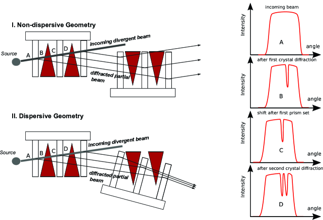
This concept of monochromatization is largely used at X-ray synchrotrons, where the angular Darwin width is nicely matched to the natural opening angle . Since the acceptance of the first crystal quickly gets much smaller with wave length compared to the divergence of the incoming -beam, for -ray energies these intensity losses amount to 3-4 orders of magnitude. We want to pursue a new technical solution that allows to overcome these enormous losses in intensity associated with the use of perfect single crystals. The main idea consists in the combined use of refractive optics and diffraction monochromators and is illustrated in Fig. 1. We propose to use instead of a single monochromator crystal a sequence of several crystals. To assure that each crystal has the same lattice spacing and the same orientation, we propose to cut them from a single large crystal block. In this sense each crystal sheet will act as a perfect monochromator crystal. Between the crystal sheets we propose to insert a system of one or several refracting prisms. The function of this combined system is illustrated in the right hand part of Fig. 1. The upper graph (A) illustrates the divergent beam profile of the incoming photon beam. The next graph (B) shows the beam profile after the action of the first monochromator crystal sheet. It is indicated that a fraction of intensity is missing due to the diffraction process. In graph (C) we show how the prism system is acting: it is shifting the intensity profile in angular space (rotating it). By this it assures that the next monochromator crystal sees again the full intensity. The action of the next monochromator stage is shown in plot (D). It is important to notice that the action of the refractive prism should shift the intensity as much as the acceptance width of each single crystal sheet would be. A sequence of crystal sheets and refractive prisms is supposed to replace a single monochromator crystal within a double-crystal monochromator setup. The parallel single crystal slabs require a certain thickness, depending on the photon energy but typically 1-5 mm. Due to the negligible absorption in the crystals and wedges, the process can be repeated typically 10 -100 times. Since we will first match the incoming beam with a lens system to the monochromator system, we expect in the range of 0.1 - 20 MeV a further improvement in the order of 10 -100, getting close to a reduction in intensity just by the factor of corresponding to the ratio of initial energy resolution to the final energy resolution .
3 Applications
In the discussion of possible -beam applications we first consider the cross section of photonuclear reactions and the width . The cross section for a compound nucleus resonance populated by photo-excitation at the resonance energy in the region below the neutron separation energy is given by the Breit-Wigner formula Segr (1977)
| (9) |
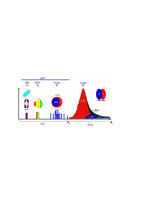
where is a spin factor for the spin of the target and the beam and represents the wavelength of the rays with energy . The resonance is excited with the width and decays via the width . The resonance has a total width . Fig. 2 shows the dominant E1 and M1 nuclear excitation widths .
The typical maximum E1 width for a level up to the neutron separation energy is about 10 milli-Weisskopf units. It corresponds for 2 MeV photons to about 0.1 eV. On the other hand, the Doppler broadening of a transition at room temperature eV for a nucleus with mass number and a energy = 2 MeV is
| (10) |
It shows that we find a typical relative line width of for a nucleus with a mass number A=50 or 1 eV at 1 MeV and 10 eV at 10 MeV, respectively. Thus with a beam of band width we can selectively address individual nuclear levels within their Doppler width. Since the maximum nuclear cross sections are typically 1 kbarn for 1 MeV and thus much larger than atomic cross sections of 1 -10 barn for Compton scattering and pair creation, we can strongly reduce the atomic background. At the same time the deexcitation cascades of individual levels are much less complex than when exciting a multitude of levels at the same time.
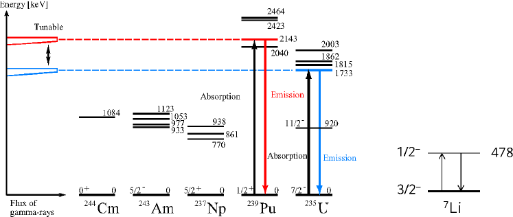
Now, let us consider the M1 and E1 excitations of Fig. 2 as strong excitations for potential applications. The low-lying M1 excitation can be employed via Nuclear Resonance Fluorescence (NRF) using focusing lenses for tomography and microscopy with m resolution Schroer (2010). In Fig. 3 we show M1 excitations for actinides, which can be used in nuclear fuel assay or radioactive waste monitoring. Based on the M1 transition in 7Li (478 keV) we can, e.g., perform a high resolution tomography of growing defects in Li batteries or in medical physics we can study the distribution of Li in the brain during treatment of manic depressive alternating insanity.
Due to their internal structure, the higher QOC E1 excitations frequently decay by quadrupole transitions to higher-spin states. We want to use this feature to populate high-spin isomers like 195mPt to produce medical radioisotopes for diagnostics and therapy Habs (2011b).
We envisage to use the pygmy resonance to populate very weakly bound neutron states just below from the stable ground state by an E1 excitation. These weakly bound states are isomers, because the neutron tunnels out very far. With a second laser we can release this neutron, generating a very brilliant neutron source Habs (2011a). Also a very brilliant secondary positron source can be produced from high-Z foils of e.g. platinum with a 1.5-2.0 MeV -beam via the Bethe-Heitler pair creation process Hugenschmidt (2011). We also proposed the production of many new medical radioisotopes via the giant dipole resonance Habs (2011b). Compared to X rays, one of the main advantages of rays is their deep penetration. With the new optics many new isotope specific tomographic studies become possible.
In the future we plan to increase the intensity of very monochromatic, very directed Compton back-scattered -beams by a factor of about , seeding the emission of a quantum FEL Bonifacio (2011, 2011); Günther (2011). This would result in the possibility of many large scale industrial applications, but also a new field of coherent -ray physics paganin (2006) with much larger coupling strength would open up.
References
- Habs (2011) D. Habs et al., The Refractive Index of Silicon at Ray Energies submitted to Phys. Rev. Lett, arXiv:1111.3608v1[physics.atom-ph], (2011).
- Barty (2011) C. Barty (LLNL),http://www.eli-np.ro/documents/meeting-18-19-august-2011/Presentations/Barty-LLNL-Gamma-Source-for-ELI-NP.pdf
- ELI-NP (2011) ELI-NP http://www.eli-np.ro/
- Weller (2009) H.R. Weller et al., Prog. Part. Nucl. Phys. 62, 257 (2009).
- nielsen (2001) J. Als-Nielsen and D. McMorrow, Elements of Modern X-Ray Physics, John Wiley, New York, (2001).
- paganin (2006) D.M. Paganin, Coherent X-Ray Optics, Oxford University Press, Oxford, (2006).
- Snigirev (2011) G.B.M. Vaughan et al., J. Synch. Rad, 18, 125 (2011).
- (8) B. Lengeler et al., J. Synch. Rad. 6, 1153 (1999).
- Kessler (2001) E.G. Kessler et al., Nucl. Instr. Meth. A 457, 187 (2001).
- Petrascheck (1984) D. Petrascheck and H. Rauch, Act. Cryst. A40, 445 (1984).
- Schroer (2010) C,G, Schroer et al., Act. Phys. Pol. A 117, 357 (2010).
- Segr (1977) E. Segr, Nuclei and Particles, W.A. Benjamin, Inc. London (1977).
- Habs (2011b) D. Habs et al., Appl. Phys. B 103, 501 (2011).
- Habs (2011a) D. Habs et al., App. Phys. B 103, 485 (2011).
- Hugenschmidt (2011) C. Hugenschmidt et al., Appl. Phys. B , DOI 10.1007/s00340-011-4594-0 (2011)
- Bonifacio (2011) R. Bonifacio et al.; Optics Comm. 284, 1004 (2011).
- Bonifacio (2011) R. Bonifacio et al., Fortschritte der Physik, 57, 1041 (2009).
- Günther (2011) M.M. Günther el. al., contribution to this LEI2011 conference.