Spin-orbit field switching of magnetization in ferromagnetic films with perpendicular anisotropy
Abstract
As an alternative to conventional magnetic field, the effective spin-orbit field in transition metals, derived from the Rashba field experienced by itinerant electrons confined in a spatial inversion asymmetric plane through the s-d exchange interaction, is proposed for the manipulation of magnetization. Magnetization switching in ferromagnetic thin films with perpendicular magnetocrystalline anisotropy can be achieved by current induced spin-orbit field, with small in-plane applied magnetic field. Spin-orbit field induced by current pulses as short as 10 ps can initiate ultrafast magnetization switching effectively, with experimentally achievable current densities. The whole switching process completes in about 100 ps.
Ultrafast manipulation of magnetization is currently under intense investigation, partly driven by the ever increasing demand in information industry, partly inspired by the intriguing physics involved. Traditional methods use pulsed magnetic field to realize ultrafast switching of magnetization, through the spiral motion of magnetization in a magnetic field, applied in the inverse direction of the magnetization. However, due to domain wall instability kashuba06 , ultrashort field pulses bring about stochastic behavior, thus imposing limitations on the ultimate switching speed tudosa04 . In practice, the limitation on this switching scheme is related to the difficulty in the generation of picosecond, strong magnetic field pulses, which entails the use of relativistic electron bunches nowadays. Precessional switching scheme, in which the magnetic field is applied perpendicular to the initial magnetization direction, circumvents this problem by maximizing the precession torque experienced by the magnetization back . The deficit of precessional switching is manifested by the needed precise control of the pulse duration, on the time scale of the magnetization’s precession period. Instead of the conventional magnetic field, alternative means, such as light kirilyuk10 , electric field ohno00 and electric current stt , can be used to manipulate magnetization. Recently, the effective spin-orbit field acting on the magnetization attracts much attention because of its potential applications. This spin-orbit field in transition metals results from the Rashba field bychkov84 experienced by itinerant electrons confined in a spatial inversion asymmetric potential through the s-d exchange interaction manchon . Reversible switching of magnetization in perpendicularly magnetized Co nanodots was already demonstrated miron11 , making the speculation of employing the spin-orbit field to control magnetization in ferromagnetic metals more than mere imagination, although the underlying mechanism responsible for the observed switching is still elusive. It is proposed, as will be shown in the following by macrospin simulation, that the pure spin-orbit field, in combination with the precessional motion induced by it, can explain qualitatively the observed experimental results . In addition, the feasibility of precessional switching utilizing the spin-orbit field will be addressed as well. It is found that, due to the large anisotropy and spin-orbit fields, both derived from the large spin-orbit coupling characteristic of systems with large perpendicular magnetocrystalline anisotropy (PMA), the switching time can be as short as 100 ps.
The prototype material system considered here is a trilayer Pt/Co 6 Å/AlOx nanodot, which is a representative of thin ferromagnetic metallic nanostructures with PMA. The strong perpendicular anisotropy results from the 3d-5d hybridization at the Pt/Co interface and the 3d-2p hybridization at the Co/AlOx interface rodmacq09 . The asymmetry of the top and bottom materials introduces a spin-orbit field for 3 electrons confined in the thin Co layer. If current flows along the direction (c.f. Fig. 2 for the coordinate system used), and the trilayer structure lies in the plane, then the spin-orbit field is Bso = ( j), where is a unit vector along the axis, j is the current density, and is the spin-orbit field constant, which is proportional to the spin-orbit coupling in Co. For the optimized thickness of Co considered here, could be very large, = 10-12 T m2/A miron10 . The induced large spin-orbit field by injecting high density current into the sample could have profound effects on the magnetization dynamics.
In the macrospin approximation, the uniform magnetization M is treated as a macroscopic spin, whose dynamics is governed by the Landau-Lifshitz-Gilbert (LLG) equation llg
| (1) |
where m = M/ is the normalized magnetization vector ( is the magnitude of M), = 1.76 1011 Hz/T is the free-electron gyromagnetic ratio, and is the phenomenological Gilbert damping constant. The total magnetic field B = Ba + Bapp + Bso is a sum of the anisotropy (Ba), applied (Bapp) and spin-orbit (Bso) fields. In the simulation, the current flow in Co is along the axis, while the magnetic field is applied in the plane, 3∘ tilted away from the axis. The Gilbert damping is chosen to be = 0.3 alpha . The perpendicular anisotropy field has the form Ba = , with = 0.92 T miron10 . To stabilize the perpendicular magnetization configuration, an external field = 5 mT is added to the total field, depending on the initial magnetization orientation.
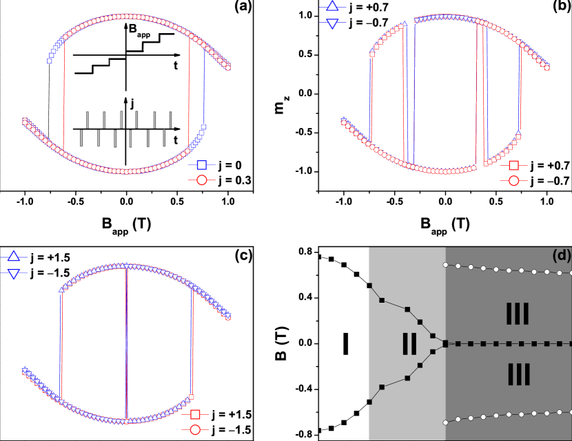
To investigate the effect of the spin-orbit field on the switching behavior, the time sequence for the applied field and current pulses, as shown in the insets of Fig. 1(a), is considered. Essentially, a hysteresis loop is simulated. But at each field value, current pulses with both polarities, positive and negative, are applied consecutively. The equilibrium magnetization direction after each pulse is then recorded. The current pulse is modelled by a 10 ns square wave with infinitely sharp rising and falling edges. The spin dynamics under the influence of current is dictated by the LLG equation, Eq. (1). At the rising edge, due to the fact that the length of the current pulse is longer than the characteristic time scale of the magnetization dynamics triggered by the sudden application of current, the magnetization stops precessing far before the current pulse is terminated. Once the falling edge of the current pulse is reached, the magnetization vector will start precessing again, damping to a different equilibrium position, depending on the polarity of the current pulse. The component of the normalized magnetization, , after positive and negative current pulses, as a function of the applied field, is shown in Figs. 1(a), 1(b) and 1(c). The current, or the corresponding spin-orbit field, effect can be clearly observed: When the current density is lower than 5 1011 A/m2 ( = 0.5 T), only the coercivity is decreased (Fig. 1(a)). By increasing the current density to well above 1 1012 A/m2 ( = 1 T), projection of the magnetization onto the axis is completely determined by the polarity of the current (Fig. 1(c)). Deterministic switching controlled by the polarity of current occurs. In the intermediate region, current controlled switching is effective only for a narrow field interval (Fig. 1(b)). Fig. 1(d) gives an overview of the different switching behavior of the magnetization, for current density ranging from 0 to 2 1012 A/m2. It can be seen that the coercivity decreases to zero with increasing current, while the maximum field for current induced switching remains almost constant, in agreement with experiment miron11 .

The physical mechanism responsible for the reversible, current induced switching can be understood by tracking the magnetization precession in time. In Fig. 2, two typical precession traces corresponding to = 1.5 1012 A/m2 and = 0.3 T are shown. The influence of the polarity of the current is obvious. It determines whether the magnetization will spiral upward or downward, initially. If the applied magnetic field is not too large, which means that the magnetization orientation pointing up or down is well separated, this initial discrepancy will lead to the difference in the final equilibrium position, i.e. whether the magnetization is pointing up or down. Effectively, the final orientation of the magnetization is defined by both the spin-orbit field and the applied field, through the cross product Bso M cross , which is nothing but the initial torque experienced by the magnetization when the current is turned off. This is consistent with the symmetry required by the perpendicular switching scheme miron11 . In the intermediate region (Fig. 1(b)), the spin-orbit torque is not large enough to induce switching by itself, applied field is required to overcome the action of anisotropy. If the applied field is not large enough, the equilibrium stays finite even in the presence of the spin-orbit field, because of the large PMA. When the current is removed, the magnetization never goes across the plane, and switching could not occur. This explains why the spin-orbit torque induced switching is effective with large applied field, while there is no switching if the field is smaller than a critical value.
When the applied field is rotated away from the axis by an angle 0, the hysteretic behavior of the magnetization under the influence of current becomes asymmetric, because of the non-zero component of the applied magnetic field, . For a positive current pulse to switch the magnetization, it has to overcome this positive field, making the current effect less efficient. The angular dependence of the maximum field (not shown) against which a positive current pulse can induce reversible switching supports this intuitive picture. But, in contrast to the experimental, linear relationship, theoretically, the dependence is determined by an almost quadratic relation, . Nevertheless, the overall decrease in the switching efficiency when the applied field is rotated away from the current direction is observed unanimously.
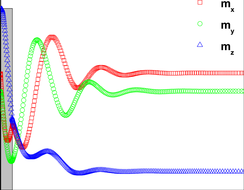
For the case of current flowing along the axis, the spin-orbit field is parallel to the axis. If the applied field is in the plane, the magnetization is also in the plane prior to the application of current pulses. This perpendicular configuration between the spin-orbit field and the magnetization maximizes the precession torque, thus facilitating precessional switching. Using a square-wave shaped current pulse, complete switching can be achieved in about 100 ps, as shown in Fig. 3. The length of the current pulse used in the simulation is 10 ps, which is about one half of the precession period corresponding to the spin-orbit field induced by the current pulse, with the current density = 1.5 1012 A/m2. The applied field is = 0.2 T. Due to the large spin-orbit field, the time needed to realize precessional switching is solely determined by the current density, whose direct consequence is the fact that a very short current pulse can effectively initiate the desired magnetization switching.
In the macrospin simulation, domain nucleation and the consequent domain wall motion, which is crucial for the actual determination of the coercivity, are neglected. Hence the simulated results are only of qualitative significance. However, as can be seen in Fig. 1, the qualitative agreement between the macrospin simulation and the experiment miron11 is satisfactory. Nevertheless, a detailed micromagnetic study, including finite temperature and finite size effects, is needed to gain further insight into the physics involved in the spin-orbit field induced reversible switching of magnetization in perpendicularly magnetized thin films. Experimentally, a thorough investigation of the magnetization dynamics following current excitation in such systems will prove to be important to clarify the role played by the spin-orbit field in manipulating the macroscopic state of magnetization. In Pt/Co/AlOx or similar systems, this can be achieved by time resolved magneto optical Kerr effect, which is already demonstrated to be a powerful technique for the study of magnetization dynamics in thin metallic magnetic films van Kampen02 .
In summary, the spin-orbit field acting on the magnetization, mediated by the Rashba field experienced by itinerant electrons confined in a spatial inversion asymmetric plane, through the s-d exchange coupling, is proposed for the manipulation of magnetization. Perpendicular switching of magnetization in Pt/Co/AlOx nanodots, with in-plane applied field, can be realized using only the spin-orbit field, without the need of any extra fields. This simplifies the explanation for the experimental observation miron11 . Ultrafast switching, on the time scale of 100 ps, is made possible by the large magnitude of the spin-orbit field in systems with large PMA, such as Pt/Co/AlOx. For perspectives, the spin-orbit field, properly tailored, can be used to coherently control spin oscillation and domain wall motion, in conjunction with the more familiar spin transfer torques, thus providing more freedom over the control of magnetization dynamics. The most recent experimental advance on this respect is the enhancement of domain wall velocity in perpendicularly magnetized Pt/Co/AlOx nanowires miron11dw . Stimulated by the impetus from information technology, more advances are to be expected.
Acknowledgements.
D.W. thanks group Physics of Nanostructures (FNA), Eindhoven University of Technology for hospitality. Enlightening discussions with Elena Mure and Sjors Schellekens are acknowledged. Constructive comments on the manuscript from Zengxiu Zhao and Jianmin Yuan are gratefully appreciated.References
- (1) A. Kashuba, Phys. Rev. Lett. 96, 047601 (2006).
- (2) I. Tudosa, C. Stamm, A. B. Kashuba, F. King, H. C. Siegmann, J. Stöhr, G. Ju, B. Lu, and D. Weller, Nature 428, 831 (2004).
- (3) C. H. Back, D. Weller, J. Heidmann, D. Mauri, D. Guarisco, E. L. Garwin, and H. C. Siegmann, Phys. Rev. Lett. 81, 3251 (1998); C. H. Back, R. Allenspach, W. Weber, S. S. P. Parkin, D. Weller, E. L. Garwin, and H. C. Siegmann, Science 285, 864 (1999).
- (4) A. Kirilyuk, A. V. Kimel, and Th. Rasing, Rev. Mod. Phys. 82, 2731 (2010).
- (5) H. Ohno, D. Chiba, F. Matsukura, T. Omiya, E. Abe, T. Dietl, Y. Ohno, and K. Ohtani, Nature 408, 944 (2000).
- (6) L. Berger, Phys. Rev. B 54, 9353 (1996); J. C. Slonczewski, J. Magn. Magn. Mater. 159, L1 (1996).
- (7) Yu. A. Bychkov and E. I. Rashba, J. Exp. Theor. Phys. Lett. 39, 78 (1984).
- (8) A. Manchon, and S. Zhang, Phys. Rev. B 78, 212405 (2008); A. Manchon, and S. Zhang, ibid 79, 094422 (2009); A. Matos-Abiague, and R. L. Rodriguez-Suarez, ibid 80, 094424 (2009); I. Garate, and A. H. MacDonald, ibid 80, 134403 (2009).
- (9) I. M. Miron, K. Garello, G. Gaudin, P.-J. Zermatten, M. V. Costache, S. Auffret, S. Bandiera, B. Rodmacq, A. Schuhl, and P. Gambardella, Nature 476, 189 (2011).
- (10) B. Rodmacq, A. Manchon, C. Ducruet, S. Auffret, and B. Dieny, Phys. Rev. B 79, 024423 (2009).
- (11) I. M. Miron, G. Gaudin, S. Auffret, B. Rodmacq, A. Schuhl, S. Pizzini, J. Vogel, and P. Gambardella, Nature Mater. 9, 230 (2010); P. Gambardella, and I. M. Miron, Phil. Trans. R. Soc. A 369, 3175 (2011).
- (12) L. D. Landau, E. M. Lifshitz, and L. P. Pitaevski, Statistical Physics, Part 2, 3rd ed. (Pergamon, Oxford), 1980; T. L. Gilbert, IEEE Trans. Mag. 40, 3443 (2004).
- (13) = 0.3 is close to the experimenally determined Gilbert damping constant in a similar Pt/Co/AlOx sample. The detailed determination of the intrinsic will be published elsewhere.
- (14) Confusion can arise by simple reference to M. Miron et al. miron11 refer to the equilibrium magnetization without current in their expression, while M specifies the magnetization just prior to the removal of current here. For the sense of switching, the sign of the component of the cross product is of significance. Given that the two expressions, in which M has different meanings, produce the same sign for the component, we make no discrimination between them. They are both proportional to Bso Bapp, if only the component is considered.
- (15) M. van Kampen, C. Jozsa, J. T. Kohlhepp, P. LeClair, L. Lagae, W. J. M. de Jonge, and B. Koopmans, Phys. Rev. Lett. 88, 227201 (2002).
- (16) I. M. Miron, T. Moore, H. Szambolics, L. D. Buda-Prejbeanu, S. Auffret, B. Rodmacq, S. Pizzini, J. Vogel, M. Bonfim, A. Schuhl, and G. Gaudin, Nature Mater. 10, 419 (2011).