Spin wave excitation in magnetic insulators by spin-transfer torque
Abstract
We study the excitation of spin waves in magnetic insulators by the current-induced spin-transfer torque. We predict preferential excitation of surface spin waves induced by an easy-axis surface anisotropy with critical current inversely proportional to the penetration depth and surface anisotropy. The surface modes strongly reduce the critical current and enhance the excitation power of the current-induced magnetization dynamics.
Spintronics is all about manipulation and transport of the spin, the intrinsic angular momentum of the electron Žutić et al. (2004). These two tasks are incompatible, since manipulation requires strong coupling of the spin with the outside world, which perturbs transport over long distances. In normal metals spin can be injected and read out easily, but the spin information is lost over short distances Bass and Pratt (2007). In spin-based interconnects, transporting spins over longer distances is highly desirable Khitun and Wang (2011).
The long-range transport of spin information can be achieved by encoding the information into spin waves that are known to propagate coherently over centimeters Serga et al. (2010). It has been demonstrated in Refs. Kajiwara et al., 2010; Madami et al., 2011; Wang et al., 2011 for the magnetic insulator Yttrium-Iron-Garnet (YIG) that spin waves can be actuated electrically by the spin-transfer torque Slonczewski (1996); Berger (1996) and detected by spin pumping Tserkovnyak et al. (2002) at a distant contact. In the experiment by Kajiwara Kajiwara et al. (2010), Pt was used as spin current injector and detector, making use of the (inverse) spin Hall effect Saitoh et al. (2006). In a m-thick YIG film spin waves were excited by a threshold charge current of A/m2. This value is much less than expected for the bulk excitation that in a linear approximation corresponds to the macrospin mode and is estimated as A/m2, where and are the electron charge and gyromagnetic ratio, respectively, and we used the parameter values in Table 1 for the ferromagnetic resonance frequency , the spin Hall angle of Pt , magnetic damping , and saturation magnetization .
In this Letter, we address this large mismatch between observed and expected critical currents by studying the threshold current and excitation power of current-induced spin wave excitations. We present a possible answer to the conundrum by proving that the threshold current is strongly decreased in the presence of an easy-axis surface anisotropy (EASA). Simultaneously, EASA increases the power of the spin wave excitation by at least two orders of magnitude.
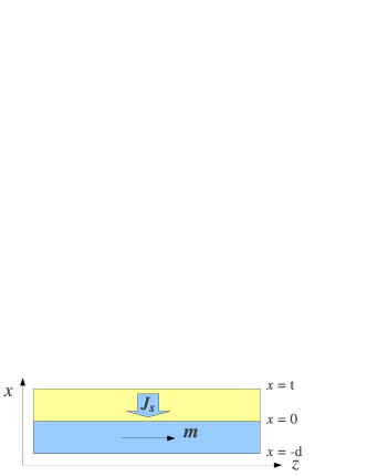
We study a structure as depicted in Fig. 1, where a non-magnetic (N) metallic thin film of thickness is in contact with a ferromagnetic insulator (FI), whose equilibrium magnetization is along the -direction. The spin current injected into the ferromagnetic insulator is polarized transverse to the magnetization . The bulk magnetization is described by the Landau-Lifshitz-Gilbert (LLG) equation:
| (1) |
where includes the external and internal magnetic field, is the exchange constant, and is the dipolar field that satisfies Maxwell’s equations. In the quasistatic approximation, i.e. disregarding retardation in the electromagnetic waves, and . All quantities are position and time dependent. In the absence of pinning, the total torque vanishes at the interface Gurevich and Melkov (1996):
| (2) |
where is the outward normal as seen from the ferromagnet. The first term in Eq. (2) is the surface exchange torque, the second term the torque due to a perpendicular uniaxial surface anisotropy and across the surface, and the last term is the current-induced spin-transfer torque Stiles and Zangwill (2002). We parameterize the surface anisotropy and spin current as wave numbers and . The dipolar fields and are continuous across the interface. Eqs. (1, 2) in combination with Maxwell’s equations describe the low energy magnetization dynamics and can be transformed into a 6th-order differential equation for the scalar potential with De Wames (1970); Hillebrands (1990).
| Parameter | YIG | Unit |
|---|---|---|
| 1/(T s) | ||
| A/m | ||
| GHz | ||
| m2/s | ||
| - | ||
| GHz | ||
| J/m2 |
The method described above extends a previous study by Hillebrands Hillebrands (1990) by including the current-induced spin-transfer torque. We predict the critical conditions under which magnetization dynamics becomes amplified by the current-induced driving torque.
We start with the limiting case of (semi-infinite ferromagnet). After linearization and Fourier transformation in both time and space domains, Eq. (1) reduces to a 4th-order differential equation in . Focusing for simplicity first on the case of vanishing in-plane wave-vector , the scalar potential can be written as: with
| (3) |
and when . Imposing the boundary condition in Eq. (2), up to the first order in :
| (4) |
The solutions of Eq. (4) are the complex eigen-frequencies , whose real part represents the energy and imaginary part the inverse lifetime. To 0th-order in dissipation, i.e. with vanishing bulk damping () and spin current injection (), and using , Eq. (4) simplifies to , which has no non-trivial solution for . The single real solution for obeys such that both are negative imaginary: , i.e. a surface spin wave induced by the easy-axis surface anisotropy. With the criteria Im and to leading order in , Eq. (4) leads to the critical current:
| (5) |
When there is no surface anisotropy (), the critical current diverges because the macrospin mode cannot be excited in a semi-infinite film. Using the parameters given in Table 1 in Eq. (5), we estimate the critical current for exciting the EASA induced surface wave (at ) to be , where is the critical current for bulk excitation in a YIG thin film of thickness m (used below).
EASA pulls down a surface spin wave for the following reason: when , the boundary condition in Eq. (2) requires cancellation between the exchange and surface anisotropy torques: . The exchange torque depends on the magnetization derivative in the normal direction, and can only take one sign in the whole film, and as , therefore . Torque cancellation (for a non-trivial solution) is therefore possible only for . The surface spin wave induced by EASA () for the in-plane magnetized film () discussed in this Letter is analogous to the surface spin waves for the perpendicular magnetized film () induced by easy-plane surface anisotropy () studied before in YIG films Puszkarski (1973); Wigen (1984); Patton (1984); Kalinikos and Slavin (1986); Gurevich and Melkov (1996). For perpendicular magnetization, a different boundary condition: results in a surface wave for .
We now include all ingredients: finite thickness (m), surface anisotropy, intrinsic magnetic damping, spin current injection, exchange coupling, and dipolar fields. We calculate numerically the complex eigen-frequencies as a function of the in-plane wave-vector and the applied spin current at the surface . Im, the effective dissipation, can be either positive (damping) or negative (amplification) when driven by the spin-transfer torque.
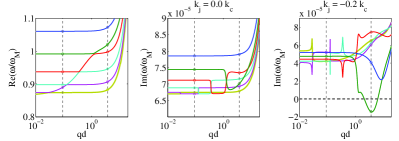
First, we disregard the surface anisotropy: . With the angle between and , the results for are shown in Fig. 2. In the top left panels Re, the magnetostatic surface wave (MSW) is seen to cross the flat bulk bands De Wames (1970). When no spin current is applied (), the dissipative part Im, as shown in the top middle panels. At a spin current that is 20% of that required for bulk excitation: , the dissipative part Im (top right panel) decreases while Re remains unchanged because the spin-transfer torque as magnetic (anti-)damping mainly affects Im. Negative effective dissipation implies spin wave amplification. This happens for the 5th (green) band at , which corresponds to a (chiral) MSW (mixed with bulk modes) formed near the interface (shaded/yellow panel). On the other hand, for (not shown), the magnetostatic surface wave at the opposite surface to vacuum () is only weakly affected by the spin current injection at .
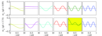
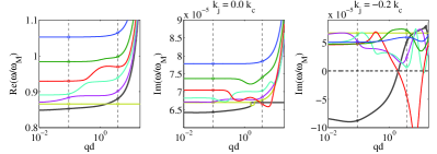
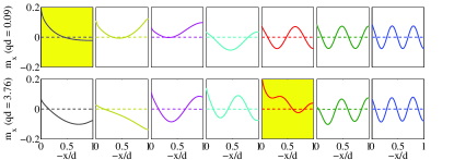
We now turn on EASA: m (or J/m2) at the top surface (). Fig. 3 shows the results for . The changes of Re and Im at are modest (Fig. 2), but an additional band (black) appears, viz. the surface spin wave band induced by EASA. The spin-transfer torque strongly affects this mode because of its strong surface localization Sandweg et al. (2010). As seen in the top right panel, almost the whole band is strongly amplified by a spin current injection of . Inspecting the spin wave profiles at two different values, we observe a surface spin wave near for the black band at small (shaded/yellow panel in the middle row in Fig. 3). At larger , the 1st (black) band loses its surface wave features to the 5th (red) band (see top right panel in Fig. 3). The red band mode starts out as a magnetostatic surface spin wave, but the EASA enhances its surface localization by hybridization with the black mode to become strongly amplified by the spin current at higher . Also in the lower panel of Fig. 3 we observe that the red band has acquired the surface character.
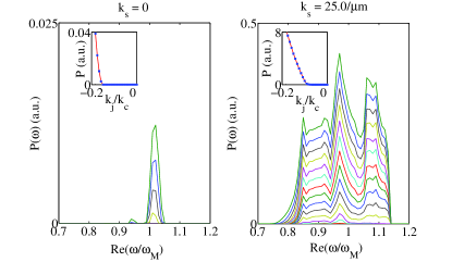
We introduce an approximate power spectrum (Fig. 4) that summarizes all information about the mode-dependent current-induced amplification:
| (6) |
with the band index is the density of states at frequency weighted by its amplification. Without surface anisotropy, only a few modes are excited even at a relatively large current (). However, when /m, the excitation is strongly enhanced by more than two orders of magnitude due to the easily excitable surface spin wave modes. Furthermore, we observe broadband excitation over a much larger range of frequencies. This power spectrum is rather smooth, while the experiments by Kajiwara et al. Kajiwara et al. (2010) show a large number of closely spaced peaks. The latter fine structure is caused by size quantization of spin waves due to the finite lateral extension of the sample that has not been taken into account in our theory since it complicates the calculations without introducing new physics. The envelope of the experimental power spectrum compares favorably with the present model calculations.
The insets in Fig. 4 show the integrated power and allow the following conclusions: 1) the excitation power is enhanced by at least two orders of magnitude by the EASA; 2) the critical current for magnetization dynamics is for m, which agrees very well with the estimates from Eq. (5). This critical current is about one order of magnitude smaller than that for the bulk excitation (), and about half of that for MSW without surface anisotropy (). For m, it corresponds to A/m2 for Mosendz et al. (2010) and A/m2 for Ando et al. (2008); Liu et al. (2011). These values are calculated for a film thickness of m, but should not change much for m corresponding to the experiment Kajiwara et al. (2010), because the excited spin waves are localized at the interface. Compared to the original estimate A/m2, the critical current for a surface spin wave excitation is much closer to the experimental value of A/m2 Kajiwara et al. (2010) (although these experiments report a very inefficient spin wave absorption in contrast to the present model assumption).
According to Eq. (5), critical current (excitation power) would be further reduced (increased) by a larger EASA. Ref. Yen et al., 1979 reports an enhancement of the YIG surface anisotropies for capped as compared to free surfaces. A Pt cover on a YIG surface Kajiwara et al. (2010) may enhance the surface anisotropy as well. As seen from Fig. 3, the surface mode (black band) has group velocity comparable to that of the MSW. The excited surface spin wave therefore propagate and can be used to transmit spin information over long distance at a much lower energy cost than the bulk spin waves.
In conclusion, we predict that an easy-axis surface anisotropy gives rises to a surface spin wave mode, which reduces the threshold current required to excite the spin waves and dramatically increases the excitation power. Multiple spin wave modes can be excited simultaneously at different frequencies and wave-vectors, thereby explaining recent experiments. Surface spin wave excitations could be useful in low-power future spintronics-magnonics hybrid circuits.
This work was supported by the National Natural Science Foundation of China (Grant No. 11004036), the special funds for the Major State Basic Research Project of China (No. 2011CB925601), the FOM foundation, DFG Priority Program SpinCat, and EG-STREP MACALO. J. X. acknowledges the hospitality of the G. B. Group at the Kavli Institute of NanoScience in Delft.
References
- Žutić et al. (2004) I. Žutić, J. Fabian, and S. Das Sarma, Rev. Mod. Phys. 76, 323 (2004).
- Bass and Pratt (2007) J. Bass and W. P. Pratt, J. Phys.: Condensed Matter 19, 183201 (2007).
- Khitun and Wang (2011) A. Khitun and K. L. Wang, Journal of Applied Physics 110, 034306 (2011).
- Serga et al. (2010) A. A. Serga, A. V. Chumak, and B. Hillebrands, J. Phys. D: Applied Physics 43, 264002 (2010).
- Kajiwara et al. (2010) Y. Kajiwara, K. Harii, S. Takahashi, J. Ohe, K. Uchida, M. Mizuguchi, H. Umezawa, H. Kawai, K. Ando, K. Takanashi, et al., Nature 464, 262 (2010).
- Madami et al. (2011) M. Madami, S. Bonetti, G. Consolo, S. Tacchi, G. Carlotti, G. Gubbiotti, F. B. Mancoff, M. A. Yar, and J. Akerman, Nature Nanotechnology 6, 635 (2011).
- Wang et al. (2011) Z. Wang, Y. Sun, M. Wu, V. Tiberkevich, and A. Slavin, Phys. Rev. Lett. 107, 146602 (2011).
- Slonczewski (1996) J. C. Slonczewski, J. Magn. Magn. Mater. 159, L1 (1996).
- Berger (1996) L. Berger, Phys. Rev. B 54, 9353 (1996).
- Tserkovnyak et al. (2002) Y. Tserkovnyak, A. Brataas, and G. E. W. Bauer, Phys. Rev. Lett. 88, 117601 (2002).
- Saitoh et al. (2006) E. Saitoh, M. Ueda, H. Miyajima, and G. Tatara, Applied Physics Letters 88, 182509 (2006).
- Gurevich and Melkov (1996) A. G. Gurevich and G. A. Melkov, Magnetization oscillations and waves (CRC Press, P, 1996).
- Stiles and Zangwill (2002) M. D. Stiles and A. Zangwill, Phys. Rev. B 66, 014407 (2002).
- De Wames (1970) R. E. De Wames, J. Appl. Phys. 41, 987 (1970).
- Hillebrands (1990) B. Hillebrands, Phys. Rev. B 41, 530 (1990).
- Yen et al. (1979) P. Yen, T. S. Stakelon, and P. E. Wigen, Phys. Rev. B 19, 4575 (1979).
- Ramer and Wilts (1976) O. G. Ramer and C. H. Wilts, physica status solidi (b) 73, 443 (1976).
- Puszkarski (1973) H. Puszkarski, IEEE Trans. Magn. 9, 22 (1973).
- Wigen (1984) P. Wigen, Thin Solid Films 114, 135 (1984).
- Patton (1984) C. E. Patton, Phys. Rep. 103, 251 (1984).
- Kalinikos and Slavin (1986) B. A. Kalinikos and A. N. Slavin, J. Phys. C: Sol. Stat. Phys. 19, 7013 (1986).
- Sandweg et al. (2010) C. W. Sandweg, Y. Kajiwara, K. Ando, E. Saitoh, and B. Hillebrands, Applied Physics Letters 97, 252504 (2010).
- Mosendz et al. (2010) O. Mosendz, J. E. Pearson, F. Y. Fradin, G. E. W. Bauer, S. D. Bader, and A. Hoffmann, Phys. Rev. Lett. 104, 046601 (2010).
- Ando et al. (2008) K. Ando, S. Takahashi, K. Harii, K. Sasage, J. Ieda, S. Maekawa, and E. Saitoh, Phys. Rev. Lett. 101, 036601 (2008).
- Liu et al. (2011) L. Liu, T. Moriyama, D. C. Ralph, and R. A. Buhrman, Phys. Rev. Lett. 106, 036601 (2011).