Present address ]Laboratoire de Physique des Lasers, CNRS-UMR7538, Université Paris 13–Institut Galilée, Villetaneuse, France Also at ]ICFO-Institut de Ciencies Fotoniques, Mediterranean Technology Park, 08860 Castelldefels (Barcelona), Spain
Large 2D Coulomb crystals in a radio frequency surface ion trap
Abstract
We designed and operated a surface ion trap, with an ion-substrate distance of 500 m, realized with standard printed-circuit-board techniques. The trap has been loaded with up to a few thousand Sr+ ions in the Coulomb-crystal regime. An analytical model of the pseudo-potential allowed us to determine the parameters that drive the trap into anisotropic regimes in which we obtain large () purely 2D ion Coulomb crystals. These crystals may open a simple and reliable way to experiments on quantum simulations of large 2D systems.
Applications of laser cooled trapped ions are numerous and cover several research fields such as quantum information processing Cirac and Zoller (1995); Leibfried et al. (2003); Häffner, Roos, and Blatt (2008), quantum simulation Porras and Cirac (2004a); Johanning, Varòn, and Wunderlich (2009), cold molecule spectroscopy Willitsch (2010) and metrology Margolis (2010). In the frame of quantum information processing, a large-scale computer architecture has been proposed based on ion shuttling between interaction and memory zones Kielpinski, Monroe, and Wineland (2002). A very practical way to realize such an architecture relies on surface electrode radio-frequency (rf) traps Chiaverini et al. (2005); Seidelin et al. (2006) in which a pseudo-potential well is created above the surface of a substrate by a set of deposited metallic electrodes. The vast majority of the surface traps developed so far Britton et al. (2009); Moehring et al. (2011) are devoted to the trapping and shuttling of short ion strings (1D ion Coulomb crystals). However a peculiar characteristic of the planar geometry, never exploited to date, is its intrinsic anisotropy that can lead to the creation of single-layer 2D ion Coulomb crystals. As suggested by Porras and Cirac Porras and Cirac (2004b), such crystals are well adapted to simulate quantum phase transitions in spin systems. In particular, the control of anisotropy is ideally suited for the study of zigzag transition instabilities directly related to one-dimensional Ising models in a transverse field Shimshoni, Morigi, and Fishman (2011); Bermudez et al. (2011).
In order to create purely 2D laser-cooled ion lattices, three different strategies have been considered so far.
One relies on Penning traps. It allowed for the observation of structural phase transitions Mitchell et al. (1998) and has been more recently used for quantum control experiments Biercuk et al. (2009).
The main disadvantage of this strategy is the difficulty of laser-cooling that has to deal with both magnetron and cyclotron motions Biercuk et al. (2009).
Radio-frequency trap arrays are also a very promising scheme Schmied, Wesenberg, and Leibfried (2009).
The main advantage of this strategy is the possibility to design regular lattice structures that are not imposed by the self-arrangement.
However, the experimental inter-ion distances are, up to now, quite large and do not allow for sufficient ion-ion interaction Clark et al. (2009).
Finally, the surface point Paul trap geometry Pearson et al. (2006), ideally suited to vary the trapping distance from the substrate, can be a promising candidate for quantum simulation Kim et al. (2010). Up to ten ions in a 2D cristalline arrangement have been loaded in this kind of traps realized with printed circuit board technology and operated in a cryogenic environmentClark et al. (2011).
In this paper we present a linear surface rf ion trap based on a standard printed circuit board and we demonstrate the versatility of such a device that allows for the trapping of large crystallized ion ensembles.
Depending on the trap parameters, different crystal shapes can be obtained.
In particular, we demonstrated the formation of single-layer Coulomb crystals containing more than 150 ions.
Previous works have proposed and realized similar devices Brown et al. (2007); Kim et al. (2010) in which the presence of stray fields Brown et al. (2007) or the chosen trap geometry Kim et al. (2010) probably prevented the formation of large Coulomb crystals.
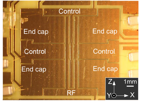
We used a copper FR4 printed circuit board on which strip-lines, forming the ion trap electrodes, were chemically etched and gold-plated (thickness m) using standard commercial procedures. The board material has already proven to be UHV compatible and bakable up to C Rouki, Westerberg, and the CHICSi Development Group (2003). The five wire trap geometry is presented in Fig. 1. The longitudinal confinement is assured by four ”end cap” electrodes. An oscillating potential with typically V and MHz is applied to the rf electrodes. Static voltages in the range -5V to +5V are typically used to drive the central control electrode (), the two lateral control electrodes () and the four endcaps ().
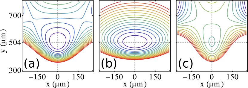
Following reference House, 2008, we performed an analytical calculation of the pseudo-potential associated to this particular trap geometry. The calculation gives us useful information such as the ion motional frequencies as a function of the trap parameters , , and , thus determining the trap axial and transverse anisotropies. The ion distance from the trap surface (504m, imposed by the geometry), the trap depth and the stability parameters are also obtained. Using an approach similar to that described in reference Ozakin and Shaikh (2011), we can also calculate the generalized and stability parameters: , , , and . As an example, Fig. 2 shows three theoretical radial () cross sections of the pseudo-potential obtained with three sets of trapping parameters that produce anisotropic or isotropic potentials.
Sr+ ions are created in the trapping region (typical rate s-1) out of an atomic vapor using a photoionization technique based on two-photon absorption of femtosecond pulses Removille et al. (2009a). The ions are Doppler cooled using the 711 THz optical transition ( nm). To avoid optical pumping into the metastable state we use an additional laser adressing the 275 THz transition ( nm). The laser set-up is very similar to the one described in reference Removille et al., 2009b. The trap is placed in a UHV chamber with an estimated pressure below mbar.
In the experiment, voltages slightly different from the ideal symmetric case have to be applied to the control electrodes in order to position a single trapped ion precisely at the node of the rf electric field. This allows for the reduction of the micro-motion of the ion driven by the rf electric field. In order to optimize these voltages, we used the rf correlation technique Berkeland et al. (1998) that measures the arrival time correlations of single fluorescence photons with the rf cycle. By using purely longitudinal (-propagating) and transverse (propagating at in the plane) cooling beams we were able to compensate for a residual axial micro-motion and the micro-motion along . In order to compensate for the micro-motion along (vertical), we implemented the technique developed by Allcock and co-workers, based on a vertical repumping beam Allcock et al. (2010).
We observe stable trapping and micro-motion compensation voltages which do not vary significantly over a 30 min time-scale. However, optimal compensation voltages are not stable on a day-to-day basis (typical drifts of 70 V/m). With optimized compensation voltages, the single ion lifetime is min, probably limited by the pressure in the vacuum chamber. Single ion fluorescence spectra confirm a linewidth limited by the lifetime of the state ( MHz).
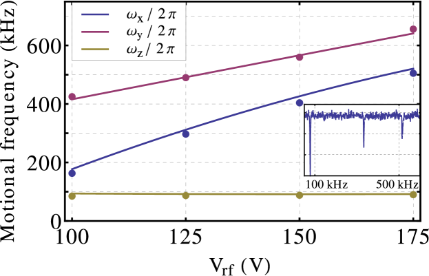
A first test of the pseudo-potential calculation is performed by comparing the experimentally measured motional frequencies with an harmonic fit of the calculated pseudo-potential at the trap center. The motional frequencies are obtained by measuring the single-ion fluorescence intensity as function of the frequency of the excitation voltage (tickle) applied to an endcap electrode (see inset of Fig. 3). The results, shown in Fig. 3, present a very good agreement between calculation and experiment.
Typical fluorescence images of the trapped ions obtained for different trap parameters are shown in Figure 4. In Fig. 4(a) the ions organize themselves as a large three dimensional Coulomb crystal. We observed 3D crystals containing up to a few thousand ions, comparable to the typical numbers obtained in three dimensional macroscopic linear Paul traps Drewsen et al. (1998).
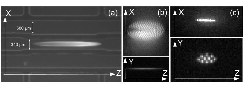
Another and particularly interesting configuration is the single layer Coulomb crystal, demonstrated in Fig. 4(b).
Using an imaging system aligned along the direction, we have actually checked the single layer character of this Coulomb crystal (bottom image).
The non-fluorescing ions visible on the top view of the crystal (left side) are sympathetically-cooled strontium isotopes not addressed by the cooling lasers (only 88Sr+ is laser-cooled in this experiment).
Trap potential calculations allowed us to find a very unusual working point in which the Coulomb crystal forms a single layer perpendicular to the trap surface, as shown in Fig. 4(c). However, contrary to the two previous cases, ions could not be directly loaded using the calculated parameters (see caption of Fig. 2c for this case), propably due to the small value of the trap depth (13 meV).
The trap is actually loaded using parameters close to those used in Fig. 2(c) but with a higher value of , in order to increase the trap depth. Then, is reduced and one can observe the formation of a mono-layer ion crystal perpendicular to the trap surface.With the current trap design we could actually trap up to sixteen ions in this configuration.
As mentioned above, these 2D structures may be exploited for the quantum simulation of two dimensional systems Porras and Cirac (2006). In particular, the ”vertical” arrangement could allow for an easier ion addressing by lasers since the control beams could freely propagate parallel to the trap surface.
In this work, we have demonstrated the versatility offered by an inexpensive, easily fabricated rf surface ion trap based on a printed-circuit board.
We have shown that large Sr+ ion crystals arranged in a 3D structure can be obtained, comparable in size to the crystals used in recent cavity quantum electrodynamics experimentsHerskind et al. (2009).
The same device allowed us to create large ion Coulomb crystals purely bi-dimensional lying parallel to the trap substrate and containing up to 150 ions.
In addition, we also demonstrated 2D Coulomb crystals standing in a plane perpendicular to the trap surface.
This particular geometry allows for an easier individual addressing of ions, especially useful in view of quantum simulation experiments.
This kind of versatile devices will probably become a practical tool for quantum simulation experiments.
We thank M. Apfel and P. Lepert for technical support. We would like to thank D. T. C. Allcock for fruitful discussions and suggestions. We acknowledge financial support by Région Ile-de-France through the SESAME project. B. S. gratefully acknowledges the funding from the Délégation Générale de l’Armement and the French Ministry of Education and Research.
References
- Cirac and Zoller (1995) J. I. Cirac and P. Zoller, Phys. Rev. Lett. 74, 4091 (1995).
- Leibfried et al. (2003) D. Leibfried, R. Blatt, C. Monroe, and D. Wineland, Rev. Mod. Phys. 75, 281 (2003).
- Häffner, Roos, and Blatt (2008) H. Häffner, C. Roos, and R. Blatt, Phys. Rep. 469, 155 (2008).
- Porras and Cirac (2004a) D. Porras and J. I. Cirac, Phys. Rev. Lett. 92, 207901 (2004a).
- Johanning, Varòn, and Wunderlich (2009) M. Johanning, A. F. Varòn, and C. Wunderlich, J. Phys. B: At. Mol. Opt. Phys. 42, 154009 (2009).
- Willitsch (2010) S. Willitsch, Nat. Phys. 6, 240 (2010).
- Margolis (2010) H. S. Margolis, Contemporary Physics 51, 37 (2010).
- Kielpinski, Monroe, and Wineland (2002) D. Kielpinski, C. Monroe, and D. J. Wineland, Nature 417, 709 (2002).
- Chiaverini et al. (2005) J. Chiaverini, R. B. Blakestad, J. Britton, J. D. Jost, C. Langer, D. Leibfried, R. Ozeri, and D. J. Wineland, Quantum Inf. Comput. 5, 419 (2005).
- Seidelin et al. (2006) S. Seidelin, J. Chiaverini, R. Reichle, J. J. Bollinger, D. Leibfried, J. Britton, J. H. Wesenberg, R. B. Blakestad, R. J. Epstein, D. B. Hume, W. M. Itano, J. D. Jost, C. Langer, R. Ozeri, N. Shiga, and D. J. Wineland, Phys. Rev. Lett. 96, 253003 (2006).
- Britton et al. (2009) J. Britton, D. Leibfried, J. A. Beall, R. B. Blakestad, J. H. Wesenberg, and D. J. Wineland, Appl. Phys. Lett. 95, 173102 (2009).
- Moehring et al. (2011) D. L. Moehring, C. Highstrete, D. Stick, K. M. Fortier, R. Haltli, C. Tigges, and M. G. Blain, arXiv:1105.1834v1 [quant-ph] (2011).
- Porras and Cirac (2004b) D. Porras and J. I. Cirac, Phys. Rev. Lett. 93, 263602 (2004b).
- Shimshoni, Morigi, and Fishman (2011) E. Shimshoni, G. Morigi, and S. Fishman, Phys. Rev. Lett. 106, 010401 (2011).
- Bermudez et al. (2011) A. Bermudez, J. Almeida, F. Schmidt-Kaler, A. Retzker, and M. B. Plenio, “arxiv:1108.1024v1 [quant-ph],” (2011).
- Mitchell et al. (1998) T. B. Mitchell, J. J. Bollinger, D. H. E. Dubin, X.-P. Huang, W. M. Itano, and R. H. Baughman, Science 282, 1290 (1998).
- Biercuk et al. (2009) M. J. Biercuk, H. Uys, A. P. VanDevender, N. Shiga, W. M. Itano, and J. J. Bollinger, Quantum Inf. Comput. 9, 920 (2009).
- Schmied, Wesenberg, and Leibfried (2009) R. Schmied, J. H. Wesenberg, and D. Leibfried, Phys. Rev. Lett. 102, 233002 (2009).
- Clark et al. (2009) R. J. Clark, T. Lin, K. R. Brown, and I. L. Chuang, J. Appl. Phys. 105, 013114 (2009).
- Pearson et al. (2006) C. E. Pearson, D. R. Leibrandt, W. S. Bakr, W. J. Mallard, K. R. Brown, and I. L. Chuang, Phys. Rev. A 73, 032307 (2006).
- Kim et al. (2010) T. H. Kim, P. F. Herskind, T. Kim, J. Kim, and I. L. Chuang, Phys. Rev. A 82, 043412 (2010).
- Clark et al. (2011) R. J. Clark, Z. Lin, K. S. Diab, and I. L. Chuang, J. Appl. Phys. 109, 076103 (2011).
- Brown et al. (2007) K. R. Brown, R. J. Clark, J. Labaziewicz, P. Richerme, D. R. Leibrandt, and I. L. Chuang, Phys. Rev. A 75, 015401 (2007).
- Rouki, Westerberg, and the CHICSi Development Group (2003) C. Rouki, L. Westerberg, and the CHICSi Development Group, Physica Scripta 2003, 107 (2003).
- House (2008) M. G. House, Phys. Rev. A 78, 033402 (2008).
- Ozakin and Shaikh (2011) A. Ozakin and F. Shaikh, arXiv:1109.2160v1 [quant-ph] (2011).
- Removille et al. (2009a) S. Removille, R. Dubessy, Q. Glorieux, S. Guibal, T. Coudreau, L. Guidoni, and J.-P. Likforman, Appl. Phys. B 97, 47 (2009a).
- Removille et al. (2009b) S. Removille, R. Dubessy, B. Dubost, Q. Glorieux, T. Coudreau, S. Guibal, J.-P. Likforman, and L. Guidoni, Journal of Physics B: Atomic, Molecular and Optical Physics 42, 154014 (2009b).
- Berkeland et al. (1998) D. J. Berkeland, J. D. Miller, J. C. Bergquist, W. M. Itano, and D. J. Wineland, Journal of Applied Physics 83, 5025 (1998).
- Allcock et al. (2010) D. T. C. Allcock, J. A. Sherman, D. N. Stacey, A. H. Burrell, M. J. Curtis, G. Imreh, N. M. Linke, D. J. Szwer, S. C. Webster, A. M. Steane, and D. M. Lucas, New J. Phys. 12, 053026 (2010).
- Drewsen et al. (1998) M. Drewsen, C. Brodersen, L. Hornekær, J. S. Hangst, and J. P. Schifffer, Phys. Rev. Lett. 81, 2878 (1998).
- Porras and Cirac (2006) D. Porras and J. I. Cirac, Phys. Rev. Lett. 96, 250501 (2006).
- Herskind et al. (2009) P. F. Herskind, A. Dantan, J. P. Marler, M. Albert, and M. Drewsen, Nat. Phys. 5, 494 (2009).