Frequency domain studies of current-induced magnetization dynamics in single magnetic-layer nanopillars
Abstract
Spin transfer torque-induced high-frequency dynamics of single thin cobalt-layer nanopillars of circular and elliptical shape have been observed directly. Two types of precessional modes can be identified as a function of magnetic field perpendicular to the layer plane, excited for negative current polarity only. They are assigned to vortex-core and transverse spin-wave excitations, which corroborate recent model predictions. The observed narrow linewidth of 4 MHz at room temperature indicates the high coherence of the magnetic excitations.
pacs:
72.25.Ba, 72.25.Mk, 75.30.DsAngular momentum conservation of the electron spin is in essence the basis of spintronics. The spin angular momentum can be transferred onto the magnetization of a ferromagnet (FM), thus giving rise to so-called spin transfer torque (STT). This has been predicted theoretically and explored experimentally for magnetic nanostructures Slonczewski (1996); Berger (1996); PRL80_Tsoi1998_ExcitationofaMagneticMultilayerbyanElectricCurrent ; PRL84_Katine2000_Current-DrivenMagnetizationReversalandSpin-WaveExcitationsinCoCuCoPillars ; Stiles and Zangwill (2002); N425_Kiselev2003_MicrowaveOscillationsofaNanomagnetDrivenbyaSpin-PolarizedCurrent ; NM3_Lee2004_ExcitationsofIncoherentSpin-WavesDuetoSpin-TransferTorque ; S307_Krivorotov2005_Time-DomainMeasurementsofNanomagnetDynamicsDrivenbySpin-TransferTorques ; Kaka_Nature to switch their magnetization, triggering also magnetization dynamics concomitant with emission of microwave radiation. Mainly double magnetic layer nanostructures (FM/NM/FM) of an FM layer polarizing the electron current and an STT switching layer with an intervening nonmagnetic metal (NM) spacer layer have been investigated, also regarding spin torque oscillators Kaka_Nature ; NP3_Pribiag2007_MagneticVortexOscillatorDrivenbyDCSpin-polarizedCurrent . However, recent experimental observations Ji et al. (2003); PRL93_Ozyilmaz2004_Current-InducedExcitationsinSingleCobaltFerromagneticLayerNanopillars ; Özyilmaz and Kent (2006) and theoretical studies Polianski and Brouwer (2004); Stiles et al. (2004); Adam et al. (2006); Hoefer et al. (2008) suggest that even an unpolarized current passing perpendicular to a single thin FM layer can cause an STT on this FM layer. Spin filtering effects by a single FM layer contacted by NM leads creates spin accumulation of opposite sign at both interfaces. The associated torques of opposite sign may cancel each other. Asymmetric leads, however, break the symmetry of the single magnetic layer (NM/FM/NM) structure and yield a net STT on the magnetization for one current polarity only Polianski and Brouwer (2004). Requirement is that the spins diffuse in the NM leads along the interfaces and that the FM magnetization is nonuniform or inhomogeneous. This mechanism was not included in the Slonczewski model Slonczewski (1996). The direction of the torque is to align the local magnetization with the direction of the accumulated spins.
For single, extended FM layers studied by means of point contacts the predicted spin-torque induced excitations depend on competing Oersted and external magnetic fields Hoefer et al. (2008). For thick FM layers the formation of a nanodomain underneath the nanocontact obtains a more intricate experiment Ji et al. (2003); PRL93_Chen2004_Current-DrivenSwitchinginaSingleExchange-BiasedFerromagneticLayer . For single FM layers laterally confined to a nanopillar, current-induced excitations of spin waves transverse to the current flow direction have been predicted Polianski and Brouwer (2004); Adam et al. (2006). Assuming additionally a nonuniform magnetization normal to the layer plane for the net spin torque a lowest mode is found, which is nonuniform both parallel and perpendicular to the layer plane Stiles et al. (2004); McMichael and Stiles (2005). First experimental observations of current induced resistance changes of single nanosized FM layers have been reported PRL93_Ozyilmaz2004_Current-InducedExcitationsinSingleCobaltFerromagneticLayerNanopillars ; Özyilmaz and Kent (2006). Only by analogy to magnetic double layer structures have they been assigned to the onset of possible magnetic excitations. However, a direct experimental proof of the high frequency magnetization dynamics and identification of the excited magnetic modes is still missing.
Using frequency domain spectroscopy, we observe for a single nano-confined thin FM layer directly two types of characteristic eigenmodes triggered by a dc current perpendicular to the layer plane. These modes are assigned to vortex-core and transverse spin-wave excitations deduced from their characteristic frequency vs current or vs field dependences. This is in contrast to previous static studies of differential-resistance vs current , which help only in identifying mode onsets. Asymmetries are observed with respect to current polarity for spin excitations and field polarity for microwave emission power as well as mode overtones. The small linewidth of only 4 MHz for Co at room temperature (RT) proves the high coherence due to nonlocal STT effects. Our results confirm recent qualitative predictions of current-induced spin-wave excitations in single FM layers. Moreover, they pave the way for technological applications due to relaxed constraints on magnetization uniformity and elimination of retroactions in dynamics between switching and polarizing, fixed magnetic layers N425_Kiselev2003_MicrowaveOscillationsofaNanomagnetDrivenbyaSpin-PolarizedCurrent .
The samples have been fabricated using a focused ion-beam assisted nanostencil mask technique JoAP101_Ozyilmaz2007_Focused-Ion-BeamMillingBasedNanostencilMaskFabricationforSpinTransferTorqueStudies . The thin layer stack of 10 nm Cu/15 nm Co/150 nm Cu (Fig. 1(a)) is deposited by means of molecular beam epitaxy in prefabricated undercut templates on top of a Pt bottom electrode. The latter acts additionally as a spin sink ensuring the asymmetry of the electrical leads. The investigated nanopillars have either circular (diameter nm) or elliptical ( nm2) cross-sections. The device is connected to microwave probes and a dc current flows through a bias-tee, along with a A ac current. The high frequency components of the resistance changes due to magnetization dynamics are analyzed using a spectrum analyzer with a bandwidth of the circuit of GHz. The electron flow from the thick to the thin Cu layer lead, known to cause a destabilizing or switching torque, is defined as the negative current polarity. All measurements are performed at RT and for each power spectrum presented the current independent background noise has been subtracted.
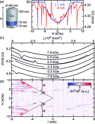
The anisotropic magnetoresistance (AMR) of a single magnetic layer nanopillar at almost zero dc bias (0.1 mA) and a magnetic field oriented perpendicular to the sample plane (ptp) is shown in Fig. 1(b). Starting from in a low resistance state saturates in a high resistance state at magnetic fields above 5 kOe, indicating a ptp magnetization alignment, parallel to . This field is reduced from the out-of-plane demagnetization field of Co for the unpatterned film, because of the Co layer confined in the nanopillar yielding an out-of-plane demagnetization factor of 6.72 in cgs units (compared to of the unpatternded film). This was calculated from 6-fold integration of dipole-dipole interaction for the given geometry Lee . For high negative current values of mA ( A/cm2) there are resistance anomalies superimposed on this AMR curve in the form of pronounced dips and peaks, which are absent for positive current values (not shown). Typical changes as a function of are shown in Fig. 1 (c) for different of both polarities. To better visualize the current and field dependence of these resistance curves and for a better distinction from the parabolic background (Fig. 1(b,c)) we plot in Fig. 1(d) the second derivative (color coded) as a function of and applied ptp--field. For no pronounced dips and peaks are observed, consistent with predictions Polianski and Brouwer (2004). For and increasing absolute field values we first observe peaks () in , which represent an increase in junction resistance. These features shift with increasing fields to higher negative current values. The opposite dependence is observed for the dips (), appearing at slightly higher absolute magnetic fields. The dips indicate a decrease in junction resistance, which has been theoretically attributed to spin-wave excitations Polianski and Brouwer (2004); Adam et al. (2006). As shown in Fig 1(c) there exists an asymmetry in the amplitude and current value of peaks and dips with regard to the field polarity. Hysteretic switching effects is observed in a small range near kOe. Similar results are present in elliptically shaped nanopillars (see Fig. 3(d)), consistent with recent experimental work PRL93_Ozyilmaz2004_Current-InducedExcitationsinSingleCobaltFerromagneticLayerNanopillars ; Özyilmaz and Kent (2006).
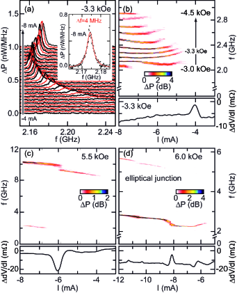
First we consider the frequency spectrum of the circular sample for kOe and currents from mA to mA (Fig. 2(a)). At mA, slightly beyond the peak observed in (Fig. 2(b), bottom), we begin to resolve microwave emission at GHz. denotes that the parabolic background has been subtracted. As the negative current is increased in magnitude the initial signal grows in amplitude and shifts to smaller frequencies until mA, beyond which the excitation frequency increases again. The very narrow linewidth of 4 MHz for Co at RT (inset Fig. 2(a)) demonstrates the unexpected high coherence of the observed mode. As one can see in Fig. 2(b) the above described ”low” frequency (”low-f”) mode is representative for the peak regime (compare Fig. 1(d)). The onset of microwave emission in Fig. 2(b) shifts to higher negative current values for increasing negative fields consistent with the shift of the peak position in the vs diagram (Fig. 1(d)). Please note that the output power does not directly scale with the peak amplitude in the vs curves (Fig. 1(c)), since we observe lower microwave power at (not shown) where the peak amplitudes are larger.
Besides the ”low-” mode an additional high frequency mode is observed (Fig. 2(c)). The onset of the ”high-” mode is related to a decrease in vs near -4 mA (bottom panel of Fig. 2(c)) and does not correspond to a higher harmonics of the ”low-” mode. The frequency of this high- mode with a typical linewidth of MHz near mA increases linearly with increasing negative current. The microwave signal exhibits a frequency jump near mA linked to a strong dip in the differential resistance. The jump is attributed to transitions between different excited spin-wave modes as theoretically predicted Stiles et al. (2004). The bistability of both low- and high- mode vanishes for further increasing fields (Fig. 3(a)). In comparison to single mode excitations the modes in the bistability regime have broader linewidths of 10 MHz and 90 MHz for the low- and high- mode, respectively, at mA and kOe. This indicates a decrease in temporal coherence PRB76_Krivorotov2007_Large-amplitudeCoherentSpinWavesExcitedbySpin-polarizedCurrentinNanoscaleSpinValves . of nanopillars with elliptical cross-section in Fig. 2(d), bottom, shows alternating dips and peaks. Surprisingly, only one narrow mode together with its first harmonic is observable. The assignment to peaks and dips is not as straightforward and more complex.
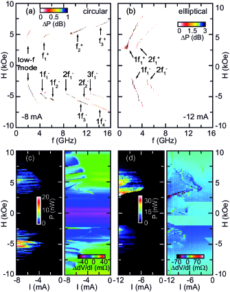
To further explore the diversity of the observed modes we discuss the field dependence of the emitted microwave power for . For the circular sample (Fig. 3(a)) multiple mode frequencies are observed for both field polarities. Besides the low- mode these are the high- modes , , for and for together with their higher harmonics , . For a given mode the frequency corresponds to an eigenmode of the Co nanodisc and increases nearly linearly with the applied field as expected from the theoretical models Adam et al. (2006); McMichael and Stiles (2005). A field asymmetry concerns the measured frequencies and , which show also jumps.
For the elliptically shaped nanopillar the field dependence of the mode frequencies is less complex, because only one mode together with its first harmonic is excited (Fig. 3(b)). Again a strong asymmetry appears concerning the field polarity, since and frequency jumps appear for negative fields only. Hence the asymmetry in the transport measurements ( vs in Fig. 3(d), right panel) reflects that of the observed frequency behavior as well as that of the integrated microwave power (Fig. 3 (d), left panel). The correlation of the resistance changes (Fig. 3 (c,d), right panels) to the microwave power output (Fig. 3 (c,d), left panels) is clearly visible, but there is still a lack in understanding the link to the quantitative magnitude of the power.
Micromagnetic calculations of excited normal modes for circular and elliptical nanoelements exhibit low frequency uniform precession modes and higher frequency modes of different (even/odd) symmetries McMichael and Stiles (2005). For elliptical shapes the many symmetry modes are merging into fewer ones as calculated from spin-wave dispersion for discrete wave vectors. This may explain the fewer high frequency modes of elliptical compared to circular elements (Fig. 3a,b), besides the lower elliptical symmetry. A more rigorous treatment has to analyze for the lowest critical current of modes being driven unstable. Quantitative predictions have failed so far because of the difficulty in combining spin diffusion with micromagnetic simulations. It has been argued that inhomogeneities in the magnetization transverse to the current flow direction reduce the resistance of a single magnetic layer due to a mixing of spin channels. As the high- mode of circular pillars is linked to the dips in the differential resistance one could attribute this mode to transverse spin waves, which are expected in single magnetic layer nanopillar devices Polianski and Brouwer (2004); Adam et al. (2006). In order to compare our measurements for the circular nanopillar with calculated eigenfrequencies of a circular Co nanoelement McMichael and Stiles (2005), we extrapolate the high frequency mode (Fig. 3(a)) to higher fields. The extrapolated value of about 40 GHz at 20 kOe agrees well with the calculated value for transverse spin waves.
The peaks in , equivalent to an increase in junction resistance, may be explained by inhomogeneities in the magnetization normal to the thin film plane, i.e. due to a GMR-like effect. These peaks are most pronounced at relatively low fields ( kOe) for the circular pillar (Fig. 2(b)). A circular pillar with diameter of d nm and a Co thickness of 15 nm, together with the current induced Oersted field and the external ptp-H field, enables the formation of a vortex inside the FM layer S298_Wachowiak2002_DirectObservationofInternalSpinStructureofMagneticVortexCores ; S289_Shinjo2000_MagneticVortexCoreObservationinCircularDotsofPermalloy ; PRL94_Ding2005_MagneticBistabilityofCoNanodots ; PRB73_Urazhdin2006_EffectsofCurrentontheMagneticStatesofPermalloyNanodiscs . The lowest excitation mode for a vortex is the gyroscopic precession of the core with frequencies of the order of f GHz S304_Choe2004_VortexCore-DrivenMagnetizationDynamics , comparable to the mode frequency in Fig. 2(b). It has been shown NP3_Pribiag2007_MagneticVortexOscillatorDrivenbyDCSpin-polarizedCurrent that the vortex core dynamics can be excited by spin-polarized currents. In that case micromagnetic simulations demonstrate a vortex-core precession with unequal trajectories on either side of the FM layer, resulting from inhomogeneities in the magnetization perpendicular to plane. Therefore we suppose the low- mode to be a vortex-core like precession. The more complex resistance changes, observed in Fig. 2(d), bottom, may give evidence that the mode near 3 GHz and its overtone originate from multivortex-state precessions Okuno et al. (2004).
In conclusion, we have observed current-induced triggering of highly coherent spin waves in single Co layer nanopillars at RT by an unpolarized current for out-of-plane magnetic fields. Dynamical modes at different frequencies are found and a possible correlation to transverse spin waves and vortex-core dynamics is discussed for circular and elliptical cross-sections of the nanopillars. These experimental data require more detailed simulations which we hope to have stimulated by this work.
We acknowledge useful discussion with K.J. Lee. This work was supported by DFG through SPP 1133.
References
- Slonczewski (1996) J. C. Slonczewski, J. Magn. Magn. Mater. 159, L1 (1996).
- Berger (1996) L. Berger, Phys. Rev. B 54, 9353 (1996).
- (3) M. Tsoi et al., Phys. Rev. Lett. 80, 4281 (1998).
- (4) J. A. Katine et al., Phys. Rev. Lett. 84, 3149 (2000).
- Stiles and Zangwill (2002) M. D. Stiles and A. Zangwill, Phys. Rev. B 66, 014407 (2002).
- (6) S. I. Kiselev et al., Nature 425, 380 (2003).
- (7) K.-J. Lee et al., Nature Mat. 3, 877 (2004).
- (8) I. N. Krivorotov et al., Science 307, 228 (2005).
- (9) S. Kaka et al., Nature 437, 389 (2005).
- (10) V. S. Pribiag et al., Nature Phys. 3, 498 (2007).
- Ji et al. (2003) Y. Ji, C. L. Chien, and M. D. Stiles, Phys. Rev. Lett. 90, 106601 (2003).
- (12) B. Özyilmaz et al., Phys. Rev. Lett. 93, 176604 (2004).
- Özyilmaz and Kent (2006) B. Özyilmaz and A. D. Kent, Appl. Phys. Lett. 88, 162506 (2006).
- Polianski and Brouwer (2004) M. L. Polianski and P. W. Brouwer, Phys. Rev. Lett. 92, 026602 (2004).
- Stiles et al. (2004) M. D. Stiles, J. Xiao, and A. Zangwill, Phys. Rev. B 69, 054408 (2004).
- Adam et al. (2006) S. Adam, M. L. Polianski, and P. W. Brouwer, Phys. Rev. B 73, 024425 (2006).
- Hoefer et al. (2008) M. A. Hoefer, T. J. Silva, and M. D. Stiles, Phys. Rev. B 77, 144401 (2008).
- (18) T. Y. Chen et al., Phys. Rev. Lett. 93, 026601 (2004).
- McMichael and Stiles (2005) R. D. McMichael and M. D. Stiles, J. Appl. Phys. 97, 10J901 (2005).
- (20) B. Özyilmaz et al., J. Appl. Phys. 101, 063920 (2007).
- (21) K.-J. Lee, private communication.
- (22) I. N. Krivorotov et al., Phys. Rev. B 76, 024418 (2007).
- (23) A. Wachowiak et al., Science 298, 577 (2002).
- (24) T. Shinjo et al., Science 289, 930 (2000).
- (25) H. F. Ding et al., Phys. Rev. Lett. 94, 157202 (2005).
- (26) S. Urazhdin et al., Phys. Rev. B 73, 054416 (2006).
- (27) S.-B. Choe et al., Science 304, 420 (2004).
- Okuno et al. (2004) T. Okuno, K. Mibu, and T. Shinjo, J. Appl. Phys. 95, 3612 (2004).