Symbol-Index-Feedback Polar Coding Schemes for Low-Complexity Devices
Abstract
Recently, a new class of error-control codes, the polar codes, have attracted much attention. The polar codes are the first known class of capacity-achieving codes for many important communication channels. In addition, polar codes have low-complexity encoding algorithms. Therefore, these codes are favorable choices for low-complexity devices, for example, in ubiquitous computing and sensor networks. However, the polar codes fall short in terms of finite-length error probabilities, compared with the state-of-the-art codes, such as the low-density parity-check codes. In this paper, in order to improve the error probabilities of the polar codes, we propose novel interactive coding schemes using receiver feedback based on polar codes. The proposed coding schemes have very low computational complexities at the transmitter side. By experimental results, we show that the proposed coding schemes achieve significantly lower error probabilities.
I Introduction
Recently, a new type of error control codes polar codes have attracted much attention. Recently invented in 2009 [1], these codes are the first known class of error control codes, which achieve the Shannon channel capacity for binary input symmetric output channels. In addition, the encoding algorithms of polar codes have very low complexities compared with these of Turbo codes and low-density parity-check codes. Thus, these codes are attractive choices for low-complexity and power-constrained communication devices. However, for finite-length performance, the polar codes still fall short in terms of error probabilities compared with the state-of-the-art error control codes, such as, the low-density parity-check codes. Therefore, it is desirable that the error probabilities of the polar codes can be improved.
It is well-known in the information theory that receiver feedback can be used to improve the performance of channel coding. It is shown by Schalkwijk and Kailath that if the feedback channel is noiseless, then doubly exponential error probabilities can be achieved [2]. It is shown by Wyner that if a peak energy constraint is imposed, then only singly exponential error probabilities are possible [3]. Burnashev shows some coding schemes using noiseless feedback and an upper bound on the error probability exponent [4]. The Burnashev bound can be achieved by a scheme of Yamamoto and Itoh [5]. Forney proposes a scheme based on decoding reliability estimation and erasure feedback, which can achieve error probability exponents strictly larger than the sphere-packing bounds [6]. The above schemes by Burnashev, Yamamoto-Itoh, and Forney are all based on block-wise feedback. There also exist symbol-wise feedback schemes, such as in [7] [8] etc.
From these previous discussions, many important theoretical results on achievable rates, error probabilities, reliable functions have been obtained. However, there exist very few practical low-complexity coding schemes using receiver feedback to achieve these performance improvements. The existing symbol-wise feedback schemes usually have high computational complexities. Some practical Yamamoto-Ito type feedback schemes are discussed in [9]. The Yamamoto-Ito schemes are based on block-wise feedback and must be built upon some baseline block codes, which can provide reasonably reliable decoding results. The schemes in [9] use the Turbo and low-density parity-check codes as the baseline block codes.
In this paper, we propose novel low-complexity coding schemes based on polar codes using receiver feedback. We call these coding schemes, symbol-index-feedback polar coding schemes. In the proposed coding schemes, the data transmission process is mainly an interactive process between the transmitter and the receiver. During each time slot, the receiver determines the index for the next transmit symbol and sends the index using the feedback channel. After receiving the symbol index from the feedback channel, the transmitter transmits the corresponding symbol to the receiver using the forward channel. There exist at least two variations of our proposed coding schemes, one fixed-length type and one variable-length type. The differences are mainly on the stop rules for the above interactive process. The next transmit symbol index should be determined based on decoding reliability at the receiver side. We propose a virtual equivalent channel approach for determining the next transmit symbol index.
By experimental results, we show that the proposed coding schemes achieve significantly lower error-probabilities compared with the conventional polar codes. The symbol-index-feedback schemes can be used as standalong symbol-wise feedback schemes. These schemes can also be combined with the block-wise feedback schemes, such as the Yamamoto-Ito type schemes. In the latter case, the symbol-index-feedback schemes are used as baseline blocks codes. In both the two cases, the proposed coding schemes have very low computational complexities at the transmitter side.
The proposed coding schemes in this paper are attractive choices for many low complexity devices in ubiquitous computing and sensor network applications. In these applications, the transmitters and receivers have rather different power and complexity constraints. The transmitters, such as Radio Frequency IDentification (RFID) tags and sensor nodes, usually have limited power supplies. For example, these devices are usually battery based. The RFID tags and sensor nodes must also have low-costs and low-complexities. On the other hand, the receivers, such as the RFID readers and data collection centers, usually are much less restricted in terms of costs and power. There usually also exist reverse communication links from the receiver to the transmitter, which can be used as feedback channels in the proposed symbol-index-feedback polar coding schemes.
The rest of this paper is organized as follows. In Section II, we provide a basic review of the polar codes. In Section III, we propose the virtual equivalent channel method to determine decoding reliability. The decoding reliability estimation may be used in the proposed coding schemes to determine the next transmit symbol. In Section IV, we show the proposed symbol-index-feedback polar coding schemes. Some numerical results and discussions are shown in Section V. The numerical results show that our schemes achieve significantly lower error probabilities compared with the conventional polar codes. The concluding remarks are present in Section VI.
We will use the following notation throughout this paper. We use to denote a sequence of symbols . We use to denote the binary XOR operator. For a binary input channel , , , the Bhattacharyya parameter is defined as
| (1) |
II Polar Codes
In this section, we provide a brief review of polar codes. Polar codes are a class of linear block codes with block length , where are certain positive integers. Each polar code is associated with an index set . Let the cardinality of the set . The rate of the polar code is .
The encoding process of a polar code includes two steps. In the first step, the encoding method maps the binary string of the transmit message into one binary string . Each bit in is written into one of the with . For , . In the second step of encoding, the binary string is input into a so called channel. The output of the channel is an bit binary sequence , which is the encoded codeword.
The channels are recursively defined. For a channel, if the input is one binary sequence , then the output of the channel is the binary sequence . For one channel , the channel first divides the input into a binary odd-index-component substring and a binary even-index-component substring . The even-index-component substring is then added into the odd-index-component substring. That is, two sequences are generated,
The sequences and are input into two independent channels. Let and denote the outputs of the two independent channels respectively. The output of the channel is the concatenated sequence of and . A block diagram of the channel is shown in Fig. 1.
-
Example
Suppose that we have a polar code with block length . Suppose that . Let the transmit message . Then in the encoding process, is mapped into a binary string . In the channel, is decomposed into and . The outputs of the two independent channels are , and . The codeword .

The major decoding method of polar codes is the decision feedback decoding algorithm. The decoding algorithm sequentially estimates the bits in the string , starting from the first bit. If , then the decoding algorithm always decodes . For each , the algorithm makes the decoding decision based on some calculated probabilities. Let denote the channel observations. The bit is decoded into , if
| (2) |
Otherwise, The bit is decoded into . The sequence can be taken to be the already decoded bits in the probability calculation.
In [1], the reliability of the decoding is analyzed by using the Bhattacharyya parameters. Essentially for each , the bit-wise estimation can be related to a channel
For each such channel, we may define a Bhattacharyya parameter
| (3) |
where, the summation is over all the realizations of the random variables .
It is shown in [1] that the Bhattacharyya parameters can be recursively upper bounded. Note that and are the inputs of some channels similarly as . Therefore, similar channels and corresponding Bhattacharyya parameters can be defined.
In [1], it is shown that for even-indexed ,
| (4) |
and for odd-indexed ,
| (5) |
Therefore, some upper bounds of can be recursively calculated. This recursive process starts with upper bounding the Bhattacharyya parameters for the channels based on , where is the Bhattacharyya parameter for the channel . The Bhattacharyya parameters are important, because is an important indicator of the decoding reliability. In fact, it is shown in [1] that is an upper bound of the block error probability.
In the sequel, we may abuse the notation and use to denote the above recursively calculated upper bounds of the Bhattacharyya parameters without introducing ambiguity. Because the exact values of will not be calculated in this paper. Whenever denotes an actual number as in an algorithm, it denotes the above recursively calculated upper bound.
III Virtual Equivalent Channel Method for Decoding Reliability Estimation
In this section, we present the proposed method for determining the decoding reliability for each message bit based on the already received channel observations. That is, if the transmit message is decoded based on the already received channel observations, then how reliable the decoding result is for each message bit. Such decoding reliability information may be used for adapting the proposed coding scheme. For example, the future transmit symbol is selected, so that the decoding reliability can be most significantly improved. In this paper, we focus our discussions on the Binary Input Additive White Gaussian Noise (BIAWGN) channels. However, our methods can be generalized to other channel models as well.
In the sequel, we assume that the feed-forward channel is BIAWGN, where , is the transmitted signal, is the additive noise with variance and is the received channel observation. We assume that a BPSK modulation is used. That is, if , then the signal is transmitted, and if , then the signal is transmitted.
The proposed decoding reliability estimation method is based on a virtual equivalent channel approach. The key observation is that, given the amplitude of the channel observation , the channel between and can be considered as a binary symmetric channel, such that
| (6) |
where is a normalization constant. The equivalent binary symmetric channel is shown in Fig. 2, where the channel parameter
| (7) |

In other words, we consider the probability space of . We form a filtration for this probability space, where the first -algebra is generated by the random events , and the second -algebra contains all the information about and . Conditioned on the first -algebra and the amplitude of the received channel observation, we may redefine the Bhattacharyya parameter of the channel between and as the Bhattacharyya parameter of the binary symmetric channel in Fig. 2,
| (8) |
This Bhattacharyya parameter measures the decoding reliability for the symbol with the information of . Clearly, the total reliability measure can also be updated with the updated .
In the case that one symbol is transmitted through the feed-forward channel times and channel observations have been observed, we may consider a virtual equivalent channel, where the input is binary and the output alphabet consists of symbols with the form , . The corresponding Bhattacharyya parameter is
| (9) |
There also exist other equivalent channel models for calculating the Bhattacharyya parameter .
IV Polar Coding Scheme with Feedback
In this section, we present the proposed low-complexity polar coding schemes using receiver feedback. We call such schemes as the symbol-index-feedback schemes. We discuss two versions of the proposed schemes. The first version is called fixed-length symbol-index-feedback scheme. For each block of transmit information bits, the proposed coding scheme includes three stages.
Initial Stage: encode the transmit information bits using a conventional polar code with blocklength and rate . Transmit a predefined number of bits of the codeword using the feed-forward channel.
Interactive Stage: during each time slot, the receiver sends one request of symbol using the feedback channel. The request of symbol message contains the requested symbol index , . After receiving the index of the request symbol, the transmitter sends the request bit through the feed-forward channel. After receiving the transmit bit, the receiver updates the Bhattacharyya parameter and according to the rules in Section III. The coding scheme may repeat the above interactive process for a pre-designed fixed number of time, and then goes to the stop stage. The symbol index should be chosen, so that the decoding reliability can be significantly improved. In this paper, we propose an approach of determining , such that
| (10) |
That is, descends most significantly, if decreases.
Stop Stage: a polar decoding algorithm, such as the decision feedback decoding algorithm, is used. The scheme then outputs the decoding results.
The second version is called variable-length symbol-index-feedback scheme using error-detection. For each block of transmit information bits, the coding scheme includes three stages.
Initial Stage: first encode the transmit information bits using one conventional error-detection code into a codeword with length . Encode the error-detection codeword bits using one conventional polar code with blocklength and rate . Transmit a predefined number of bits of the polar codeword , using the feed-forward channel.
Interactive Stage: similarly as in the fixed-length scheme. After the fixed number of bits are transmitted, the coding scheme goes to the following stop stage.
Stop Stage: a polar decoding algorithm, such as the decision feedback decoding algorithm, is used. The scheme then outputs the decoding results, if no decoding error is detected by the error-detection code. Otherwise, the scheme returns to the interactive stage.
V Numerical Results and Discussions
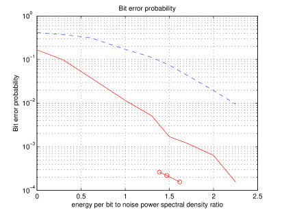
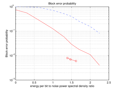
In this section, we present simulation results for the proposed symbol-index-feedback polar coding schemes. In Fig. 3, we show the bit error probabilities of the symbol-index-feedback schemes, and the conventional polar codes. The solid line shows the bit error probabilities of the fixed-length symbol-index-feedback polar coding scheme. The solid line with circles shows the bit error probabilities of the variable-length symbol-index-feedback polar coding scheme. The dashed line shows the bit error probabilities for the conventional polar code without using receiver feedback. The block error probabilities of the above three coding schemes are shown in Fig. 4, where the block error probabilities of the fixed-length symbol-index-feedback scheme, variable-length symbol-index-feedback scheme, and the conventional polar code are shown by the solid line, solid line with circles, and dashed line respectively. The -axis of the two figures shows the , the energy per bit to noise power spectral density ratio in dB as defined in [10, Sec. 4.2]. All the above coding schemes use one baseline polar code with blocklength bits and rate . The channel is a AWGN channel with noise variance . Each codeword bit is transmitted with power . The numbers of codeword bit transmission (or average numbers) are determined by the .
From the above figures and other simulation results that we have obtained for many different cases of block lengths, coding rates etc, we conclude that the symbol-index-feedback polar coding schemes achieve significantly lower bit and block error probabilities compared with the conventional polar codes. The performance improvement is due to the fact that in the proposed schemes, the data transmission processes are adapted to the already received channel observations. The receivers are able to determine the part of the transmit bits that can not be reliably decoded, and request the codeword bits that can increase the decoding reliability most significantly being transmitted. The data transmission processes are therefore steered to arrive at reliable decoding results.
The variable-length version of the proposed schemes outperforms the fixed-length version, This performance improvement is due to flexible energy allocation between transmit bit blocks. The variable-length scheme allocates less power for the blocks that can be reliably decoded. The saved power may be used for some other blocks, where the noise is atypical and decoding errors are more likely. In fact, similar phenomenon that variable-length schemes have better performance have been observed in the previous research, see for example, [11], [12], [13] etc.
The proposed coding schemes are different from many previous coding schemes using feedback. In the proposed schemes, the requested symbol indexes are feedback. While, many previous coding schemes transmit the quantized channel observations back to the transmitter. One main advantage of the proposed coding schemes is that almost all computational complexities are at the receiver side. The proposed coding schemes are favorable choices for the communication scenarios, where the transmitters are power and complexity constrained. Such low power and complexity devices may include many embedded devices in ubiquitous computing, RFIDs, embedded sensors in sensor networks etc.
VI Conclusion
In this paper, we propose novel error-control coding schemes using receiver feedback based on polar codes. Two variations of the proposed symbol-index-feedback schemes are discussed, including one fixed-length scheme and one variable-length scheme. By simulation results, we show that the proposed coding schemes achieve significantly lower error probabilities compared with the conventional polar codes. The variable-length scheme outperforms the fixed-length scheme in terms of error probabilities. The proposed symbol-index-feedback schemes have very low computational complexities at the transmitter side. The proposed schemes are favorable choices for communication scenarios, where the transmitters are power and complexity constrained, such as embedded devices in ubiquitous computing, wireless sensors, and RFID tags etc.
References
- [1] E. Arikan, “Channel polarization: a method for constructing capacity-achieving codes for symmetric binary-input memoryless channels,” IEEE Transactions on Information Theory, vol. 55, no. 7, pp. 3051–3073, July 2009.
- [2] J. Schalkwijk and T. Kailath, “A coding scheme for additive noise channels with feedback: no bandwidth constraint,” IEEE Transactions on Information Theory, vol. 12, no. 2, pp. 172–182, April 1968.
- [3] A. Wyner, “On the Schalkwijk-Kailath coding scheme with a peak energy constraint,” IEEE Transactions on Information Theory, vol. 14, no. 1, pp. 129–134, January 1968.
- [4] M. Burnashev, “Data transmission over a discrete channel with feedback, random transmission time,” Problemy Perdachi Informatsii, vol. 12, no. 4, pp. 10–30, 1976.
- [5] H. Yamamoto and K. Itoh, “Asymptotic performance of a modified schalkwijk-barron scheme for channels with noiseless feedback,” IEEE Transactions on Information Theory, vol. 25, no. 6, pp. 729–733, November 1979.
- [6] G. Forney, “Exponential error bounds for erasure, list, and decision feedback schemes,” IEEE Transactions on Information Theory, vol. 14, no. 2, pp. 206–220, March 1968.
- [7] M. Horstein, “Sequential transmission using noiseless feedback,” IEEE Transactions on Information Theory, vol. 9, no. 3, pp. 136–143, July 1963.
- [8] A. Sahai, “Why do block length and delay behave differently if feedback is present?” IEEE Transactions on Information Theory, vol. 54, no. 5, pp. 1860–1886, May 2008.
- [9] G. Caire, S. Shamai, and S. Verdu, “Feedback and belief propagation,” in Proc. the 4th International Symposium on Turbo Codes and Related Topics, Munich Germany, April 2006.
- [10] D. Forney, “Principles of digital communication II,” lecture notes, available from MIT Opencourseware, 2005.
- [11] Y. Polyanskiy, H. V. Poor, and S. Verdu, “Variable-length coding with feedback in the non-asymptotic regime,” in Proc. the IEEE International Symposium on Inforamtion Theory, Austin, Texas, U.S.A., June 2010.
- [12] G. Como, S. Yuksel, and S. Tatikonda, “The error exponent of variable-length codes over Markov channels with feedback,” IEEE Transactions on Information Theory, vol. 55, no. 5, pp. 2139–2160, May 2009.
- [13] A. Sahai, S. C. Draper, and M. Gastpar, “Boosting reliability over AWGN networks with average power constraints and noiseless feedback,” in Proc. International Symposium on Information Theory, Adelaide Austrilian, October 2005.