Tuning the electron energy by controlling the density perturbation position in laser plasma accelerators
Abstract
A density perturbation produced in an underdense plasma was used to improve the quality of electron bunches produced in the laser-plasma wakefield acceleration scheme. Quasi-monoenergetic electrons were generated by controlled injection in the longitudinal density gradients of the density perturbation. By tuning the position of the density perturbation along the laser propagation axis, a fine control of the electron energy from a mean value of MeV to MeV has been demonstrated with a relative energy-spread of , divergence of mrad and charge of pC.
I INTRODUCTION
Higher energy gains, reduced energy spread, smaller emittance and better stability of laser- plasma accelerated electrons[1] are critical issues to address for future development and applications of compact particle accelerators and radiation sources[2]. Plasma density perturbation as a means of controlling electron acceleration[3, 4] and electron injection[5] in laser-generated plasma wakefield is an active research topic. Radial density gradients can modify the structure of wakefields and influence the process of injection by wavebreaking through a dependence of the plasma wavelength on the transverse co-ordinate[6]. Injection of electrons into a narrow phase space region of the wakefield is necessary for generating accelerated electron bunches with good quality in terms of energy spread and divergence. Decreasing density profile along the laser propagation direction can lead to controlled injection of electrons and is expected to generate electron bunches with better beam quality in comparison to self-injection in a homogeneous plasma by reducing the threshold of injection within a narrow phase region of the wakefield[5, 7].
Injection in a longitudinally inhomogeneous plasma can offer the flexibility of a simpler experimental configuration and less stringent spatio-temporal synchronisation requirements as compared to other controlled injection techniques based on secondary laser pulses in orthogonal[8] and counterpropagating[9] geometries or with external magnetic-fields[10]. Recently electrons injected in the density gradient at the exit of a gas- jet[11, 12] have been post-accelerated in a capillary-discharge based secondary accelerating stage[13]. The original proposal for density-gradient injection was based on density scale lengths greater than the plasma wavelength[5]. Steep gradients in density, with scale lengths shorter than the plasma wavelength, can also lead to electron injection[14, 15]. Such sharp density gradients have been experimentally generated by shock-fronts created with a knife-edge obstructing the flow from the gas-jet nozzle and used to improve the quality of accelerated electrons[16, 17].
Recent experimental studies[18] validated the use of plasma perturbation in the form of a density-depleted channel for injecting electrons[19, 20] into the wakefield of a pump beam propagating across the channel walls. In this article, we report on results extending that experiment by changing the position of the plasma channel along the laser wakefield axis. The density depleted channel was created with a machining laser beam that propagates orthogonal to the pump beam. By changing the plasma channel position, the injection location was varied and thereby the subsequent accelerating distance. This method allowed for inducing controlled electron injection and generating quasi-monoenergetic electron beams with a fine control of their energy. The variation of electron energy with acceleration length in our modified configuration compared to previous experiments[21], was similarly used to estimate the accelerating field strength. It was observed that a threshold plasma length prior to depletion region was necessary for density-gradient injection to be effective whereas the final electron beam parameters such as energy-spread, divergence and charge were independent of injection location.
II EXPERIMENTAL SETUP
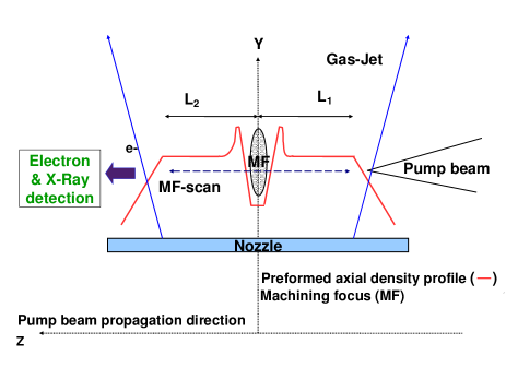
The experiments were performed at the Laboratoire d’Optique Appliquée with the TW, fs, Hz, m, Ti:Sapphire “Salle-Jaune” laser system[22]. The pump and machining beams, propagating orthogonal to each other, are focused onto a supersonic Helium gas-jet ejected from a mm diameter conic nozzle[23]. The density profile as characterised by Michelson interferometry has a plateau of length mm with m density gradients at the edges[18]. The pump beam with an energy of approximately J is focused by a cm focal length spherical mirror (f) and the machining beam with an energy of mJ is focused by a cylindrical lens system, with a tunable time-delay between the two beams. The FWHM spot size of the pump beam was estimated to be m m with a peak-intensity of approximately W/cm2(normalised vector potential ). The cylindrical focusing system for the machining beam consists of two cylindrical lenses (focal lengths of mm and mm), placed in series such that it generates a line focus of tunable length (FWHM - m) by varying the separation between the two lenses. The line focus of the machining beam is oriented in a direction orthogonal to the plane defined by the pump and machining beam axis, whereas the transverse width (FWHM spot- size m) of the line is aligned along the pump pulse propagation direction. The peak- intensity in the line focus estimated to be around W/cm2 ( ). The schematic experimental setup consisting of the machining and pump beam along with a probe beam (picked off from the pump beam) for Nomarski plasma interferometry[24] is shown in Fig. 1.
The machining laser pulse ionizes the gas-jet and creates a hot plasma localized in the line focal volume that hydrodynamically expands into the surrounding neutral gas. This leads to the formation of a density depleted channel with an inner lower density region surrounded by an expanding higher plasma density channel wall[25, 26]. Therefore the pump beam sees a longitudinal density- gradient at the edges of the channel as it propagates in a direction perpendicular to the machining beam. The density depletion at the focus of the machining beam creates the axial density gradient (for the pump beam) that induces injection of electrons into the wakefield generated by pump pulse. A schematic picture of the experimental target configuration with the preformed density-depletion region is shown in Fig. 2. The position of the density depleted channel and thereby the length () of the interaction distance following the injection position was tuned by the laterally scanning the machining focus (along the pump beam axis) with a motorised mirror (M) placed after cylindrical lens system and before the final focus. The aspect ratio of the line focus with an approximate length of m (FWHM) in the vertical direction (-axis) and a spot size of m (FWHM) along the pump pulse propagation direction ensures that the strongest density gradient as seen by the plasma wakefield of the pump pulse is predominantly longitudinal ( - axis).
In our experiments, the time delay between the pump and the machining laser pulse was fixed at ns following earlier experiments[18] where the timing had been optimized to obtain the strongest density gradients. Nomarski interferometry allowed us to measure precisely ( m) the axial location of the density depletion from the position of the distortion in the interferogram fringes (Fig. 3) arising due to the presence of the density channel in the path of the probe beam.
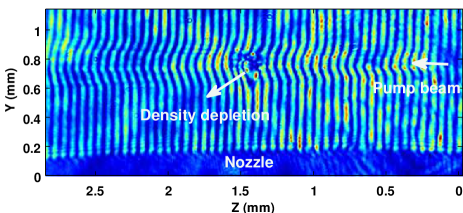
The axial width of the depletion zone estimated from the dimensions of the distorted region was approximately - m. However it was not possible to retrieve the longitudinal density profile in the distorted region from the interferometers due to the large phase shift caused by the machined plasma. The plasma wavelength in our experiments is estimated to be approximately - m corresponding to densities of cm-3. Since our conditions are similar to that in Ref. , the density-gradient scale length is likewise expected to be similar (m) and therefore the change in longitudinal density can be considered as gradual compared to plasma wavelength. As is evident from the integrity of the curved fringes throughout the gas-jet in the left side of the interferogram (Z mm), the density-depletion or injection zone in the path of the pump beam does not appear to disrupt its subsequent propagation and self-guiding. The pump pulse appears to be guided for lengths greater than m (Rayleigh range for a Gaussian focal spot size of m) both before and after the depletion zone. Controlled injection of electrons into the plasma wakefield occurs in the density- gradients of the density-depleted region and acceleration in the subsequent homogeneous plasma.
The energy of the accelerated electron bunch exiting the gas-jet was measured with a magnetic spectrometer consisting of Tesla, cm magnet and a Lanex phosphor screen imaged onto a -bit CCD camera. The spectrometer energy resolution was at MeV. The electron energy spectrum and absolute charge is obtained by post-processing the recorded data taking into account the calibration of the diagnostic[27].
III RESULTS & DISCUSSION
In our experiments, electrons are trapped and accelerated by the strong electric fields of the nonlinear plasma wave (plasma bubble)[28] excited by the intense and ultrashort pump laser pulse propagating in the gas-jet. Depending on specific plasma conditions, injection into the bubble can occur either by self-trapping or by controlled injection due to the preformed density-perturbation. The acceleration of electrons occurs in the matched plasma bubble regime of resonant laser wakefield acceleration [29, 30, 31](pulse length plasma wavelength/2) wherein the laser focal spot size is comparable to the bubble radius which is approximately of the order of half a plasma wavelength[32]. In order to differentiate between self-injection and density-gradient injection, electron spectrum was first recorded with only the pump beam focused onto the gas-jet. The density was reduced to minimize self-injection as much as possible without complete reduction of the detected charge. In these conditions (electron densities of about - cm-3), self- injection occurs occasionally, resulting in the production of a poor quality electron beam with a broadband electron energy distribution. The Lanex image and the corresponding electron spectrum for one such target shot are shown in Fig. 4. The spectrum of the self-injected electrons is consistently characterized by a large energy spread, low-energy dark current and considerable fluctuations in the spectral profile with high backround level on consecutive shots. The mean value of maximum electron energy (defined as cut-off edge in the logarithm of the spectral profile) was around MeV.
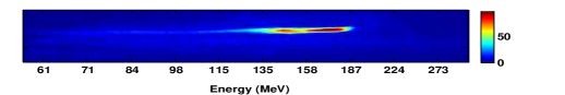
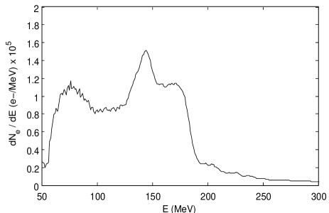
The electron signal in the high-energy tail ( MeV) of the spectrum (Fig. 4) is due to the high background level. For plasma densities much below the self-injection threshold, there were no distinct electron peaks with significant charge and the detected electron distribution was very close to the background level. The presence or absence of density-depleted region under these conditions did not have any significant effect on the electron spectrum because the densities are too low to excite a wakefield of sufficient amplitude that can trap and accelerate electrons. Self-injection at low densities would require laser system with greater power. At higher densities ( - cm-3), there is an increased probability of intermittent self - trapping of electrons with a poor accelerated beam quality. However for the same experimental conditions, firing the machining beam resulted in significant improvement of electron spectrum. The effect of the depletion region, in the form of localized electron injection at the density-gradients, dominates over any occasional self - injection. In contrast to the case of self - injection in a homogeneous plasma, the presence of the preformed density perturbation, leads to the acceleration of electrons with low energy spread, indicating the benefits of controlled injection for a fixed laser power.
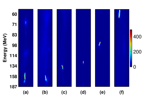
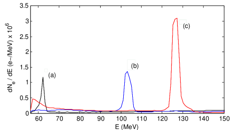
The axial location of the depletion region was varied by translating the position of the machining focus from the entrance to the exit of the gas-jet along the direction of the pump laser-axis. Electron spectrum data was recorded by scanning the location of the depletion region in steps of approximately mm and keeping all other experimental conditions unchanged. Electron beam images on the Lanex screen, obtained on selected shots for the scanned axial locations () of the machining focus in the range of mm to mm, are shown in Fig. 5. By changing the location of the density depletion and thereby the subsequent plasma interaction length, the final energy of the accelerated electrons is observed to be tunable. The spectra at different longitudinal locations () of the machining focus are shown in Fig. 6. The relative energy spread () of the quasi-monoenergetic peaks is around , limited by electron spectrometer in these few selected shots. Moreover the peak signal level in the density-gradient injected spectrum is approximately ten times higher than in the case of the self-injected electron spectrum. The improvement in electron beam quality with the machining beam highlights the advantages of controlled injection over uncontrolled self-injection, besides offering the flexibilty of tuning the electron energy with a single gas-jet in this particular experimental geometry.
Quasi-monoenergetic electrons were not detected when the depletion region was placed closer to the entrance in the first-half of the gas-jet, indicating that there is a threshold pump-pulse propagation distance after which the electrons begin to get injected in the longitudinal gradients of the depletion zone. The threshold length for our experimental conditions in the case of density-gradient injection was found to be approximately mm from the entrance of the gas-jet. Initially the focussed pump laser pulse has intensity () and parameters (spot size m, pulse length m) that are far from the matched, plasma bubble regime of resonant laser wakefield acceleration. For the matched regime at our plasma densities, the pump spot size has to be approximately equal to the bubble radius ( m). Therefore a long interaction distance is needed for the laser pulse to be sufficiently compressed transversally and longitudinally in order to drive a suitable nonlinear plasma wave for trapping electrons. Through an interplay of self-focusing, pulse-shortening and self- steepening, the spot size and the temporal duration of the pump laser pulse evolves to reach the matched regime after propagating for a certain axial distance from the focal position[29, 33, 34]. Quasi-static WAKE simulations[35] reveal that for a pump laser focus location in the range of [] m on the edge of the gas-jet, the initial normalized laser amplitude () of increases to a maximum value () of about after a propagation distance of approximately / mm, close to the experimentally observed threshold length. The increased laser amplitude is due to initial focal spot size and pulse duration compressing to approximately m and fs respectively. Though the exact values of the final laser parameters can change with the initial focus location, they are approximately close to the matched regime and favours the generation of a plasma bubble that can trap electrons as it traverses the density-depleted region. When the depletion region was placed closer to the exit of the gas-jet, quasi-monoenergetic electrons were observed with lower peak energy compared to the case when focused at the center. For propagation lengths () in the range of mm to mm, the spectrum had greater instability compared to case of lengths greater than mm presumably due to conditions being close to the matched regime or thresholds of electron injection. For the data set obtained with the machining beam, the probability of injection for which a quasi-monoenergetic electron distribution has been measured was approximately . In the other of case, no electrons were observed or when they were measured exhibited a broad energy distribution with a lower total charge. The shot to shot stability could be improved in the future by tuning the delay between the pump and the machining pulse (or the machining laser energy). The probability of injection could also be improved by better control over laser conditions that were perhaps sub-optimal during this particular experiment.
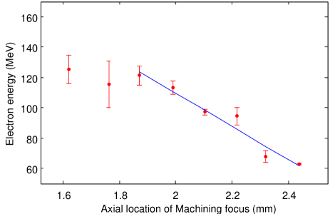
In Fig. 7, the final electron energy is plotted as a function of the density-depletion position . The data points are the mean of accumulated data from multiple shots and the straight line is a fit over the data corresponding to the in the range mm to mm. Since the axial location of machining focus () determines the plasma interaction length () following the depletion region (see Fig. 2), the maximum possible acceleration length () in a mm gas-jet approximately equals mm. Note that for our experimental conditions, the net acceleration length is less than the maximum possible value since the density-gradient injection is effective only for mm. The linear region in the graph (Fig. 7) quantifies the tunability of electron energy with acceleration length. The final electron energy on an average varied from MeV to MeV for an acceleration length varying from mm to mm equivalent to an acceleration gradient of GeV/m. This value is similar to that measured recently in colliding pulse injection[36] but lower than that expected from theory[32]. The scaling law predicts an acceleration gradient () of approximately GeV/m for our parameters, which is greater than the experimental measurement by a factor of . This could be probably due to a decrease of the laser intensity in the second half of the gas jet or the deformation of the bubble resulting from laser pulse evolution that reduces the electron energy gain. The acceleration length () in our case is limited to about mm. For machining focus locations () prior to mm, there appears to be a trends towards saturation of the mean electron energy. In this region, the spectrum is unstable with larger fluctuations in peak energy compared to the linear region. In some shots multiple peaked spectrum with energies as high as MeV in the highest energy peak, whereas in certain shots single peaks with much lower energies were observed. This could be due to evolution during laser propagation and the possibility of occurrence of multiple bunch injection on the density-gradient. The energy spectrum data was also analysed by plotting the maximum cut- off energy and a similar trend was observed with a slightly greater slope in the linear region.
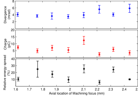
Finally the variation of various electron beam parameters such as relative energy spread, divergence and charge within the peaks of the spectrum were analysed as a function of the axial location of the machining focus (Fig. 8). The divergence, injected charge and relative energy spread is relatively constant across the acceleration length with approximate mean values ( std. error) of mrad, pC and respectively.
IV CONCLUSION
In summary, quasi-mononenergetic electrons were generated by using the longitudinal density gradients of a plasma density perturbation to induce controlled injection of electrons into the plasma wakefield. The density perturbation in the form of a density depleted plasma channel was created by a secondary machining beam. Final energy of the accelerated electrons was tuned from a maximum of MeV to MeV by varying the axial position of the density perturbation and thereby the injection location and the subsequent plasma interaction length. A threshold plasma length prior to depletion region was required for density-gradient injection to be effective whereas the final electron beam parameters such as energy-spread, divergence and charge were observed to be independent of the injection location. Controlled injection in a longitudinally inhomogeneous plasma appears better than self-injection in a homogeneous plasma in terms of final electron-beam quality for the same experimental conditions and offers the flexibility of tuning the electron energy with a single gas-jet. In future, accurate measurements of the density profile in the density-gradient injection scheme will allow for benchmarking numerical simulations to optimize the experimental parameters needed for generating high-quality electron beams.
ACKNOWLEDGMENTS
We thank J.P. Goddet and A. Tafzi for the operation of the laser system. We acknowledge the support of the European Research Council for funding the PARIS ERC project (Contract No. 226424), EC FP7 LASERLAB- EUROPE/LAPTECH (Contract No. 228334) and EU Access to Research Infrastructures Programme Project LASERLAB-EUROPE II.
References
- [1] T. Tajima and J.M. Dawson. Laser electron accelerator. Phy. Rev. Lett., 43(4):267–270, 1979.
- [2] V. Malka, J. Faure, Y.A. Gauduel, E. Lefebvre, A. Rousse, and K.T. Phuoc. Principles and applications of compact laser–plasma accelerators. Nature Physics, 4(6):447–453, 2008.
- [3] Y. Takada, N. Nakano, and H. Kuroda. Electron acceleration by laser driven plasma waves in inhomogeneous plasmas. App. Phys. Lett., 45(3):300–302, 1984.
- [4] S.V. Bulanov, V.I. Kirsanov, F. Pegoraro, and A.S. Sakharov. Charged particle and photon acceleration by wake field plasma waves in nonuniform plasmas. Laser Phys, 3(6):1078–1087, 1993.
- [5] S. Bulanov, N. Naumova, F. Pegoraro, and J. Sakai. Particle injection into the wave acceleration phase due to nonlinear wake wave breaking. Phys. Rev. E, 58(5):5257–5260, 1998.
- [6] S.V. Bulanov, F. Pegoraro, A.M. Pukhov, and A.S. Sakharov. Transverse-wake wave breaking. Phys. Rev. Lett., 78(22):4205–4208, 1997.
- [7] G. Fubiani, E. Esarey, C.B. Schroeder, and W.P. Leemans. Improvement of electron beam quality in optical injection schemes using negative plasma density gradients. Phys. Rev. E, 73(2):026402, 2006.
- [8] D. Umstadter, J. K. Kim, and E. Dodd. Laser injection of ultrashort electron pulses into wakefield plasma waves. Phys. Rev. Lett., 76:2073–2076, 1996.
- [9] J. Faure, C. Rechatin, A. Norlin, A. Lifschitz, Y. Glinec, and V. Malka. Controlled injection and acceleration of electrons in plasma wakefields by colliding laser pulses. Nature, 444(7120):737–739, 2006.
- [10] J. Vieira, S.F. Martins, V.B. Pathak, R.A. Fonseca, W.B. Mori, and L.O. Silva. Magnetic control of particle injection in plasma based accelerators. Phys. Rev. Lett., 106:225001, 2011.
- [11] R. G. Hemker, N. M. Hafz, and M. Uesaka. Computer simulations of a single-laser double-gas-jet wakefield accelerator concept. Phys. Rev. ST Accel. Beams, 5(4):041301, 2002.
- [12] C.G.R. Geddes, K. Nakamura, G.R. Plateau, C. Toth, E. Cormier-Michel, E. Esarey, C.B. Schroeder, J.R. Cary, and W.P. Leemans. Plasma-density-gradient injection of low absolute-momentum-spread electron bunches. Phys. Rev. Lett., 100(21):215004, 2008.
- [13] A.J. Gonsalves, K. Nakamura, C. Lin, D. Panasenko, S. Shiraishi, T. Sokollik, C. Benedetti, C.B. Schroeder, C.G.R Geddes, J. van Tilborg, et al. Tunable laser plasma accelerator based on longitudinal density tailoring. Nature Physics, 2011.
- [14] H. Suk, N. Barov, J.B. Rosenzweig, and E. Esarey. Plasma electron trapping and acceleration in a plasma wake field using a density transition. Phys. Rev. Lett., 86(6):1011–1014, 2001.
- [15] H. Suk, H.J. Lee, and I.S. Ko. Generation of high-energy electrons by a femtosecond terawatt laser propagating through a sharp downward density transition. JOSA B, 21(7):1391–1396, 2004.
- [16] K. Koyama, A. Yamazaki, A. Maekawa, M. Uesaka, T. Hosokai, M. Miyashita, S. Masuda, and E. Miura. Laser-plasma electron accelerator for all-optical inverse Compton X-ray source. Nuclear Instruments and Methods in Physics Research Section A, 608(1):S51–S53, 2009.
- [17] K. Schmid, A. Buck, C.M.S. Sears, J.M Mikhailova, R. Tautz, D. Herrmann, M. Geissler, F. Krausz, and L. Veisz. Density-transition based electron injector for laser driven wakefield accelerators. Phys. Rev. ST Accel. Beams, 13(9):091301, 2010.
- [18] J. Faure, C. Rechatin, O. Lundh, L. Ammoura, and V. Malka. Injection and acceleration of quasimonoenergetic relativistic electron beams using density gradients at the edges of a plasma channel. Physics of Plasmas, 17:083107, 2010.
- [19] N. Hafz, H.J. Lee, J.U. Kim, G.H. Kim, H. Suk, and J. Lee. Femtosecond X-ray generation via the Thomson scattering of a Terawatt laser from electron bunches produced from the LWFA utilizing a plasma density transition. IEEE Transactions on Plasma Science, 31(6):1388–1394, 2003.
- [20] J.U. Kim, N. Hafz, and H. Suk. Electron trapping and acceleration across a parabolic plasma density profile. Phys. Rev. E, 69(2):026409, 2004.
- [21] C.-T. Hsieh, C.-M. Huang, C.-L. Chang, Y.-C. Ho, Y.-S. Chen, J.-Y. Lin, J. Wang, and S.-Y. Chen. Tomography of injection and acceleration of monoenergetic electrons in a laser-wakefield accelerator. Phys. Rev. Lett., 96:095001, 2006.
- [22] M. Pittman, S. Ferré, J.P. Rousseau, L. Notebaert, J.P. Chambaret, and G. Chériaux. Design and characterization of a near-diffraction-limited femtosecond 100-TW 10-Hz high-intensity laser system. App. Phys. B: Lasers and Optics, 74(6):529–535, 2002.
- [23] S. Semushin and V. Malka. High density gas jet nozzle design for laser target production. Rev. Sci. Instru., 72:2961, 2001.
- [24] R. Benattar, C. Popovics, and R. Sigel. Polarized light interferometer for laser fusion studies. Rev. Sci. Instru., 50(12):1583–1586, 1979.
- [25] C. G. Durfee and H. M. Milchberg. Light pipe for high intensity laser pulses. Phys. Rev. Lett., 71:2409–2412, 1993.
- [26] P. Volfbeyn, E. Esarey, and W. P. Leemans. Guiding of laser pulses in plasma channels created by the ignitor-heater technique. Physics of Plasmas, 6(5):2269–2277, 1999.
- [27] Y. Glinec, J. Faure, A. Guemnie-Tafo, V. Malka, H. Monard, J.P. Larbre, V. De Waele, J.L. Marignier, and M. Mostafavi. Absolute calibration for a broad range single shot electron spectrometer. Rev. Sci. Instru., 77:103301, 2006.
- [28] A. Pukhov and J. Meyer-ter Vehn. Laser wake field acceleration: the highly non-linear broken-wave regime. App. Phys. B: Lasers and Optics, 74:355–361, 2002.
- [29] V. Malka, S. Fritzler, E. Lefebvre, M. M. Aleonard, F. Burgy, J. P. Chambaret, J. F. Chemin, K. Krushelnick, G. Malka, S. P. D. Mangles, Z. Najmudin, M. Pittman, J. P. Rousseau, J. N. Scheurer, B. Walton, and A. E. Dangor. Electron acceleration by a wake field forced by an intense ultrashort laser pulse. Science, 298(5598):1596–1600, 2002.
- [30] S.P.D. Mangles, C.D. Murphy, Z. Najmudin, A.G.R. Thomas, J.L. Collier, A.E. Dangor, E.J. Divall, P.S. Foster, J.G. Gallacher, C.J. Hooker, et al. Monoenergetic beams of relativistic electrons from intense laser–plasma interactions. Nature, 431(7008):535–538, 2004.
- [31] J. Faure, Y. Glinec, A. Pukhov, S. Kiselev, S. Gordienko, E. Lefebvre, J.P. Rousseau, F. Burgy, and V. Malka. A laser–plasma accelerator producing monoenergetic electron beams. Nature, 431(7008):541–544, 2004.
- [32] W. Lu, M. Tzoufras, C. Joshi, F. S. Tsung, W. B. Mori, J. Vieira, R. A. Fonseca, and L. O. Silva. Generating multi-gev electron bunches using single stage laser wakefield acceleration in a 3D nonlinear regime. Phys. Rev. ST Accel. Beams, 10:061301, 2007.
- [33] J. Faure, Y. Glinec, J. J. Santos, F. Ewald, J.-P. Rousseau, S. Kiselev, A. Pukhov, T. Hosokai, and V. Malka. Observation of laser-pulse shortening in nonlinear plasma waves. Phys. Rev. Lett., 95:205003, 2005.
- [34] A. G. R. Thomas, Z. Najmudin, S. P. D. Mangles, C. D. Murphy, A. E. Dangor, C. Kamperidis, K. L. Lancaster, W. B. Mori, P. A. Norreys, W. Rozmus, and K. Krushelnick. Effect of laser-focusing conditions on propagation and monoenergetic electron production in laser-wakefield accelerators. Phys Rev. Lett., 98:095004, 2007.
- [35] P. Mora and Jr. T. M. Antonsen. Kinetic modeling of intense, short laser pulses propagating in tenuous plasmas. Physics of Plasmas, 4(1):217–229, 1997.
- [36] S. Corde, K. Ta Phuoc, R. Fitour, J. Faure, A. Tafzi, J. P. Goddet, V. Malka, and A. Rousse. Controlled betatron x-ray radiation from tunable optically injected electrons. Phys. Rev. Lett., 107:255003, 2011.