Relay-Assisted Interference Network: Degrees of Freedom
Abstract
This paper investigates the degrees of freedom of the interference channel in the presence of a dedicated MIMO relay. The relay is used to manage the interference at the receivers. It is assumed that all nodes including the relay have channel state information only for their own links and that the relay has antennas in a -user network. We pose the question: What is the benefit of exploiting the direct links from the source to destinations compared to a simpler two-hop strategy. To answer this question, we first establish the degrees of freedom of the interference channel with a MIMO relay, showing that a -pair network with a MIMO relay has degrees of freedom. Thus, appropriate signaling in a two-hop scenario captures the degrees of freedom without the need for the direct links. We then consider more sophisticated encoding strategies in search of other ways to exploit the direct links. Using a number of hybrid encoding strategies, we obtain non-asymptotic achievable sum-rates. We investigate the case where the relay (unlike other nodes) has access to abundant power, showing that when sources have power and the relay is allowed power proportional to , the full degrees of freedom are available to the network.
Index Terms:
Degrees of freedom, interference channel, relay channel, wireless networks.I Introduction
In addition to historical significance in network information theory, a better understanding of the interference channel [1] is becoming increasingly practically important, since many current wireless communication systems are interference-limited. Examples include ad-hoc networks with peer-to-peer communications that lack infrastructure and hence transmission coordination, interference between adjacent networks in wireless LAN systems, as well as cognitive networks, where primary and secondary users transmit in the same band.
The capacity of the interference channel in the most general case remains unknown, thus a number of partial approaches for investigating the interference channel have been pursued. One of the tools for understanding the behavior of multi-terminal networks is the degrees of freedom (DOF), also known as the multiplexing gain or the pre-log factor, which characterizes the scaling behavior of a network throughput at high signal-to-noise ratios (SNR). We formally define the degrees of freedom as follows [2]:
| (1) |
where is the power constraint at each source node, is the noise variance at a destination and is the network sum-rate capacity. For example, the maximum degrees of freedom of a two-user (single-antenna) Gaussian interference channel is equal to one [3].
This work investigates the effect of having a dedicated MIMO relay shared by several source-destination pairs on the degrees of freedom of such network. The main issue is whether with simple single-user decoding at the destinations, exploiting direct links is of a benefit.
Recent advances in network information theory have led to the characterization of the degrees of freedom of several networks. It is well known that the MIMO MAC and MIMO BC have full degrees of freedom [4, 5]. Thus, the degrees of freedom in the MIMO MAC and BC channels do not increase with transmit and receive cooperation, respectively.
Recently, the phenomenon of interference alignment has led to new results that characterize the degrees of freedom in various interference networks. The idea of interference alignment is for the transmissions to coordinate in such a manner such that at the receivers the interference signals overlap in certain dimensions and therefore other dimensions are left interference-free. Via interference alignment, in a -user time-varying interference network degrees of freedom are achieved almost surely [6].
The first attempt to study the effect of relaying on the degrees of freedom of the interference network was performed in [3] and [7]. A rather negative result was obtained, showing that cooperation over fading links between the sources, between the destinations, or both, cannot improve the degrees of freedom of an interference network. On the other hand, if perfect cooperation between sources (destinations) is assumed, the network can mimic a MIMO system with antennas co-located at the transmitting (receiving) side as mentioned previously. In [8], the links between sources or between destination are considered having phase fading and it is shown that cooperation can help in increasing the throughput of a two-user interference channel close to rates achieved by a MIMO system. Considering distributed dedicated relays, Morgenshtern and Bölcskei [9] showed that the interference network can decouple. This is based on devising an amplify-and-forward two-hop strategy that utilize full (but local) CSI at the relays and subject to having the number of relays greater that , where is the number of source-destination pairs. A similar decoupling can be achieved by fewer relays, specifically with the cost of having global CSI at the relays [10]. The DMT performance of this scheme was further analyzed in [11]. Finally, a two-hop network with MIMO relaying decouples into a MIMO-MAC followed by a MIMO-BC each achieving full degrees of freedom [12], therefore the DoF is achievable with a two-hop transmission.
The addition of a MIMO relay to an interference channel (including direct links) gives rise to a network model that we denote the interference MIMO relay channel (IMRC). In this paper we first establish the degrees of freedom of the Gaussian IMRC with the source and destination nodes having one antenna each. Achievability is demonstrated with a two-hop scheme, without exploiting the direct links from the sources to the destinations. The upper bound on the degrees of freedom is obtained by specializing the recently developed upper bounds in [13]. We establish that the interference MIMO relay channel has degrees of freedom.
We then take the investigation one step further to consider degrees of freedom beyond . We devise new combinations of coding strategies that are inspired by the coding schemes used in relay channels, as well as MIMO MAC and MIMO broadcast channels. These coding strategies attempt to exploit the direct links but at the same time manage the interference at the receivers using the MIMO relay. It is assumed that all nodes, including the relay, have only their own channel state information. We further consider the effect of the availability of abundant power at the relay. This is motivated by real-world scenarios where a single relay tower, with easy access to power, is assisting many mobiles. We wish to understand whether the devised coding scheme and the additional power at the relay can improve the DOF of the channel. Also, we investigate the minimum amount of power needed to impart maximum degrees of freedom to the network. We find that if the relay has antennas and power proportional to , it can impart the maximum degrees of freedom to a -user network whose users have power , regardless of the number of users (c.f. of our definition of DOF in (1)).
The remainder of this paper is organized as follows. Section II explains the notations used in the paper and provides the system model. Section III establishes the DOF of the -user IMRC. Section IV states the main result of the paper and presents the detailed coding strategies that exploits the direct links and abundant power at the relay. We corroborate our analytical findings by numerical results in Section V. Finally, Section VI concludes the paper.
II System Model
Throughout the paper, lower-case and upper-case boldface letters denote vectors and matrices, respectively. The determinant of matrix , it’s transpose and Hermitian are denoted , and , respectively. The norm of a vector is denoted by . stands for the base-2 logarithm. All rates are expressed in bits/channel use.
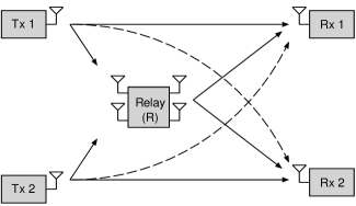
The interference MIMO relay channel (IMRC) is depicted in Fig. 1. Nodes and attempt to communicate independent messages and to their respective receivers, possibly with help from the relay (node ). The relay is assumed to be equipped with antennas, where while all other nodes have one antenna each. All links are subject to flat fading which remains constant during the transmission period. The channels from the sources to their corresponding destinations, from the sources to the relay and from the relay to destinations are denoted by the letters, , and , respectively. A subscript is used to index the transmitting and receiving nodes, and , respectively.
The input-output relation of a Gaussian IMRC is given by:
| (2) | ||||
| (3) | ||||
| (4) |
where , and are the channel outputs at receivers , and the relay, , and are the transmitted signals. The variables , and denote zero-mean, unit-variance additive white Gaussian noises at the receivers. We assume individual block power constraints on the transmitting nodes. Nodes and have equal transmit power constraint of , i.e.
| (5) |
where is the symbol index within a block of symbols.
We assume that the relay node has block power constraint , which may be different from and will be specified in each instance in the sequel. The relay uses a decode-and-forward scheme [14] that includes linear pre-coding, in a manner to be explained shortly. The channel state information (CSI) knowledge assumptions are as follows. Transmitters and each have perfect knowledge about their own transmit-side CSI while receivers and have perfect knowledge of their receive-side CSI. The relay is assumed to have knowledge of its incoming and outgoing links. The relay is assumed to operate in full-duplex mode, i.e., it can receive and transmit at the same time. Throughout this paper, we assume the input alphabets to be Gaussian. The average probability of error is defined as follows:
| (6) |
where, denotes an estimate of . The rate of transmission from node is , where is the size of the message transmitted by node . A rate pair is said to be achievable for the interference MIMO relay channel if there exist a sequence of codes with average probability of error as . A -user interference network with a single MIMO relay can be defined as a straightforward extension to the above model.
III The Degrees of Freedom of IMRC
The first main result of this paper is as follows:
Theorem 1
The degrees of freedom of the interference MIMO relay network is .
Proof: Achievability is established with a simple two-hop scheme. The first phase where the sources transmit the signals and the MIMO relay decodes is a MIMO MAC channel. It is well known that this channel achieves the full degrees-of-freedom. The second phase where the relay transmit to the receivers is a MIMO BC and again is know to achieve DOF. The transmission in two hops entails a penalty of one half in the DOF. Thus, DOF are achieved for the IMRC.
Now, the converse. A recent work [13] produced an elegant approach to find upper bounds on fully connected interference and X networks with relays and feedback. The upper bound on a fully connected network can be specialized to the network we study in this paper where , and refer to the number of sources, relays and distentions in the network. A fully connected network means that there is a message from every source to every destination. For completeness, we will first state the main result on the upper bound on the degrees of freedom of the network.
Theorem 2
[13] If represents the degrees of freedom region of the node network, then the total degrees of freedoms can be upper bounded as follows:
Note that [13] derives upper bound not only on the degrees of freedom of the but on the whole degrees of freedom region. The interested reader is refered to [13] for further details.
Now for the -user interference network, using the following corollary from [13] the exact degrees of freedom is obtained.
Corollary 1
Consider a fully connected user interference network with relays, where all the channel coefficients are time-varying/frequency-selective with values drawn randomly from a continuous distribution with support bounded below by a non-zero constant. Let all nodes be full-duplex allowing noisy transmitter/receiver cooperation. Also, let the source and relay nodes receive perfect feedback from all nodes. Then the interference network has degrees of freedom.
The bounds in the previous theorem and corollary are applicable to the MIMO relay in the IMRC, because the proof of the converse assumes full cooperation between the distributed relay nodes (see observation in [13]). Also, feedback and time/frequency selectivity of the channel do not reduce the degrees of freedom of the channel. Therefore, due to the matching achievability and converse results, the DOF of IMRC is established to be .
IV Degrees of Freedom Beyond
In the previous section, the DOF of the interference channel with a MIMO relay was shown to be , which is also achievable via a two-hop strategy. Therefore, the direct links do not contribute to the DOF of the channel. However, we will show that the DOF can be larger than by exploiting the direct links in addition to a more powerful MIMO relay.
We start by developing a coding strategy that uses the direct links and investigate, through the derived sum rate of the channel, the reason for the inefficiency of the direct links in improving the DOF. Then, the effect of abundant power at the relay on the DOF is studied.
IV-A Coding Strategies and Achievable Rates
The idea of the upcoming coding strategies is to use the relay in a way that minimizes the interference at the receivers. This task is highly nontrivial because the causality of the relay prohibits straight-forward interference cancelation. Therefore, sophisticated coding and power control strategies are needed to possibly manage the interference at the receivers.
Consider a transmission period of blocks, each of symbols. It is assumed that is sufficiently large to allow reliable decoding. Without loss of generality, at first a two-user network is considered. Nodes and send sequences of messages and , respectively, over the channel in transmissions, where denotes the block index, . The rate pair approaches as .
IV-B Encoding at the Sources
The source uses the super-position block Markov encoding technique devised in [14]. In particular at any block ,
| (7) | ||||
| (8) |
where and are i.i.d Gaussian codebooks encoding the messages of the current and the previous blocks with powers and , respectively, according to the power constraint
| (9) |
Similar definitions hold for the signal components transmitted by node , and .
IV-C Decoding and Re-encoding at the Relay
A space division multiple-access (SDMA) approach is used to communicate between nodes , and the MIMO relay. Therefore, both sources transmit simultaneously and the MIMO relay attempts decoding both signals. At the end block , given that the relay decoded both messages and correctly, it can decode the messages and of both users while achieving a . This can be achieved by a zero-forcing strategy, as long as the relay has no fewer antennas as the number of transmit nodes, and is made possible by the independence of the users’ channels to the relay that is a result of spatial separation. The sum-rate constraint for correct decoding at the relay is given by [15, Section 10.1]:
| (10) |
where , , and is the identity matrix.
Now, to the relay encoding strategies. Ideally, it would be desirable for the relay to cancel the entire interference at each receiver. However, due to causality, the relay can only cancel the interference arising from signals that it has already decoded. Thus, even if everything is accomplished perfectly, not all of the interferences will be canceled. The question is, if interferences cannot be fully removed, then how must the remaining interference be managed so that a good result may be obtained in terms of the degrees of freedom. This issue will be addressed in the sequel via power allocation policies at the sources and at the relay.
The channel from the relay to both destinations is similar to a Gaussian MIMO broadcast channel whose capacity region has been recently determined [16]. To help in canceling the interference, the relay uses a modified zero-forcing beamforming (ZF-BF) strategy [17]. ZF-BF achieves the maximum degrees of freedom of the sum-rate capacity of a Gaussian MIMO BC, although it is in general suboptimal compared to the capacity-achieving dirty-paper coding (DPC) strategy. The relay constructs and transmits the following signal:
| (11) |
where and are complex beamforming vectors. For simplicity, we assume the relay divides its power equally between the two signals components, i.e. . Proper selection of beamforming vectors (magnitudes and phases) allows partial suppression of interference at the receivers as will be described later.
IV-D Decoding at the Destinations
Given the structure of the signal formed by the relay, we re-write (2) and (3) as follows:
| (12) | ||||
| (13) |
Therefore, the beamforming vectors at the relay and are selected such that and . The derivation of and is discussed in the Appendix. This will cancel part of the interference seen by each receiver, thus the received signals are modified to:
| (14) | ||||
| (15) |
Receivers and can use Willems’s backward decoding to decode their intended signals [18]. Backward decoding imposes decoding delays, however, it simplifies the analysis compared to list decoding or window decoding [19]. Backward decoding starts from block . The receivers have interference-free channels to decode and . In block , they pre-subtract the components of and before attempting to decode and . Therefore, at any block the received signals can be further reduced to:
| (16) | ||||
| (17) |
It is clear that channel does not have the typical form of an interference channel,
| (18) |
where and . Hence, we cannot further reduce the channel to a known form. Each receiver will attempt single user decoding, i.e. treating interference as noise, and thus can decode their respective messages and reliably if:
| (19) | ||||
| (20) |
where equals when the CSI of the direct links, and , is not available at the relay. The non-coherent addition of the signals coming from the sources and the relay which entails a penalty in the achievable rate but does not affect the DOF. We can set for perfect in-phase addition of the signals coming from the sources and the relay.111The interested reader can refer to [20] for details on the capacity analysis of the full-duplex (a)synchronous relay channel with fixed and variable channel gains.
We proceed to specify power allocation strategies, ranging from very simple to more sophisticated, and explore the corresponding achievable degrees of freedom. Let and . According to this power allocation, the multi-access part of the channel according to (10) achieves . However, according to (IV-D) and (20), the signal and interference have the same power order and hence a is achieved. Therefore, the degrees of freedom of the network in this case is zero. Clearly this is not a desirable solution.
Now consider an asymmetric power allocation policy characterized by , and . In other words, the cooperative information –also known as the resolution information– has a higher power than the information of the current block of transmission. It is clear that is achieved on the multi-access side of the channel. On the other hand, each of (IV-D) and (20) provides a pre-log factor of leading to a sum-rate for the direct link with relaying. Therefore, an overall is achieved.
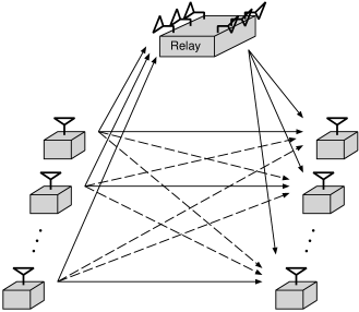
The impact of the above results are clearer when considered in the context of users. The previous coding strategies can easily be extended to an interference network where users transmit simultaneously and a MIMO relay having antennas helps all nodes in their transmission (see Figure 2).
Having a MIMO relay in a network with source-destination pairs can have a large impact on the DOF either through a two-hop strategy or through the coding strategy developed in this section. Specifically DOF are easily achieved compared to DOF of with simple time-sharing strategy in the absence of the relay.
So far, by exploiting the direct links, the DOF are no better than the simple two-hop strategy. Next, we explore a way to actually capture the whole DOF of the channel.
IV-E Abundant Power at the Relay
Assume at all source nodes while at the relay we have (or in general ). In this case, the network will achieve degrees of freedom of , thanks to the pre-coding strategy employed by the relay, which allows the relay to avoid causing interference at any node.
Theorem 3
The K-users Interference MIMO Relay Channel (IMRC) achieves (full) degrees of freedom (per the definition given in (1)), with the source nodes having each a per block power constraint of and the MIMO relay having a power constraint of and antennas.
Note that our definition of the degrees of freedom in (1) concentrates on the power of information-bearing nodes, thus allowing us to study the effect of abundant power at the relay for this special case.
Although the degrees of freedom are achieved with a relay that enjoys power proportional to , it is noteworthy that the required relay power is independent on .
V Numerical Results
We corroborate the analysis by the following numerical example of an interference MIMO relay channel. The following setup is considered:
-
•
Two-user channel and the relay has two antennas, i.e., .
-
•
The noise variance at all nodes =1.
-
•
The magnitude of channel coefficients are selected as: , , , , , , and .
An interference channel, without the MIMO relay, can be transformed into a well known form in the literature known as the standard form (see e.g. [21]). The original interference channel has the following standard form channel gains, under the assumption of unity noise variance at all nodes,
| (21) |
The above values of the channel coefficients results in . Thus, without the MIMO relay, the interference is considered weak/moderate. This is the case where the capacity region of the interference channel is unknown and where a form of relaying will be of greater impact on the capacity [7].
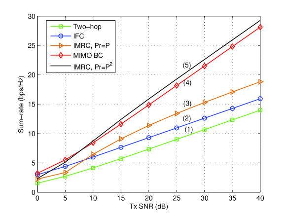
Figure 3 depicts the sum-rate of five schemes. Curve is the sum-rate with a simple two-hop scheme. Curve depicts the best known achievable sum-rate for the interference channel (IFC), with no relay present, using the Han-Kobayashi coding scheme. This scheme involves rate splitting, joint decoding at the receivers and moreover it includes a time-sharing random variable that switches between time-division transmission and simultaneous transmission by the source nodes. The cardinality of the time-sharing parameter is set to two and furthermore the power allocation of the rate-splitting scheme is optimized. This corresponds to curve of [22]. Curve is the computable sum-rate of the interference MIMO relay channel (IMRC) with the coding strategy discussed in Section IV and under the asymmetric power allocation policy characterized by , and . Curve is the case where no relay is present and the two sources have ideal cooperation leading to a MIMO BC model. The optimal power allocation and hence the sum-rate capacity are computed according to Algorithm 2 of [23]. Finally, Curve is the sum rate of the IMRC, however, under the assumption of abundant power at the relay, specifically, at the source nodes while at the relay we have .
We emphasize here that for IMRC, we use independent decoding at the nodes and we do not fully optimize the power allocation strategies at the sources and the relay. The focus of this paper is on the DOF and thus the throughput optimization and analysis at finite SNR is outside the scope of this paper.
The following conclusions can be drawn from the figure:
-
•
The three lower curves share the same slope as the corresponding schemes have a . The upper two curves also share another slope verifying that the IMRC with achieves the full DOF of the channel.
-
•
It is interesting to see that the fully optimized IFC as explained above can achieve higher throughput than the simple two-hop scheme; the fully optimized IFC in this figure has a total power equal to the total power of all the nodes in the IMRC, including the relay. The simple two-hop scheme does not involve optimal power allocation at the source nor joint decoding at the destinations.
-
•
While the coding strategy devised in this paper to exploit the direct links of the IMRC of Curve shares the same DOF of IFC, but as it can be seen in the figure, this strategy leads to noticeable gains in the sum-rate for medium and high SNR values over the IFC.
-
•
The IMRC scheme with abundant power at the relay, Curve , presents a substitute strategy for the cooperative MIMO, Curve . Cooperative MIMO is a scheme of interest in the wireless industry to improve the throughput for the uplink of cellular networks.
VI Discussion
In this work, we characterize the high-SNR sum-rate behavior of an interference channel with a MIMO relay. First, we establish that the degrees of freedom of the interference MIMO relay channel to be only . Therefore, in this case exploiting the direct links does not provide significant throughput enhancement at high SNR. Then, we consider a more sophisticated coding scheme that exploits the direct links and the possibility of abundant power at the relay. We show that if the transmit/receive nodes have power proportional to , and the relay has power proportional to , all degrees of freedom of the channel become available. This result is achieved under modest channel knowledge assumption at the network nodes and with the assumption of single user decoding at the destinations.
While we consider the case of full-duplex relay, one can devise similar signaling strategies for the half-duplex case. However, the block-Markov coding is not required. A brief description of a possible coding scheme is given as follows. The sources transmit all the time. However, they divide each block of their transmission into two halves. Each source node transmits the same message in the two halves using i.i.d. Gaussian code books. During the second half, the relay transmits and manages the interference as discussed above in the full-duplex case. At the destinations, the received signals at the first and second halves form two Gaussian parallel channels, the first sees interference while the other is interference-free. It can be easily shown that the maximum degrees-of-freedom of this scheme is . As we know from Theorem 1, a two-hop strategy suffices to achieve a degrees-of-freedom. However, exploiting the direct links provides an increase in the throughput compared to two-hop communications for all signal-to-noise-ratios.
Several directions naturally arise for future work. Our analysis concentrates on the high SNR behavior of the network throughput, thus many parameters of the IMRC can be further optimized for non-asymptotic SNR values. More complex coding/decoding techniques can also be employed, for example, a modified Han-Kobayashi scheme (in the presence of the MIMO relay) that combines rate-splitting, time-sharing (TDM), relaying and joint decoding at the receivers.
Finally, it is worth mentioning that since the time of submission of this paper for publication there has been a surge of research activity in the area of interference networks. In particular, the time/frequencey non-selective interference channel has been studied lately in more depth and a better understanding of its performance limits has been developed. The interested reader can refer to [24, 25] and the references therein.
For simplicity we consider the two user case. Denote by and the beamforming vectors at the relay.
The following conditions govern the selection of the beamforming vector ,
-
1.
-
2.
-
3.
where is the phase of the (direct) channel between source node and the intended destination node. Similarly, One can write the conditions for selecting .
The first condition is related to power scaling at the relay. The second condition is the one responsible to reduce the interference seen by the destination nodes. The third condition is optional, it is responsible for coherent combination of the desired signal component at the intended destination. It requires though global channel knowledge at the relay.
A closed form solution for the three simultaneous conditions is not feasible. Instead we assume the lack of the third condition which does not affect the DOF achieved by the coding scheme for IMRC explained in this paper and simplifies the channel knowledge requirements.
Solving for and , one gets for , and ,
| (22) |
and,
| (23) |
References
- [1] A. B. Carleial, “Interference channels,” IEEE Trans. Inform. Theory, vol. 24, no. 1, pp. 60–70, Jan. 1978.
- [2] K. Azarian, H. El Gamal, and P. Schniter, “On the achievable diversity-multiplexing tradeoff in half-duplex cooperative channels,” IEEE Trans. Inform. Theory, vol. 51, no. 12, pp. 4152–4172, Dec 2005.
- [3] A. Høst-Madsen, “Capacity bounds for cooperative diversity,” IEEE Trans. Inform. Theory, vol. 52, no. 4, pp. 1522–1544, Apr. 2006.
- [4] D. Tse, P. Viswanath, and L. Zheng, “Diversity-multiplexing tradeoff in multiple-access channels,” IEEE Trans. Inform. Theory, vol. 50, no. 9, pp. 1859–1874, Sept. 2004.
- [5] S. Vishwanath, N. Jindal, and A. Goldsmith, “Duality, achievable rates, and sum-rate capacity of MIMO broadcast channels,” IEEE Trans. Inform. Theory, vol. 49, no. 10, pp. 2895–2909, Oct. 2003.
- [6] V. R. Cadambe and S. A. Jafar, “Interference alignment and degrees of freedom of the K-user interference channel,” IEEE Trans. Inform. Theory, vol. 54, no. 8, pp. 3425–3441, August 2008.
- [7] A. Høst-Madsen and A. Nosratinia, “The multiplexing gain of wireless networks,” in Proc. IEEE International Symposium on Information Theory (ISIT), Adelaide, Australia, Sep. 2005, pp. 2310–2314.
- [8] C. T. K. Ng, N. Jindal, A. J. Goldsmith, and U. Mitra, “Capacity gain from two-transmitter and two-receiver cooperation,” IEEE Trans. Inform. Theory, vol. 53, no. 10, pp. 3822 – 3827, Oct 2007.
- [9] V. I. Morgenshtern and H. Bölcskei, “Crystallization in large wireless networks,” IEEE Trans. Inform. Theory, vol. 53, no. 10, pp. 3319 – 3349, Oct 2007.
- [10] A. F. Dana and B. Hassibi, “On the power efficiency of sensory and ad hoc wireless networks,” IEEE Trans. Inform. Theory, vol. 52, no. 7, pp. 2890 – 2914, July 2006.
- [11] C. K. Rao, “Asymptotic analysis of wireless systems with Rayleigh fading,” Ph.D. dissertation, Caltech, Pasadena, CA., U.S.A., 2007.
- [12] S. A. Jafar and S. Shamai, “Degrees of freedom region for the MIMO X channel,” IEEE Trans. Inform. Theory, vol. 54, no. 1, pp. 151–170, Jan. 2008.
- [13] V. R. Cadambe and S. A. Jafar, “Degrees of freedom of wireless networks with relays, feedback, co-operation and full duplex operation,” IEEE Trans. Inform. Theory, vol. 55, no. 5, pp. 2334–2344, May 2009.
- [14] T. Cover and A. E. Gamal, “Capacity theorems for the relay channel,” IEEE Trans. Inform. Theory, vol. 25, no. 5, pp. 572–584, 1979.
- [15] D. Tse and P. Viswanath, Fundamentals of Wireless Communication. New York, NY, USA: Cambridge University Press, 2005.
- [16] H. Weingarten, Y. Steinberg, and S. Shamai, “The capacity region of the Gaussian multiple-input multiple-output broadcast channel,” IEEE Trans. Inform. Theory, vol. 52, no. 9, pp. 3936–3964, Sep. 2006.
- [17] T. Yoo and A. Goldsmith, “On the optimality of multiantenna broadcast scheduling using zero-forcing beamforming,” IEEE J. Select. Areas Commun., vol. 24, no. 3, pp. 528–541, Mar. 2006.
- [18] F. M. J. Willems, “Information-theoretical results for the discrete memoryless multiple access channel,” Ph.D. dissertation, Katholieke Univ. Leuven, Leuven, Belgium, October 1982.
- [19] G. Kramer, M. Gastpar, and P. Gupta, “Cooperative strategies and capacity theorems for relay networks,” IEEE Trans. Inform. Theory, vol. 51, no. 9, pp. 3037–3063, 2005.
- [20] A. Høst-Madsen and J. Zhang, “Capacity bounds and power allocation for wireless relay channels,” IEEE Trans. Inform. Theory, vol. 51, no. 6, pp. 2020–2040, June 2005.
- [21] G. Kramer, “Review of rate regions for interference channels,” in International Zurich Seminar on Communications, Feb. 2006, pp. 162–165.
- [22] I. Sason, “On achievable rate regions for the Gaussian interfernce channel,” IEEE Trans. Inform. Theory, vol. 50, no. 6, pp. 1345–1356, June 2004.
- [23] N. Jindal, W. Rhee, S. Vishwanath, S. A. Jafar, and A. Goldsmith, “Sum power iterative water-filling for multi-antenna Gaussian broadcast channels,” IEEE Trans. Inform. Theory, vol. 51, no. 4, pp. 1570–1580, Apr. 2005.
- [24] R. Etkin and E. Ordentlich, “On the degrees-of-freedom of the K-user Gaussian interference channel,” in Proc. IEEE International Symposium on Information Theory (ISIT), Seoul, S. Korea, June-July 2009, pp. 1919–1923.
- [25] A. S. Motahari, S. O. Gharan, M.-A. Maddah-Ali, and A. K. Khandani, “Real interference alignment: Exploiting the potential of single antenna systems,” IEEE Trans. Inform. Theory, 2009, submitted for publication.