Scheme for generating and transporting THz radiation to the X-ray experimental hall at the European XFEL
Abstract
The design of a THz edge radiation source for the European XFEL is presented. We consider generation of THz radiation from the spent electron beam downstream of the SASE2 undulator in the electron beam dump area. In this way, the THz output must propagate at least for meters through the photon beam tunnel to the experimental hall to reach the SASE2 X-ray hutches. We propose to use an open beam waveguide such as an iris guide as transmission line. In order to efficiently couple radiation into the iris transmission line, generation of the THz radiation pulse can be performed directly within the iris guide. The line transporting the THz radiation to the SASE2 X-ray hutches introduces a path delay of about m. Since THz pump/X-ray probe experiments should be enabled, we propose to exploit the European XFEL baseline multi-bunch mode of operation, with ns electron bunch separation, in order to cope with the delay between THz and X-ray pulses. We present start-to-end simulations for nC bunch operation-parameters, optimized for THz pump/X-ray probe experiments. Detailed characterization of the THz and SASE X-ray radiation pulses is performed. Highly focused THz beams will approach the high field limit of 1 V/atomic size.
DEUTSCHES ELEKTRONEN-SYNCHROTRON
Ein Forschungszentrum der Helmholtz-Gemeinschaft
DESY 11-244
December 2011
Scheme for generating and transporting THz radiation to the X-ray experimental hall at the European XFEL
Winfried Deckinga, Gianluca Gelonib, Vitali Kocharyana,
Evgeni Saldina and Igor Zagorodnova
aDeutsches Elektronen-Synchrotron DESY, Hamburg
bEuropean XFEL GmbH, Hamburg
ISSN 0418-9833 NOTKESTRASSE 85 - 22607 HAMBURG
1 Introduction
The exploitation of a high power coherent THz source as a part of the LCLS-II user facility has been proposed in the LCLS-II CDR CDRL2 . THz radiation pulses can be generated by the spent electron beam downstream of the X-ray undulator. In this way, intrinsic synchronization with the X-ray pulses can be achieved. A first, natural application of this kind of photon beams is for the pump-probe experiments. Through the combination of THz pump and X-ray probe, XFELs would offer unique opportunities for studies of ultrafast surface chemistry and catalysis CDRL2 . Also, the LCLS team started an project on THz radiation production from the spent electron beam downstream of the LCLS baseline undulator GALA -FISH . In that case, THz pulses are generated by inserting a thin Beryllium foil into the electron beam. In this paper we describe a scheme for integrating such kind of radiation source at the European XFEL facility EXFEL .
We begin our considerations with the generation of THz radiation from the spent electron beam downstream of the SASE2 undulator in the electron beam-dump area. We then move to consider the transport of THz radiation pulses from the XFEL beam dump-area to the experimental hall. This constitutes a challenge, because the THz output must propagate at least meters in the photon beam tunnel and in the experimental hall to reach the SASE2 X-ray hutches. Since THz beams are prone to significant diffraction, a suitable beam transport system must be provided to guide the beam along large distances maintaining it, at the same time, within a reasonable size. Moreover, the THz beamline should be designed to obtain a large transmission efficiency for the radiation over a wide wavelength range. Transmission of the THz beam can only be accomplished with quasi-optical techniques. In this paper, similarly as in OURT , which focused on the LCLS baseline, we propose to use an open beam waveguide such as an iris guide, that is made of periodically spaced metallic screens with holes, for transporting the THz beam at the European XFEL. The eigenmodes of the iris guide have been calculated numerically for the first time by Fox and Li FOX1 and later obtained analytically by Vainstein VAI1 , VAI2 . In OURT we already presented a complete iris guide theory. In particular, the requirements on the accuracy of the iris alignment were studied. In order to efficiently couple radiation into the transmission line, it is desirable to match the spatial pattern of the source radiation to the mode of the transmission line. To this end, it is advisable to generate radiation from the spent electron beam directly in the iris line with the same parameters used in transmission line. In this way, the source generates THz radiation pulses with a transverse mode that automatically matches the mode of the transmission line. The theory described in OURT supports this choice of THz source.
In the present work we present a conceptual design for a THz edge radiation source at the European XFEL. It includes an m-long electron beam vacuum chamber equipped with an iris line, and a m-long transmission line with the same parameters. The transmission line, which develops through the XTD7 distribution tunnel and field of the experimental hall, includes at least ten -degrees turns with plane mirrors at degrees as functional components. It is possible to match incident and outgoing radiation without extra losses in these irregularities. The transport line introduces a path delay of about m between THz and X-ray pulses generated from the same electron bunch. Since THz pump/X-ray probe experiments should be enabled, in order to cope with this delay we propose to exploit the unique bunch structure foreseen as baseline mode of operation at the European XFEL, with ns electron bunch separation, together with an additional delay line in experimental hall111The temporal resolution of pump-probe experiments using THz and X-ray pulses should be limited by the duration of the THz pulse (about fs) rather than by the jitter between the electron bunches (about fs)..
2 Principles of THz radiation generation
The availability of any THz source at the European XFEL facility should be complemented with the availability of a suitable THz beam transport system, which must guide the beam for distances in the meters range.
The THz beam can only be transmitted with quasi-optical techniques. In particular, the idea of providing a periodic phase correction for the free- space beam, in order to compensate for its divergence, is very natural. In the 1960s numerous attempts of designing various quasi-optical transmission lines were reported. In particular, it was proposed to use open beam waveguides such as lens guides, mirror guides, and iris guides FOX1 , VAI1 ,GOUB -FERN . The competition among different proposals ended with the victory of mirror guides, still in use today for example for plasma heating SORO , FERN .
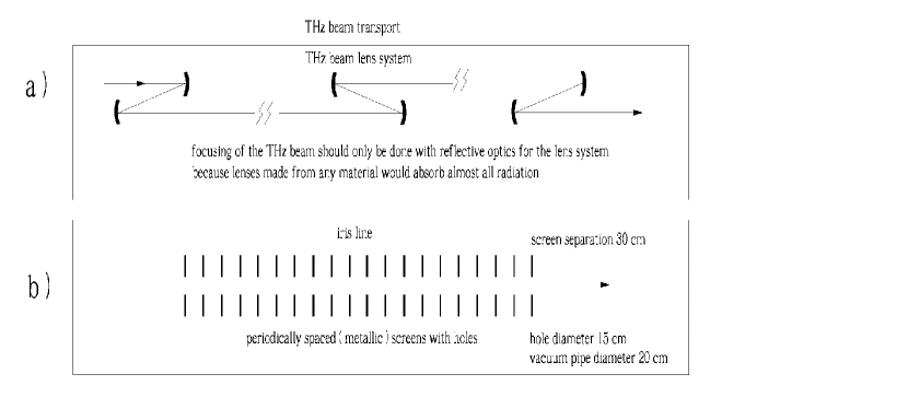
Focusing of the THz beam can only be provided with reflective optics since lenses made of any material would reflect and absorb all radiation at long distances. Fig. 1 (a) shows the optical arrangement of the transport system based on the use of a mirror guide. Each focusing unit is composed by two matched copper mirrors. The mirrors are separated in such a way that the incident angle is sufficiently small to minimize astigmatism. Existing mirror guides are characterized by a maximal length of about 40-60 m KULI , TIED . As discussed above, at European XFEL facility scientists need a beam transport system working for significantly longer distances, and the advantages of a mirror-guide based transport system are not evident.
In this paper we propose, as an alternative to the mirror line solution, to use an iris line, Fig. 1 (b). Iris lines are characterized by a low attenuation of the fundamental mode, self-filtering of high order modes, wide operational wavelength range and mechanical integrity of the structure. The first investigation of the influence of diffraction effects on the formation of the field eigenmodes in an iris line was carried out by Fox and Li using physical optics techniques FOX1 . A very different and mathematically solid approach to the same problem was introduced by Vainstein VAI1 , VAI2 . His studies are based on direct solution of Maxwell equations. An analysis of diffraction and reflection from the iris edges allowed Vainstein to derive for the first time analytic expressions for field distribution and mode losses in iris guides. An infinite, discrete set of eigenfunctions with corresponding complex eigenvalues can be found. This set of modes comprises leaky modes which are similar albeit not identical to modes of microwave waveguide with resistive walls. For instance, one can find that iris line modes, in contrast with microwave waveguide leaky modes, are independent of the polarization of the radiation.
Consider an axially symmetric iris guide with inner radius and distance between the two screens , and call the temporal Fourier transform of the transverse electric field of the radiation in the guide. Since the transverse size of the radiation is much larger than the reduced wavelength , the field envelope turns out to be a slowly varying function of the longitudinal coordinate with respect to the wavelength, and it obeys the paraxial Maxwell equation. Given the symmetry of the problem we can introduce polar coordinates , and seek a solution for the slowly varying field amplitude of given polarization component in the form
| (3) |
with n = 0, 1, 2, … . In the first order of the small parameter , where is the Fresnel number, the functions assume the form
| (4) |
where
| (5) |
with222 turns out to be related with one of the most famous mathematical functions, the Riemann zeta function . In fact, it is given by , see VAI1 , VAI2 . , and the -th root of the -th order Bessel function of the first kind (i.e. ). Substituting the expression for into the dispersion relation
| (6) |
we obtain the following expression for :
| (7) |
For the eigenmode with transverse wavenumber , the fraction of the radiation power losses per transit of one iris is given by
| (8) |
The relative loss of the -th mode of order after traveling for a distance is therefore given by
| (9) |
Due to the exponential dependence on , only the lower order modes tend to survive. Note that the exponent in Eq. (9) depends on the distance between two irises, , only weakly as , while there is a much stronger dependence on and .

As already mentioned, an iris line constitutes a suitable THz beam transport system for the European XFEL. For example, calculations indicate that the losses of the principal mode at m, cm and cm should be in the order of after traveling for a distance m. The transfer line pipe diameter is estimated to be cm. It is therefore technically feasible to install such transfer line inside the distribution tunnel XTD7. However, as discussed before, in order to efficiently couple radiation into the transmission line, one needs to match the spatial pattern of the source radiation to the mode of the transmission line.
Let us consider a coherent edge radiation source in the THz range, which is relatively simple to implement at the European XFEL. A setup where edge radiation is formed with the help of upstream and downstream metallic screens is shown in Fig. 2. The edge radiation from the upstream screen is extracted by the downstream screen, which acts as a mirror, and is sent to the iris transmission line. The length of straight section between upstream screen and mirror plays the role of the length of the insertion device for edge radiation (see for example oured for a review on these matters). The matching problem is easily solved if the THz source is equipped with an iris line as well 333A hole may be present in the edge radiation screens. A hole with a diameter of a few millimeters will not perturb the X-ray beam, nor the electron beam, nor the THz beam..
When dealing with a setup where THz radiation from an ultra relativistic electron beam is extracted by a mirror, one usually talks about Backward Transition Radiation (BTR). The main problem to solve is the specification of the electric field distribution at some position where the mirror is present. It should be stressed that the specification of the field at the mirror position must be considered as the first step to the specification of the field at the sample position. Such first step is considered separately, because the field at the mirror position is independent of the type of mirror and outcoupling optics. Once the field at the mirror position is known, the problem of specification of the field at the sample position can be solved for example with the help of Physical Optics techniques.
Let us discuss the problem of field characterization at the mirror position in more detail. When electrons are in unbounded space and come from an infinitely long straight line, the field distribution in the mirror plane can be calculated analytically following Ginzburg and Frank GINZ . In most practical cases, however, the Ginzburg-Frank equation is not applicable because two basic assumptions of the analytical derivation are not fulfilled: the electron beam is moving inside the metallic vacuum chamber, which effectively acts like an overmoded waveguide, and the straight line has a finite length with a bending magnet at the upstream end. It is known that Ginzburg-Frank theory is the limiting case of the more general theory of Edge Radiation in unbounded space. For a review on these matters see, among others, BOSC . For a very recent review on edge radiation and further references see, for example, SMOL . Emission of edge radiation in the presence of metallic boundaries has been a much less-treated subject in literature, compared to the unbounded space case. To the best of our knowledge, there is only one article reporting on edge radiation from electrons in a homogeneous metallic overmode waveguide, in particular with circular cross-section oured . The method described in oured is therefore capable of treating realistic experimental setups. In OURT we applied the method described in oured to the case of an iris guide444A very different approach for generating coherent THz radiation from ultra-relativistic ultrashort electron bunch in a vacuum chamber with specially introduced roughness was proposed in NOVA .
To fix ideas we focus our attention on the setup in Fig. 2. Electrons travel through the usual edge radiation setup. The difference is that now we account for the presence of the iris guide along the straight section. Since electrons pass through an upstream edge screen, one may assume that the iris guide starts at the upstream screen position. One should calculate the field distribution at the mirror position, which should be subsequently propagated to the experimental hall. The presence of an upstream edge screen seems at first glance not necessary, because electrons come in any case from the straight section. However, due to variations of the vacuum chamber cross-section upstream of the edge radiation setup, characterization of the field distribution at the upstream open-end of the iris guide is problematic. In spite of this, the electric field of the electron beam in the plane immediately behind the upstream screen can be well defined as zero, leading to extra simplifications. In this case we deal with a well-defined problem, and this allow us to characterize the field distribution at the end of the iris guide in the mirror plane.
In the case of the THz source at the European XFEL, the electron beam transverse size is much smaller than the diffraction size. This means that, as pertains the characterization of the THz pulses , the electron beam can be modeled as a filament beam. In this case the electron beam current is made up of moving electrons randomly arriving at the entrance of the iris guide, and obeying
| (10) |
where is the Dirac delta function, is the electron charge, is number of electrons in a bunch, and is the random arrival time of the -th electron at the undulator entrance. The electron bunch profile is described by the profile function . represents the probability of finding an electron between time and time . The beam current averaged over an ensemble of bunches can then be written in the form:
| (11) |
The radiation power at frequency , averaged over an ensemble, is given by the expression:
| (12) |
where is the radiation power from one electron and is the Fourier transform of the bunch profile function. For wavelengths shorter than the bunch length the form factor reduces to zero. For wavelengths longer than the bunch length it approaches unity.


Let us consider the practically important case of an electron bunch with non-Gaussian shape similar to that, which can be used to drive the European XFEL. Fig. 3 (left) shows the current distribution along the bunch. The nominal charge is nC. The electron bunch has a complicated shape, which is reflected in the square modulus of the form factor shown in Fig. 3 (right). In the case of the European XFEL, the squared of the bunch form factor modulus falls off rapidly for wavelengths shorter than mm. At the opposite extreme, the dependence of the form factor on the exact shape of the electron bunch is rather weak and can be ignored for wavelengths longer than mm.
We assume an electron beam moving along z-axis inside the axisymmetric iris line through the screens, Fig. 2. As already remarked, in reference OURT we developed a theory of such kind of THz source using Veinstein impedance boundary conditions and Green’s function approach to solve the field equations. We obtained the following expressions for the field at the mirror position:
| (14) | |||||
for the horizontal component and
| (16) | |||||
for the vertical one.
Here , is the relativistic factor, is the distance between upstream edge screen and mirror. Coherence is accounted through the form factor .
Only non-azimuthal symmetric modes turn out to be driven by the uniform motion of the space-charge distribution in the axisymmetric iris guide. From a physical view point this is a sound result. In fact, radiation is related with the energy change of particles, which takes place through the scalar product of the electric field and velocity of the particles. Since the transverse velocity is equal to zero in the edge radiation case, symmetric modes cannot lead to any energy change of the electrons moving along the axis of the axisymmetric iris guide. Let us focus on the fundamental non symmetric mode only. Neglecting losses, for the moment, the amplitude for the orthogonal polarization components of the field in a Cartesian coordinate system is given by
| (17) | |||
| (18) |
where is a constant for a certain longitudinal position, , and . It follows from these equations that the direction of the electric field is radial i.e. varies as a function of the transverse position. Therefore, for the edge radiation case we have two separate amplitudes for two orthogonal polarization directions. They are not azimuthal symmetric because they depend, respectively, on and , that is on the cosine and on the sine of the azimuthal angle. Only if one sums up the intensity patterns referring to the two polarization components one obtains the azimuthal symmetric intensity distribution

| (19) |
Edge radiation is characterized by broad spectrum and radial polarization. Many practical applications require control of the bandwidth and of the polarization of the THz pulse. The formation of the THz edge radiation pulse usually involves monochromatization and polarization filtering by wire-grid polarizer for producing linearly polarized THz radiation, Fig. 4.
Eq. (14) and Eq. (16) can be used as a basis to calculate the energy per unit spectral interval per unit surface
| (20) |
In our case of interest, the distance between sample and extracting mirror, , is much longer compared with the length of the edge radiation setup. Integrating over transverse coordinates over the iris hole, and assuming the energy of the radiation pulse at the sample position is given by OURT
3 Scheme for generating THz edge radiation at the European XFEL


The THz edge radiation source proposed in this paper is compatible with the layout of the European XFEL and can be realized with little efforts and minimal modifications to the baseline setup. The vacuum chamber equipped with iris line and outcoupling system can be installed in the unoccupied straight vacuum line upstream of the first electron beam dump, Fig. 5.
The transport of the THz beam to the experimental hall can be performed exploiting the use of the tunnel XTD7, as reproduced schematically in Fig. 5. The THz transmission line transporting the THz radiation introduces a path-delay of about 20 m with respect to the path of X-ray pulse from the SASE2 undulator. Since THz pump/X-ray probe experiments should be enabled, we propose to exploit the natural bunch spacing within a train, Fig. 6. The THz and X-ray pulses should be synchronized by a THz delay line installed in experimental hall, Fig. 7.
The THz transmission line includes at least ten -degrees turns, and will exploit plane mirrors as functional components. If the pipe of the transmission line has a diameter smaller than the distance between the irises it is possible to match incident and outgoing radiation without extra losses in these irregularities, Fig. 8.
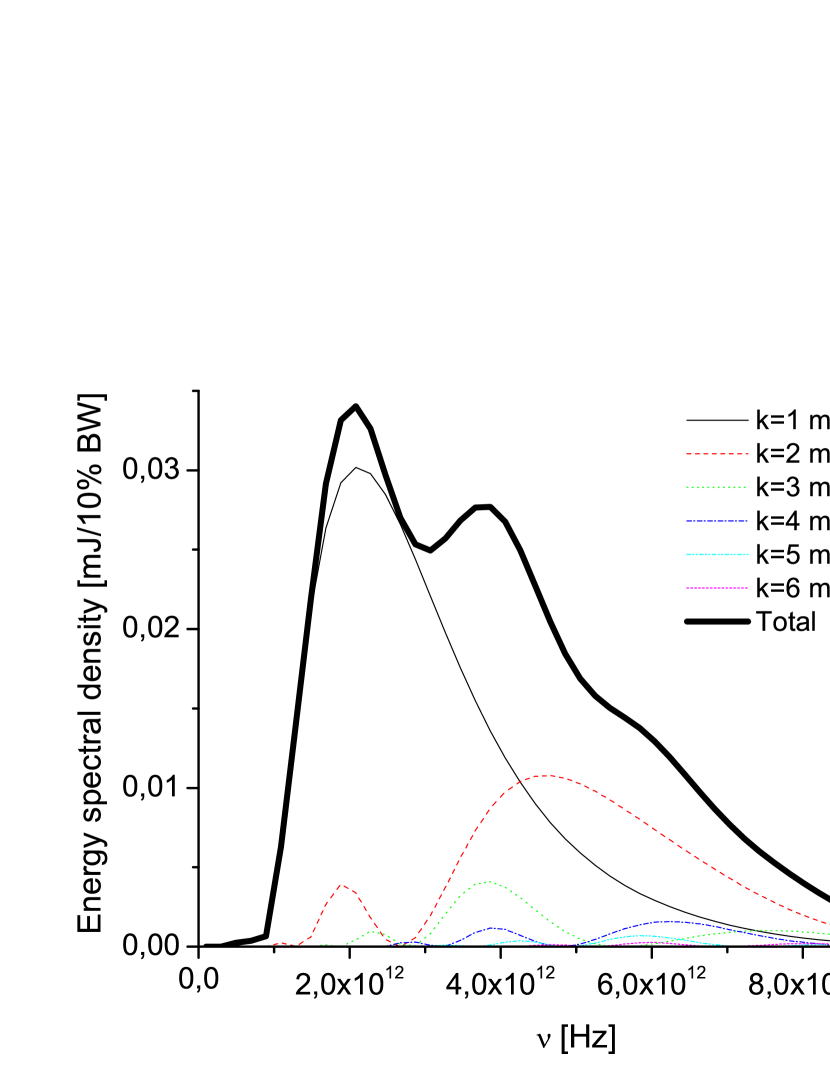
It is possible to calculate the energy spectral density at the sample position. The bunch form factor considered here is given in Fig. 3. We set a total length of the transport iris line of m. The energy losses in the line are accounted for. The energy spectral density at the exit of transport iris line as a function of the frequency is shown in Fig. 9. The curve is calculated with analytical formulas in Eq. (14), Eq. (16) and Eq. (20) including losses as in Eq. (9). The first four modes and the total are shown. Here , corresponding to 1 nC charge, cm, cm, m, and m.
The maximum value of the energy spectral density is achieved at m. When the bandpass filter is tuned to this value of , the expression for the total edge radiation pulse energy at the sample can be written in the form
| (23) |
The energy spectral density as a function of frequency exhibits a low frequency cutoff due to losses in the transport line and a high frequency cutoff due to electron bunch form factor suppression.
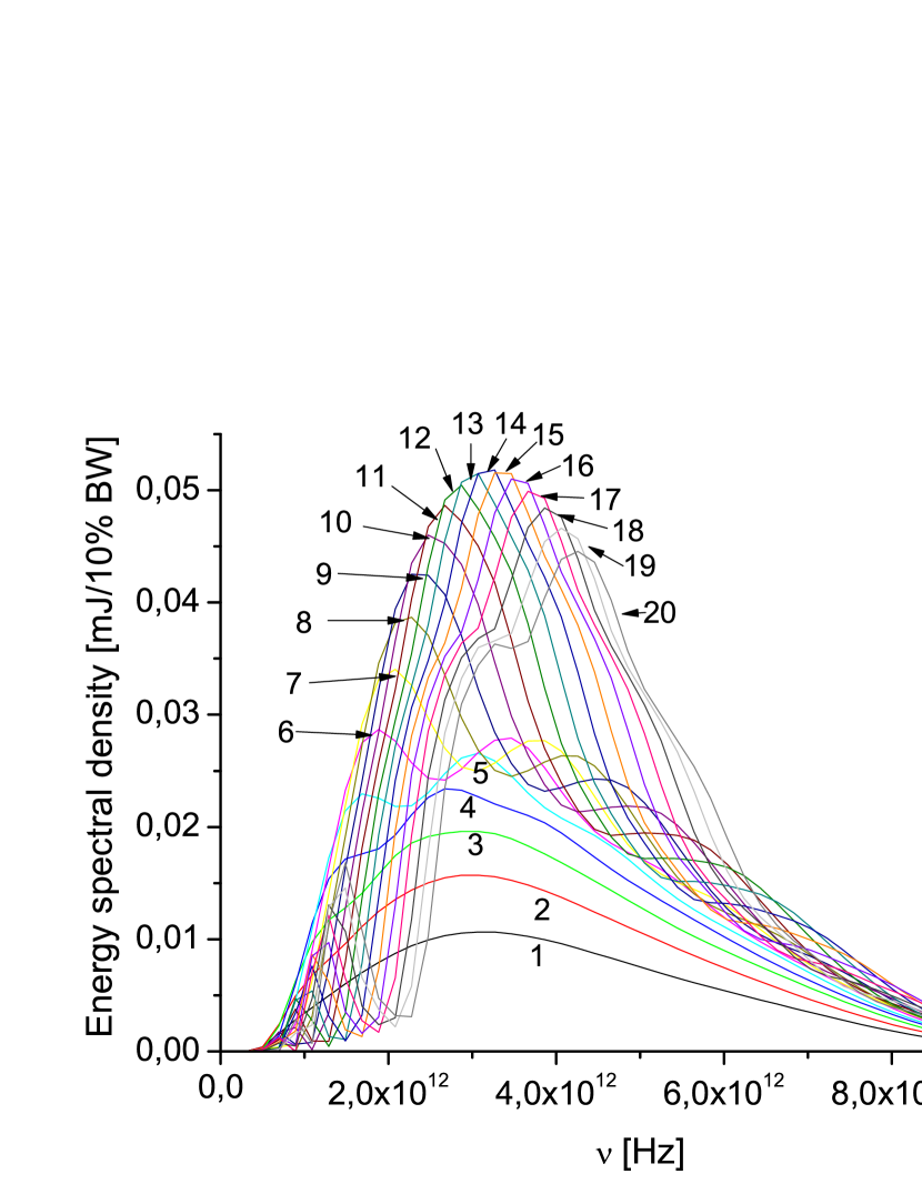
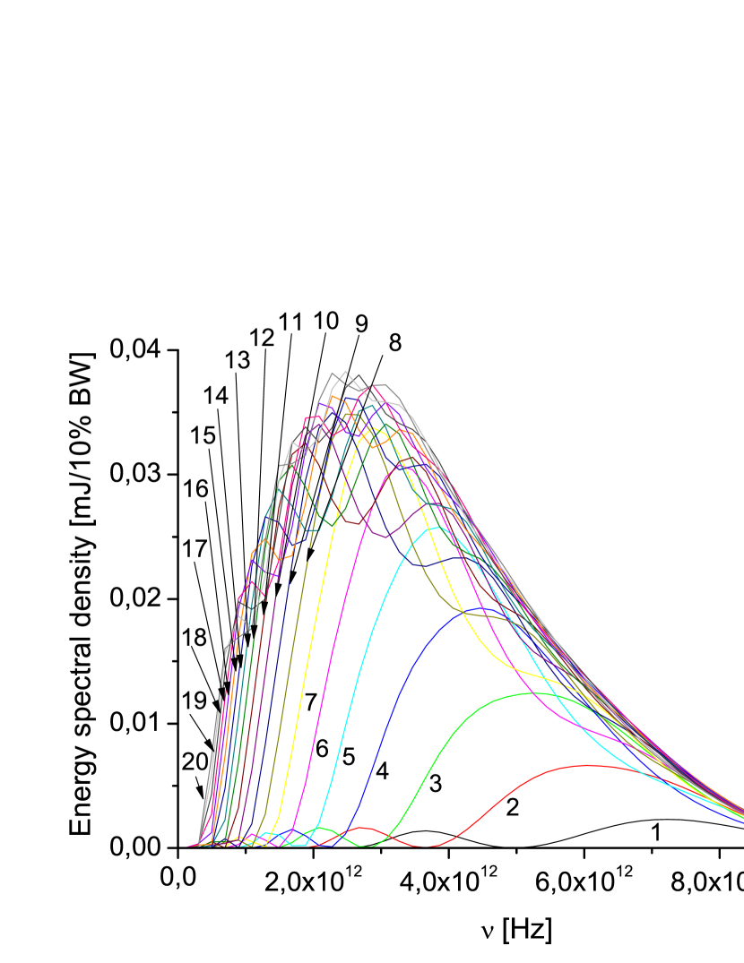
We studied the influence of the edge radiation setup length and of the iris hole radius on the operation of the THz source. Fig. 10 and Fig. 11 show the dependence of the THz pulse energy spectral density on the frequency for different values of these two parameters. The nontrivial behavior of the energy spectral density reflects the complicated parametric dependence in Eq. (22).
Finally, we note that according to our calculations in Fig. 9, one obtains about mJ total THz radiation pulse energy at the sample position at a wavelength around mm with a filter bandwidth . For one cycle in a pulse, corresponding to spectral bandwidth555Analysis of Eq. (7) shows that the phase velocity of the radiation field of the iris guide mode is larger than the velocity of light and depends on the frequency as for large values of the Fresnel number . In other words, the THz radiation pulse propagates through the transport line with a certain group velocity dispersion, and the shape of the envelope broadens. In our case of interest, the broadening is about , and can be neglected., one obtains about 0.5 GW peak power level. By highly focusing this THz beam, one will approach the high field limit of 1 V/atomic size.
4 European XFEL radiation parameters for THz pump/X-ray probe experiments
The electron beam formation system of the European XFEL accelerator complex operates with nominal charge of nC. The initially 2 mm (rms) long bunch is compressed in three magnetic chicanes by a factor of , and respectively, to achieve a peak current of kA.
The design of our THz source is also based on the exploitation of electron bunches with nominal charge of nC. However, in order to optimize the THz source performance, the electron bunch should be made about two times shorter than in the nominal mode of operation. In this case, the peak current increases by a factor two. Operation beyond the design parameters leads to some degradation of the electron beam quality. The operation of the proposed THz source is insensitive to the emittance and energy spread of the electron bunch. However, one should examine the performance of the electron bunches in terms of X-ray SASE pulses generation, since THz pump/X-ray probe experiments are based on such pulses.


First, we ran start-to-end simulations for the beam formation system ZAGO , yielding the beam characteristics summarized in Fig. 12 in terms of current, emittance, energy and energy spread distribution along the electron bunch at the entrance of the SASE2 undulator. Subsequently, we studied the performance of the electron bunch with the help of the FEL code GENESIS 1.3 GENE running on a parallel machine. Here we will present results based on a statistical analysis consisting of runs.

Fig. 13 shows the evolution of the rms horizontal beam size as a function of the distance inside the SASE2 undulator. The figure shows the evolution for the position of maximal current in the bunch.
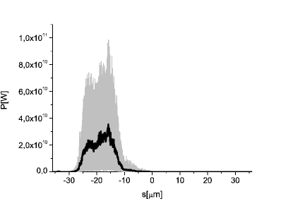
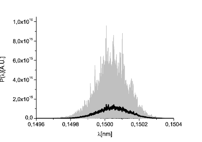
The SASE2 undulator is composed of cells. The SASE output after the first undulator cells is shown in Fig. 14. On the left plot we show the output power, while on the right plot one can see the spectrum around the the fundamental at Angstrom. Grey lines refer to single shot realizations, the black line refers to the average over a hundred realizations. The output characteristics are in line with the expected baseline performance, demonstrating an average power of several tens of GW, and a relative bandwidth in the range.


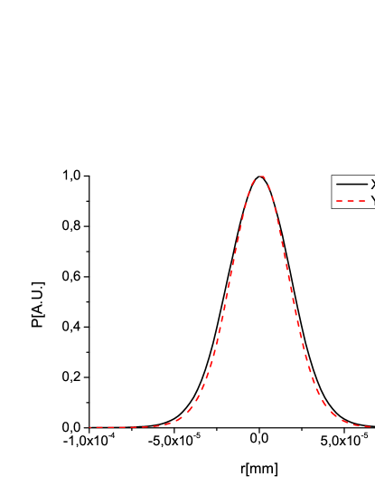
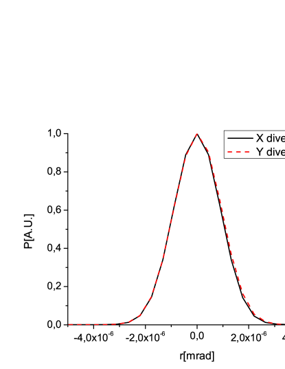
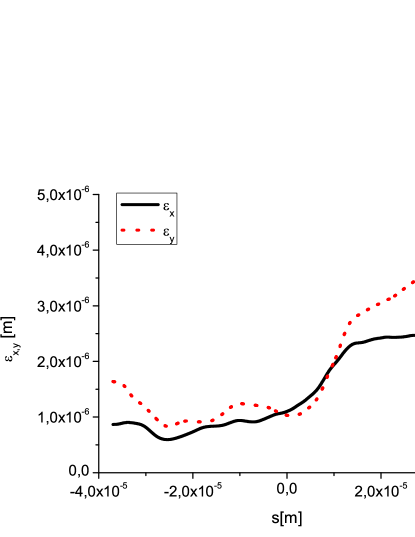
The left plot in Fig. 15 shows the evolution of the pulse energy as a function of the position inside the SASE2 undulator, while the right plot shows the variance of the energy fluctuations. As usual, fluctuations increase in the linear regime, and drop at saturation. Finally, in Fig. 16 we present the transverse profile of the radiation distribution, obtained by averaging over the statistical ensemble and the directivity diagram of the radiation, obtained by Fourier transformation. Fig. 16 demonstrates a spot size of several tens of microns, and a divergence of a few microradians.
Simulations presented in this Section show that the operation of SASE2 with a nC bunch and a peak-current increase of a factor two compared to the nominal mode of operation (also with a nC bunch but with design parameters), leads practically to the same peak power of the X-ray pulse that is in the order of GW. In other words, the two times shorter bunch duration in our case study has the simple consequence of a decrease in the X-ray pulse energy of about a factor two, from around mJ in the design case to around mJ in our case.
5 Conclusions
The accelerator complex at the European XFEL will produce ultrashort electron bunches approaching sub-hundred fs duration. It is natural to take advantage of these ultra-short bunches to provide coherent THz radiation. THz radiation pulses can be generated by the spent electron beam downstream of X-ray undulators. Any method relying on the spent electron beam at the European XFEL should also provide, at the same time, a way of transporting the radiation up to experimental hall for a distance in the -meters range.
Transmission of the THz beam can only be accomplished with quasi- optical techniques. For the European XFEL case we propose to use an open beam waveguide such as an iris guide. In order to efficiently couple radiation into the iris transmission line, it is desirable to match the spatial pattern of the source radiation to the propagating mode of the transmission line. To solve the matching problem, we propose to generate the THz radiation directly within the iris guide. The resulting electric field is found as superposition of the iris waveguide modes, and is studied for the parameters case of the European XFEL. We demonstrated that the maximally achievable field strength at the sample is in the high field region of 1 V/atomic size.
The present design describes a basic option for a THz source at the European XFEL facility. A technical solution allowing for significant performance enhancement of the output, of about an order of magnitude, without significant changes of the baseline hardware, seems also feasible. Such solution consists in the extension of the proposed method to a higher charge mode of operation (up to nC), which is within the possibilities of the European XFEL accelerator complex. It is hoped that future research may extend the THz source performance to a few GW power level.
6 Acknowledgements
We are grateful to Massimo Altarelli, Reinhard Brinkmann, Serguei Molodtsov, Thomas Tschentscher and Edgar Weckert for their support and their interest during the compilation of this work.
References
-
[1]
The LCLS-II Conceptual design report,
https:slacportal.slac.stanford.
edusites lclspubliclclsiiPublishedDocumentsCDR20Index.pdf - [2] J. N. Galayda, Z. Huang and P.A. Heimann Proceedings of 2011 PAC, New York, NY, USA, TUOBS1 (2011).
- [3] Z. Wu, et al., Proceedings of the 2011 PAC Conference, New York, NY, USA, MOP071 (2011).
- [4] A. S. Fisher et al. ”Terahertz pump and X-ray probe development at the LCLS”, TUPB22, Proceedings of the 33rd FEL Conference, Shanghai, China (2012).
- [5] M. Altarelli, et al. (Eds.) XFEL, The European X-ray Free-Electron Laser, Technical Design Report, DESY 2006-097, Hamburg (2006).
- [6] G. Geloni, V. Kocharyan and E. Saldin, ”Scheme for generating and transporting THz radiation to the X-ray experimental floor at the LCLS baseline”, DESY 11-134 (2011), http://arxiv.org/abs/1108.1085.
- [7] A. G. Fox and T. Li, Bell syst. Tech. J. 40. 453 (1961).
- [8] L. A. Vainstein, ”Open resonators for lasers” Sov. Phys. JETP, vol. 17, pp 709-719.
- [9] L. A. Vainstein (also Anglicized as Weinstein), Open Resonators and Open Waveguides, Colem Press, 1969.
- [10] G. Geloni et al. NIM A 605,3, 409 (2009) and NIM A 607,2, 470 (2009), and ”Theory of edge radiation” DESY 08-118, http:arxiv.orgabs0808.1846.
- [11] V.L. Ginzburg and I.M. Frank, Soviet Phys. JETP 16. 15 (1946)
- [12] R.A. Bosch, Il Nuovo Cimento 20 4 (1998) 483 .
- [13] N. Smolyakov, in ”Electromagnetic Radiation”, edited by S.O. Bashir, ISBN 979-953-307-332-2
- [14] G. Goubau and F. Schwering, ”On the guided wave propagation of electromagnetic wave beams” IEEE Trans. Microwave Theory Tech., vol. 9, pp. 248-256, Mar. 1961.
- [15] J. E. Christian and G. Goubau, ”Some measurements on an iris beam waveguide” Proc. IEEE, vol. 49, pp. 1679-1680, Nov. 1961.
- [16] B. Z. Katsenelenbaum, ”Transmission of mm waves by reflection from a series of focusing reflectors” Radio Eng. Electron. Phys., no. 9, p. 1446, 1963
- [17] J. E. Degenford, M. D. Sirkis, and W. H. Steier, ”The reflecting beam waveguide” IEEE Trans. Microwave Theory Tech., vol. 12, pp. 445-453, Jul. 1964
- [18] M. Sorolla, R. Martin et al., ”Beam waveguide for ECRH at TJ-II” International Journal of Infrared and Millimiter Waves, Vol. 18, No. 6, pp. 1161-1168, 1997
- [19] A. Fernandes et al., ”Quasioptical transmission lines for ECRH at TJ-II Stellarator” International Journal of Infrared and Millimiter Waves, Vol. 21, no. 12, pp.1945-1957, 2000.
- [20] G. N. Kulipanov et al., Terahertz Science and Technology, Vol. 1, No . 2, pp. 107, June 2008
- [21] K. Tiedtke et al.,New Journal of Physics 11 (2009) 023029
- [22] A. Novokhatski, M. Timm and T. Weiland ”A proposal for the surface roughness wake field measurement at the TESLA test facility”, Proceedings of the PAC 1999, p.2879 (1999).
- [23] I. Zagorodnov, M. Dohlus, Phys. Rev. STAB, 14, 014403 (2011).
- [24] S Reiche et al., Nucl. Instr. and Meth. A 429, 243 (1999).