Dispersion in media containing resonant inclusions: where does it come from?
Abstract
We study the propagation of waves in a quasi 1D homogeneous host medium filled with various resonators. We first prove that a far field coupling between the elements explains its dispersive nature. This coupling is interpreted as a Fano interference between the incoming wave and the waves re-radiated by each resonator, which experience a phase shift at resonance. We propose a simple formalism that gives the complete dispersion relation of the medium in terms of the far field response of a single resonator. We prove that our approach applies to and unifies various domains such as metamaterials, hybridization band gap materials and designer’s plasmons. Finally we show that those media, spatially random or organized on a scale larger than the wavelength, also present very interesting properties, which broadens the range of man made exotic materials.
Propagation media containing resonant inclusions have been studied for over a century in acoustics, electromagnetism or solid state physics. There exist some in nature, such as dielectrics, which contain enormous amounts of atoms. To calculate those materials permittivities one considers that each atom “sees” the same electromagnetic field and calculates the average field that takes into account an incoming wave as well as the overall response of the ensemble of atoms Feynman et al. (1964). This macroscopic view assumes that there are no variations of the electromagnetic field at the scale of the inter-atomic distance. Later on, the concept of polariton has been proposed to explain the propagation of electromagnetic waves in dielectrics Hopfield (1958); Lagendijk (1993). The polariton approach of the index of refraction in dielectrics relies on mostly absorptive scattering and comes down to the original effective medium one Lagendijk (1993).
There has been a renewed interest in systems consisting in arrays of resonators in a host medium since the last decade, notably owing to the emergence of metamaterials Engheta and Ziolkowski (2006); Cai (2010). Even though many metamaterials now rely on non resonant unit cells Pendry et al. (2006); Leonhardt (2006), we abusively ignore them here when mentioning metamaterials. John Pendry, who first proposed metamaterial presenting electric and magnetic activities in electromagnetism Pendry et al. (1996, 1999), adopted a macroscopic point of view and developed an approach based on field averaging to obtain the overall response of the resonators and the effective properties of those man made materials Engheta and Ziolkowski (2006); Cai (2010). In this formalism the period of the considered medium ought to be much smaller than the free space wavelength. Nowadays those materials are commonly studied from the far field which precludes any knowledge of the field at the unit cell level, and mostly to design media with negative index Pendry (2000); Veselago (1968); Smith et al. (2000).
In the meantime, mainly in acoustics, there has been a large interest for materials presenting hybridization band gaps Liu et al. (2000); Cowan et al. (2011); Lee and Page (2009); Still et al. (2008); Psarobas et al. (2002); Leroy et al. (2009); van Coevorden et al. (1996); Chong et al. (2007). The latter, contrary to conventional photonic or phononic crystals Yablonovitch (1987); Sukhovich et al. (2008, 2009); Joannopoulos et al. (2008), present stop bands that are related to the resonant nature of the unit cell rather than the period of the medium. This phenomenon occurs when a resonator hybridises with the continuum of the plane waves of a homogeneous medium, giving rise to a binding and an anti-binding branches, that are separated by the so-called hybridization band gap Cowan et al. (2011). This effect is usually rather elusively justified by a level repulsion between the wave (the photon or the phonon), and a local resonance Cowan et al. (2011). Interestingly similar structures have been proposed to decouple antennas Yang and Rahmat-Samii (2003); Sievenpiper et al. (1999) and are named electromagnetic band gap materials (EBG).
At this stage, one could wonder if we are not dealing with the same physical phenomenon albeit named differently. Metamaterials and hybridization based materials are indeed both obtained when a homogeneous medium is filled with resonant elements and they both present bands of permitted and prohibited propagation. There are, however, drastic differences in the common understanding of those phenomena. Because of the deep subwavelength nature of metamaterials, their effective parameters and bandwidth are usually justified by a strong near field coupling between the elements Engheta and Ziolkowski (2006); Cai (2010). On the contrary, hybridization effects suppose solely a coupling between free space waves and a single resonant element. One question arises: are those phenomena identical, and if so, where does dispersion come from in those materials?
In this letter, we use a very simplified model in order to grasp the physics of an array of resonators in a homogeneous medium. We first prove that, to a large extent, the response of a quasi 1D medium is governed by a far field coupling between the individual elements. This coupling can be understood as Fano interferences Fano (1961); Miroshnichenko et al. (2010) between the incoming plane waves and the field reemitted by the resonators. We give a phenomenological description of this effect in terms of the frequency response of an oscillator. We propose a simple formalism that gives the dispersion relation of quasi 1D metamaterials using solely the far field transmission coefficient of a single unit cell and the period of the medium. We verify our approach and the obtained formalism on various media including random and wavelength scaled ones.
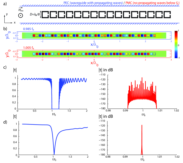
Our first goal is to identify the type of coupling that can give rise to an effective negative property in a metamaterial. To that aim, we study numerically a very simple system consisting in an array of 40 split ring resonators (SRR) made of perfect electric conductor (PEC) and placed in a waveguide of subwavelength width. The SRR resonate around for transverse magnetic polarized (TM) waves and have a square shape /9 wide. Such a system is known to present a negative permeability. We perform the simulation in a 2D domain, and hence our approach is quasi 1D (Fig. 1.a.). Because we want to separate near field contribution from far field ones, we simulate the structure with two types of waveguides: the first has PEC boundaries and hence no cutoff for the impinging TM waves, while the second has perfect magnetic conductor (PMC) boundaries meaning that the impinging waves are evanescent along the waveguide. This way we can select which coupling we allow: near field only for PMC or near and far field couplings for PEC. In Figure 1.b, we map the magnetic field in the array of SRR for two different frequencies and for the PEC and PMC waveguides. Both show subwavelength varying patterns correspondent to a high effective index of refraction. More interesting are the plots of the transmission coefficients presented in Figure 1.c for the two studied cases. For the PMC waveguide, which forbids any far field type of coupling between the resonators, the modes of the system are symmetrically positioned around the resonance frequency of a single SRR on a narrow spectral range. This type of branch is typical of the tight-binding model commonly used in solid state physics Kittel (1996) or coupled resonators optical waveguides (CROWs) Yariv et al. (1999), and cannot explain neither the effective negative permeability of the array of SRR, nor any band gap. On the contrary, the transmission coefficient of the PEC waveguide structure displays the wanted features: it is highly asymmetric, shows a wide band of propagating modes below and a wide stop band above. The band of propagating modes can be seen as a high permeability one, and the band gap as a negative permeability window. However another interpretation can be given. Above the band gap, another set of modes seem to be observable from the transmission coefficient. This band, well known for materials presenting hybridization band gaps, is the anti-binding one, while that of the lower frequency and high wavenumber modes is the binding one. Those two branches are separated by a hybridization band gap. The response of this system can hence be explained by an hybridization between the resonance of a SRR and the continuum of free space waves.
From here two consequences appear. First, in order to obtain the expected properties of an array of SRR, one must take into account the far field coupling between the resonators. Second, this system, a 1D metamaterial, can be interpreted through the prism of hybridization. In order to obtain a deeper insight of the coupling involved, we simulate the response of a single resonator placed in the same waveguides. The transmission coefficients obtained are plotted in Figure 1.d. For the PMC case, the latter displays a symmetric shape consistent with a resonant tunneling of the electromagnetic energy at the resonance of the SRR. When the waveguide has PEC boundary conditions, the transmission coefficient has a singular profile since it presents a maximum of transmission right before the resonance and a minimum slightly after: this is typical of a Fano profile Fano (1961); Miroshnichenko et al. (2010).
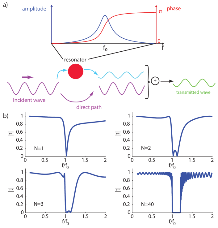
We prove now that Fano interferences explain the coupling between the resonators and its far field nature. The principle, schematised in Figure 2.a, can be explained in the following way. The resonator placed in the propagating waveguide scatters the incoming plane wave. Around resonance, the resonator accumulates energy and re-radiates waves which interfere with the unscattered incoming plane waves. Now the phase of the field in the oscillator changes abruptly at the resonance from 0 to , meaning that its contribution can interfere constructively with the incoming plane waves or destructively. This explains the Fano profile and gives a very interesting information; since the resonator experiences a phase shift at the resonance, it can “give” some extra phase to the incoming plane wave, but it can also drastically suppress its transmission through destructive interferences Not .
The principal features of the array of SRR can be inferred quite straightforwardly from this approach. On one hand, before resonance, the extra phase that originates from the resonators can compensate for the small phase shift accumulated through propagation over a unit cell, meaning that the field in the array can vary on scales as small as its period, hence leading to a high effective permeability. On the other hand, after resonance, the SRR respond in anti-phase and cancel the incoming plane wave which results in an hybridization band gap or equivalently an effective negative permeability.
Going from one resonator to an array, the effect of Fano type interferences are cumulative. In Figure 2.b, we plot the transmission coefficients of 1, 2, 3 and 40 SRR. The number of transmission maxima and minima equals the number of resonators on each branch. Each resonator gives rise to a Fano interference in the spectrum created by the previous one. This has two consequences; first, it widens the band of high or negative effective permeability. Second, a system of N resonators supports 2N modes with distinct resonant frequencies, N on the binding branch and N on the anti-binding branch. Again, this differs from a tight-binding model, which gives only N modes symmetrically positioned around the resonant frequency . Naturally, an infinite system supports a continuum of modes resulting from a continuum of Fano interferences. Hence, the coupling between the resonators can be understood simply in terms of Fano interferences of far field components of the spatial spectrum.
We now utilize the formalism of the transfer matrix Yariv and Yeh (1984) in order to obtain the dispersion relation of a linear array of resonators that are coupled through propagating waves only. To do so, we perform calculations very similar to those done on CROWs Yariv et al. (1999); Xu et al. (2000) and obtain a relation of the form Sup :
| (1) |
where is the wavenumber in the medium, is the period of the medium and is the complex far field transmission coefficient of a single unit cell.
This formula gives both the wavenumber of the propagating modes supported by an array of resonator, but also the attenuation coefficient in the hybridization band gaps. We first verify its validity by numerically studying various types of resonators. Our simulations are lossless and all dimensions are given relatively to the wavelength at the first resonance of the considered unit cell . We study the response to a plane wave of an array of 40 resonators in a waveguide. We simulate first a linear array of subwavelength SRR (Fig. 3.a). Then we apply our approach to Mie resonators, that is, squares of n10 dielectric material (Fig. 3.b). We also simulate using acoustic waves the soda cans, that is the Helmholtz resonators, used in Lemoult et al. (2011a), this time using a 3D waveguide (Fig. 3.c). Finally we study /4 high, infinitely long slits in PEC, a building block of designer’s plasmons Pendry et al. (2004); Garcia-Vidal et al. (2005) (Fig. 3.d). We calculate the spatial spectrum of the electromagnetic or acoustic fields in those structures at each frequency and map the dispersion relations Figure 3.a-d. Meanwhile, we simulate each resonator independently in a waveguide and obtain its complex far field transmission coefficient. We superpose on the maps our theoretical dispersion relation and plot the calculated attenuation coefficients in the gaps using equation 1.
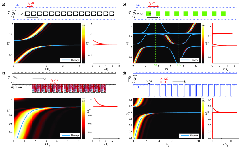
Figure 3 shows that for every medium under study, our simple formalism, based on propagating waves only, exactly reproduces the dispersion relation obtained by rigorously simulating the entire structure. This means that those structures, although organized on a deep subwavelength scale, are coupled mostly through propagating waves. Furthermore, one each structure gives rise to a wide and efficient hybridization band gap. For each medium, the frequency separates the propagating modes and the hybridization band gap, which justifies the phenomenological explanation given above Not . This means that all those quasi 1D materials have in common a unique physical basis: an hybridization between the resonator and the propagating waves. This approach permits to unify several distinct ones. For instance designer’s plasmons Pendry et al. (2004); Garcia-Vidal et al. (2005); Maier et al. (2001), which are all based on a resonant unit cell, can be analysed under the same prism than negative permeability Pendry et al. (1999), permittivity Huang et al. (2004); Shapiro et al. (2006); Felbacq and Bouchitt (1997) or Young’s modulus materials Liu et al. (2000); Fang et al. (2006); Zhang et al. (2009). This is in agreement with the fact that an interface between a negative and a positive effective property medium supports surface waves Shapiro et al. (2006); Ambati et al. (2007) which we utilized in order to beat the diffraction limit from the far field Lemoult et al. (2011a, b, c, 2010).
From these results, it is clear that near field couplings play a very little role in the dispersion observed in the systems studied here. This leads us to ask the following question: does one need to fulfill the effective medium condition of a deep subwavelength period in order to design media with interesting properties? To answer this question and demonstrate the possibilities offered by this Fano interference type of coupling, we present additional simulations. We want to demonstrate that hybridization band gaps, or equivalently bands of negative effective properties, exist even when the spacing between the resonators is increased and resist to disorder. To that aim we simulate four more systems. The first one consists in an array of SRR separated by /2.4, a distance comparable to the period of typical Bragg crystals (Fig. 4.a). Similarly we study a /1.7 periodic array of dielectric squares of index n10 (Fig. 4.b). We simulate a chain of randomly positioned SRR (average period a of /5, Fig. 4.c). Finally we study an array of Mie resonators of period of (Fig. 4.d). Again we use equation 1 to superpose our theoretical dispersion relations and plot accordingly the attenuation coefficient in the band gaps. Those curves totally fit the simulations.
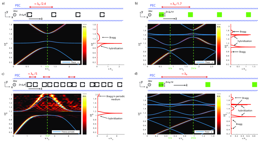
Figure 4 shows a very important feature common to all studied media: there exist in all the dispersion relations bands of propagation and hybridization band gaps regardless of the medium’s order or period, thanks to the far field coupling between the resonators. Their positions, however, can be shifted due to the combined effects of interferences in between the unit cells and the resonant nature of the latter. Nevertheless, this proves that material made of resonant unit cells, even spaced by distances of the order or larger than the wavelength or random, can present negative effective properties.
Figure 4 also proves that Bragg bands and band gaps coexist with hybridization dilute systems, as was already proved in Cowan et al. (2011); Lee and Page (2009); Still et al. (2008); Psarobas et al. (2002); Leroy et al. (2009), hence providing an even greater flexibility for designing materials with unusual properties. Due to their resonant nature, hybridization band gaps are much more efficient than Bragg ones. Mixing Bragg and hybridization effects could possibly lead to very interesting new phenomena.
We note that disorder plays a different role for Bragg and hybridization types of bands. Indeed, in Figure 4.c, which shows the results of an array of SRR randomly positioned, the Bragg band gap has disappeared, while the hybridization one remains, a fact demonstrated in the past in acoustics Cowan et al. (2011); Lee and Page (2009); Still et al. (2008); Psarobas et al. (2002); Leroy et al. (2009). This underlines the potential applications of hybridization band gaps in the visible.
This work finally appeals some concluding remarks. We have shown here that dispersion in arrays of resonators can be understood in terms of a far field type of coupling between the elements that arise from Fano interferences between the incoming waves and the waves re-radiated by the resonators. This approach gives a physical mechanism to the hybridization effect often referred to in acoustics and applies to metamaterials, locally resonant materials, designers plasmons and EBG structures. It demonstrates that wide bandwidth negative effective properties or hybridization gaps do not require any near field coupling and exist in random and wavelength scaled media. We believe that mixing Bragg and hybridization effects makes the physics of man made materials even richer and their properties more flexible. We underline however that some materials based on resonant unit cells can be also coupled through near field interactions, such as inductive or capacitive couplings in electromagnetics. This is typically the case for closely spaced SRR in 2D or 3D which can support magneto-inductive waves Sydoruk et al. (2009), or bubbles in acoustics Leroy et al. (2009, 2008). Such near field coupling may be taken into account in our formalism, but this is out of the scope of this paper. Our approach requires a generalization to 2D and 3D materials. This could permit to design materials with exotic properties quite simply. Initial results on our experimental system of Lemoult et al. (2011a) support our intuition that 2D or 3D systems behave exactly as the 1D one studied here. This suggests that since the Fano based dispersion in those media is linked to the forward scattering cross-section of the individual resonators, metamaterials are inherently non-local. Finally this idea should be transposable to all systems that support waves and contain resonant inclusions, which are very common in nature.
The authors acknowledge fundings from Orange Labs, and F. Lemoult acknowledges funding from French ”Direction Générale de l’Armement”.
References
- Feynman et al. (1964) R. P. Feynman, R. B. Leighton, M. Sands, et al., The Feynman lectures on physics, Vol. 2 (Addison-Wesley Reading, 1964).
- Hopfield (1958) J. J. Hopfield, Phys. Rev. 112, 1555 (1958).
- Lagendijk (1993) A. Lagendijk, Ultrashort processes in condensed matter 314, 197 (1993).
- Engheta and Ziolkowski (2006) N. Engheta and R. Ziolkowski, eds., Metamaterials: physics and engineering explorations (John Wiley & Sons & IEEE Press, 2006).
- Cai (2010) S. V. Cai, Wenshan, Optical metamaterials - Fundamentals and applications (Springer Berlin / Heidelberg, 2010).
- Pendry et al. (2006) J. B. Pendry, D. Schurig, and D. R. Smith, Science 312, 1780 (2006).
- Leonhardt (2006) U. Leonhardt, Science 312, 1777 (2006).
- Pendry et al. (1996) J. B. Pendry, A. J. Holden, W. J. Stewart, and I. Youngs, Phys. Rev. Lett. 76, 4773 (1996).
- Pendry et al. (1999) J. B. Pendry, A. J. Holden, D. J. Robbins, and W. J. Stewart, IEEE Transactions on Microwave Theory and Techniques 47, 2075 (1999).
- Pendry (2000) J. B. Pendry, Phys. Rev. Lett. 85, 3966 (2000).
- Veselago (1968) V. G. Veselago, Physics-Uspekhi 10, 509 (1968).
- Smith et al. (2000) D. R. Smith, W. J. Padilla, D. C. Vier, S. C. Nemat-Nasser, and S. Schultz, Phys. Rev. Lett. 84, 4184 (2000).
- Liu et al. (2000) Z. Liu, X. Zhang, Y. Mao, Y. Y. Zhu, Z. Yang, C. T. Chan, and P. Sheng, Science 289, 1734 (2000).
- Cowan et al. (2011) M. L. Cowan, J. H. Page, and P. Sheng, Phys. Rev. B 84, 094305 (2011).
- Lee and Page (2009) E. J. S. Lee and J. H. Page, in Proceedings of Symposium on Ultrasonic Electronics, Vol. 30 (2009) pp. 461–462.
- Still et al. (2008) T. Still, W. Cheng, M. Retsch, R. Sainidou, J. Wang, U. Jonas, N. Stefanou, and G. Fytas, Phys. Rev. Lett. 100, 194301 (2008).
- Psarobas et al. (2002) I. E. Psarobas, A. Modinos, R. Sainidou, and N. Stefanou, Phys. Rev. B 65, 064307 (2002).
- Leroy et al. (2009) V. Leroy, A. Bretagne, M. Fink, H. Willaime, P. Tabeling, and A. Tourin, Appl. Phys. Lett. 95, 171904 (2009).
- van Coevorden et al. (1996) D. V. van Coevorden, R. Sprik, A. Tip, and A. Lagendijk, Phys. Rev. Lett. 77, 2412 (1996).
- Chong et al. (2007) Y. D. Chong, D. E. Pritchard, and M. Soljačić, Phys. Rev. B 75, 235124 (2007).
- Yablonovitch (1987) E. Yablonovitch, Phys. Rev. Lett. 58, 2059 (1987).
- Sukhovich et al. (2008) A. Sukhovich, L. Jing, and J. H. Page, Phys. Rev. B 77, 014301 (2008).
- Sukhovich et al. (2009) A. Sukhovich, B. Merheb, K. Muralidharan, J. O. Vasseur, Y. Pennec, P. A. Deymier, and J. H. Page, Phys. Rev. Lett. 102, 154301 (2009).
- Joannopoulos et al. (2008) J. D. Joannopoulos, S. G. Johnson, J. N. Winn, and R. D. Meade, Photonic Crystals: Molding the Flow of Light (Second Edition) (Princeton University Press, 2008).
- Yang and Rahmat-Samii (2003) F. Yang and Y. Rahmat-Samii, Antennas and Propagation, IEEE Transactions on 51, 2936 (2003).
- Sievenpiper et al. (1999) D. Sievenpiper, L. Zhang, R. Broas, N. Alexopoulos, and E. Yablonovitch, IEEE transactions on microwave theory and techniques 47, 2059 (1999).
- Fano (1961) U. Fano, Phys. Rev. 124, 1866 (1961).
- Miroshnichenko et al. (2010) A. E. Miroshnichenko, S. Flach, and Y. S. Kivshar, Rev. Mod. Phys. 82, 2257 (2010).
- Kittel (1996) C. Kittel, Introduction to Solid State Physics (New York, Wiley, 1996).
- Yariv et al. (1999) A. Yariv, Y. X., R. K. Lee, and A. Scherer, Opt. Lett. 24, 711 (1999).
- (31) This depends on the scattering cross section of the resonator. For isotropic ones, the propagation band is before the resonant frequency and the gap after, for dipolar one it goes opposite. A more detailled study containing this analysis will be published elsewhere .
- Yariv and Yeh (1984) A. Yariv and P. Yeh, Optical Waves in Crystals (New York, Wiley, 1984).
- Xu et al. (2000) Y. Xu, Y. Li, R. K. Lee, and A. Yariv, Phys. Rev. E 62, 7389 (2000).
- (34) See the supplementary information .
- Lemoult et al. (2011a) F. Lemoult, M. Fink, and G. Lerosey, Phys. Rev. Lett. 107, 064301 (2011a).
- Pendry et al. (2004) J. B. Pendry, L. Martin-Moreno, and F. J. Garcia-Vidal, Science 305, 847 (2004).
- Garcia-Vidal et al. (2005) F. J. Garcia-Vidal, L. Martin-Moreno, and J. B. Pendry, Journal of Optics A: Pure and Applied Optics 7, S97 (2005).
- Maier et al. (2001) S. A. Maier, M. L. Brongersma, and H. A. Atwater, Appl. Phys. Lett. 78, 16 (2001).
- Huang et al. (2004) K. C. Huang, M. L. Povinelli, and J. D. Joannopoulos, Applied Physics Letters 85, 543 (2004).
- Shapiro et al. (2006) M. A. Shapiro, G. Shvets, J. R. Sirigiri, and R. J. Temkin, Opt. Lett. 31, 2051 (2006).
- Felbacq and Bouchitt (1997) D. Felbacq and Bouchitt , Waves in Random Media 7, 245 (1997).
- Fang et al. (2006) N. Fang, D. Xi, J. Xu, M. Ambati, W. Srituravanich, C. Sun, and X. Zhang, Nature materials 5, 452 (2006).
- Zhang et al. (2009) S. Zhang, L. Yin, and N. Fang, Phys. Rev. Lett. 102, 194301 (2009).
- Ambati et al. (2007) M. Ambati, N. Fang, C. Sun, and X. Zhang, Phys. Rev. B 75, 195447 (2007).
- Lemoult et al. (2011b) F. Lemoult, M. Fink, and G. Lerosey, Waves in Random and Complex Media 21, 591 (2011b).
- Lemoult et al. (2011c) F. Lemoult, M. Fink, and G. Lerosey, Waves in Random and Complex Media 21, 614 (2011c).
- Lemoult et al. (2010) F. Lemoult, G. Lerosey, J. de Rosny, and M. Fink, Phys. Rev. Lett. 104, 203901 (2010).
- Sydoruk et al. (2009) O. Sydoruk, O. Zhuromskyy, A. Radkovskaya, E. Shamonina, and L. Solymar, Magnetoinductive Waves I: Theory (Chapter 14 in Theory and Phenomena of Metamaterials (Handbook of Artificial Materials), F. Capolino, CRC Press, 2009).
- Leroy et al. (2008) V. Leroy, A. Strybulevych, J. H. Page, and M. G. Scanlon, The Journal of the Acoustical Society of America 123, 1931 (2008).