Vortex Core Reversal by Azimuthal Spin Waves
Abstract
Spin wave mediated vortex core reversal has been investigated by time-resolved scanning transmission X-ray microscopy (STXM). Movies showing the development of the spin wave and vortex core magnetization dynamics during unidirectional vortex core reversal could be taken in Permalloy discs, in diameter and -thick, during excitation with rotating ac field bursts of one period duration at and with amplitudes up to . Unidirectional switching is achieved by taking advantage of an asymmetry for CW or CCW excitation caused by the gyrofield. The differences in the magnetization dynamics due to this asymmetry could be imaged during continuous excitation with multi- rotating fields. All our experimental results are in good agreement with micromagnetic simulations.
In addition, for the sample geometry given above, simulations reveal a lower limit of about for the time of unidirectional vortex core switching, which cannot be overcome by shortening the excitation length or by increasing the excitation amplitude. We explain this limitation by the finite time needed for an energy transfer of the global excitation towards the center of the sample. Thus smaller samples will allow for much shorter vortex core reversal times.
As fundamental spin structure of micron to nano-sized magnetic platelets the magnetic vortex Huber1982 ; Shinjo2000 ; Wachowiak2002 with an in-plane curling magnetization and a perpendicularly magnetized core has gained considerable attraction in the last years. Essential progress in the understanding of the nonlinear vortex dynamics was achieved by the experimental finding VanWaeyenberge2006 , that the vortex core, with its polarization pointing up () or down () can be reversed with low power by applying short bursts of alternating magnetic fields at . In contrast to linear excitation which toggles the vortex core from its up to its down position and vice versa, unidirectional switching could be proofed experimentally by rotating magnetic fields Curcic2008 ; Curcic2011 ; Zagorodny2003 ; Lee2008 ; Kravchuk2007 ; Kim2008 and rotating currents Kamionka2010 . This low power and selective vortex core reversal Curcic2008 may open up the possibility of using the magnetic vortex core as memory bit Kim2008 ; Bohlens2008 ; Pigeau2010 and for further spintronic applications. So far, low-field selective vortex core reversal by gyrotropic mode excitation with frequencies in the sub- regime was limited to more than . Beside this lowest excitation mode vortex structures possess azimuthal spin wave modes at high (multi-) frequencies Park2003 ; Buess2004 ; Buess2005 ; Buess2005II ; Guslienko2008101 , which are labeled in polar coordinates by a radial mode number and an azimuthal mode number with ():
| (1) |
The sign of denotes the rotation sense of the azimuthal wave (CCW for , CW for ). The symmetry in the frequency splitting of the azimuthal mode can be written as .
The interaction between the spin waves and the vortex core splits the frequency for CW and CCW rotating modes by lifting the degeneracy of the azimuthal modes with opposite rotation sense Zhu2005 ; Park2005 ; Neudecker2006 ; Ivanov2005 ; Zaspel2005 ; Hoffmann2007 ; Guslienko2008101 ; Guslienko2010 . The possibility that spin waves can reverse the vortex core has been predicted by analytical calculations and micromagnetic simulations Gaididei1999 ; Gaididei2000 ; Kovalev2002 ; Zagorodny2003 ; Kravchuk2007 . The first experimental observation of spin wave mediated vortex core reversal was published recently by applying bursts of relatively long rotating magnetic fields with a duration of periods Kammerer2011 . Experimental phase diagrams (i.e. excitation amplitude vs. frequency) have been shown which differ significantly for CW and CCW rotating spin waves, in good agreement with micromagnetic simulations which reveal significant differences in the magnetization dynamics for CW or CCW rotating spin wave modes in the vicinity of the vortex core. This allows unidirectional switching of the vortex core. It could be demonstrated Kammerer2011 that this asymmetry in switching the vortex core to its up or down polarisation is caused by the gyrofield which have been introduced in Thiele1973 ; Guslienko2008101
In the present paper we report on experiments and micromagnetic simulations in order to speed up vortex core reversal by applying much shorter rotating GHz magnetic field bursts of about one period duration only (corresponding to, e.g., excitation time at ). In that way unidirectional vortex core reversal (i.e., selective switching only for vortex core up or vortex core down respectively) could be achieved with switching times down to almost . However, we will demonstrate by micromagnetic simulations that - depending on the sample geometry - a lower limit exists for the switching time of spin wave mediated unidirectional and single vortex core reversal.
Our experiments have been carried out at the MAXYMUS scanning transmission X-ray microscope at BESSY II, Berlin, Follath2010 . Time-resolved imaging is achieved by a stroboscopic pump-and-probe technique where the samples are excited periodically, synchronized to the electron bunches of the storage ring JAESCHKE1992 . Time-resolved imaging is done by varying the time delay between the excitation (pump) and the imaging X-ray flashes (probe). In order to improve the signal to noise ratio of time-resolved measurements significantly by getting rid of low frequency fluctuations, a complete time scan is done at each pixel before moving to the next one. The MAXYMUS scanning X-ray microscope combines a lateral resolution of typically , given by the Fresnel zone plate used, with a temporal resolution of about , determined by the inherent time structure of the BESSY II storage ring in multi-bunch operation.
The sample stack, prepared on a thick membrane consists of a thick cross-like copper stripline, suitable for linear and rotating magnetic field generation. CCW and CW rotation senses were achieved by superposing x and y magnetic field components with a phase shift of degree. The previous experimental set-up and stripline design Curcic2011 had to be modified significantly for much higher frequencies up to . On top of the copper stripline a Permalloy disc with a diameter of and a thickness of were prepared by electron beam lithography and lift-off patterning.
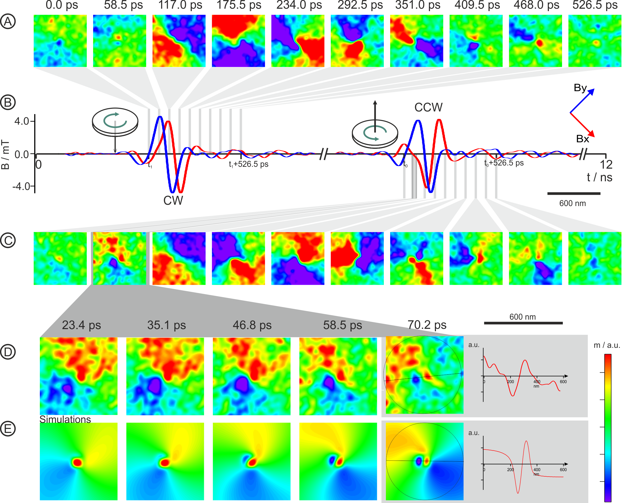
We explored the switching behavior of the vortex core by applying short magnetic field bursts, each with a one-period duration and at an excitation frequency of as sketched in Fig. 1, row B. For selective unidirectional switching of the vortex core polarity from down to up a burst with a CW sense of rotation has to be applied, followed by a burst with CCW sense of rotation which switches the vortex core polarity from up to down again. In that way time-resolved stroboscopic imaging was done in time steps as low as . Fig. 1 (A) shows selected time frames in intervals of displaying the out-of-plane magnetization of the spin waves during the CW excitation. The resulting vortex core up is again reversed, now by applying a magnetic field burst with CCW sense of rotation and the corresponding snapshots are shown in row C of Fig. 1.
The clear contrast in all stroboscopic images shown in Fig. 1 proves that for the parameter set used in our experiment (i.e., one-period burst at with an excitation field amplitude of ) an unidirectional (selective) switching is achieved, to vortex core up by a CW and to vortex core down by a CCW burst excitation - as otherwise the contrast of the vortex core polarity between each burst would be lost as a superposition of both states would occur. Later in this paper it will be shown, that this experimental finding is also in good agreement with micromagnetic simulations predicting unidirectional switching for the chosen excitation parameters (cf. Fig. 3, B left).
Experimental details on the developments of vortex magnetization of the vortex structure with vortex core up in the time region between and after CCW excitation has started are shown in Fig. 1 D which can be compared with corresponding micromagnetic simulations in Fig. 1 E. Magnetization profiles taken from the last time frames, after start of excitation, are printed in the last grey-shaded columns for both, the experimental and the simulated data. Both profiles are very similar and show, from left to right: (i) the magnetization of the positive part of the spin wave, (ii) the negative magnetization of the dip (i.e., the first stage of the developing vortex-antivortex pair which causes the reversal of the vortex core Kammerer2011 ), (iii) the positive magnetization of the original vortex core, and (iv) the magnetization of the negative part of the spin wave. It should be noted that this configuration is found for vortex core switching by CCW (CW) rotating azimuthal spin waves and vortex core up (down), whereas for the two other configurations (i.e, CW for vortex core up and CCW for vortex core down) a different, more simple configuration is observed. This asymmetry was already observed by simulations in (Kammerer2011 , Fig. 4) and is caused by the gyrotropic field (Kammerer2011 , Fig. 5). More experimental evidence on this phenomenon will be given in the next paragraph.
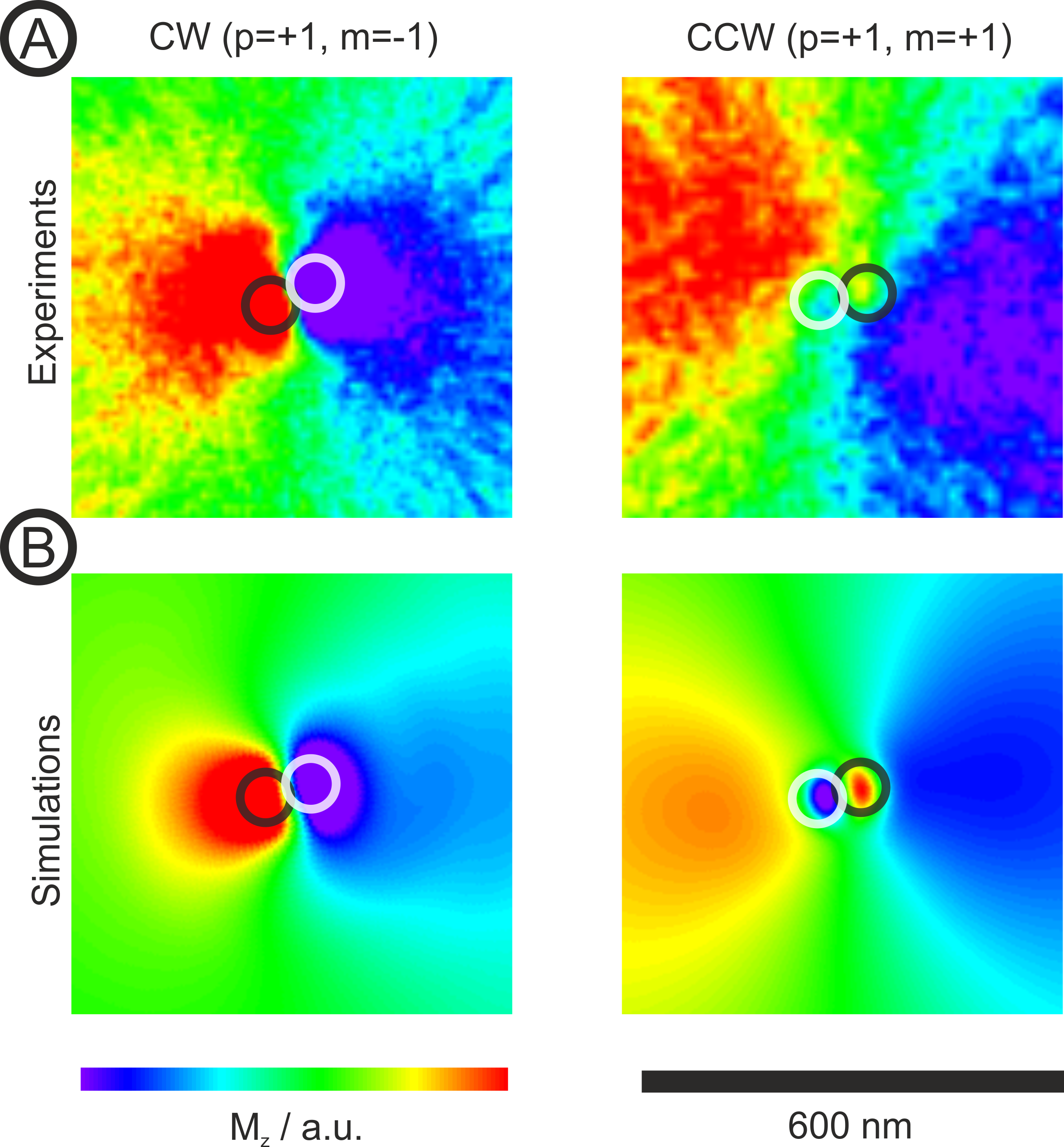
In order to study in more detail the asymmetry in switching the vortex core by azimuthal spin waves of opposite sense of rotation we excited the system by continuously rotating fields with a frequency of for the CW rotating spin wave mode () and for the CCW rotating mode (). The excitation amplitudes, for CW excitation and for CCW excitation, have been chosen just below the critical experimental value for core reversal at these specific frequencies Kammerer2011 . In contrast to the previous experiment (Fig. 1) where the magnetization configuration to be investigated could be observed only in a very short time frame before vortex core reversal, the continuous excitation just below the switching threshold level allows us to improve statistical accuracy significantly by measuring this magnetization configuration in a stationary state over a much longer time. For both, CW and CCW excitation, snapshots of the rotating magnetization have been taken at different phases of the rotation. These snapshots have been corrected in their rotation phase before averaging. The results are plotted in Fig. 2 A (left CW (), right CCW ()) and compared with the corresponding micromagnetic simulations, folded with the experimental resolutions (Fig. 2 B). In the case of CW excitation (left column), both, experiment and simulation reveal, that the vortex core (black circle) as well as the negatively polarized dip (white circle) is hidden behind the dipolar spin wave structure due to the limited lateral resolution. However, for CCW excitation, the vortex core (black circle) and the dip (white circle) exhibit a clear contrast due to their opposite polarization with respect to the spin wave profile. This agrees well with the snapshots and profiles in Fig. 1 (row C for experiments, row D for simulations). This asymmetry, which has already been described by simulations before (Kammerer2011 ; Guslienko2010 ), could now be imaged for the first time by an experiment. It is this asymmetry which causes the differences in the phase diagrams (Fig. 3 and 5) for CW or CCW rotating spin waves and therefore allows unidirectional vortex core switching with very short broad-band bursts as described in the following paragraph.
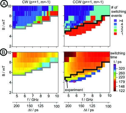
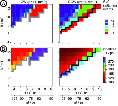
We have performed micromagnetic simulations for a Permalloy disc according to the measured sample size (diameter: , thickness: ) in order to explore vortex core switching for a single-period excitation as a function of excitation frequency and field amplitude. The initial state of the vortex core was up () in each of the simulations. The resulting phase diagrams are shown in Fig. 3. The left column denotes CW, the right column CCW excitation. (For starting with vortex core down () just interchange CW and CCW.) In the upper row (A) the number of switches during and after one burst is given as a function of excitation frequency and amplitude111Please note, that because of the high-frequency bandwidth of an excitation with one period only, narrow resonance frequencies are no longer observed, which are present for a -period excitation (Kammerer2011 , Fig. 2).
For reliable technological applications only the areas of single vortex core switching are relevant, which are marked red. Unidirectional switching is achieved at those frequencies and amplitudes, where the vortex core can be reversed with one sense of rotation only. Both conditions, unidirectional as well as single vortex core switching, are fulfilled for CCW excitation (cf. the upper right phase diagram in Fig. 3) in a wide area below the black line. Thus excitation frequencies from to and excitation amplitudes between and (depending on the excitation frequency) can be applied for unidirectional and single vortex core reversal with one period of the excitation frequency.
The next important information, which is derived from our simulations are the switching times which are shown in Fig. 3 B. In the area of unidirectional and single vortex core reversal, switching times as low as are obtained. In our experiment shown in Fig. 1 we obtained unidirectional vortex core reversal by a one-period excitation at (corresponding to an excitation time of ) at an amplitude of . At the corresponding point in the phase diagram of our simulations (marked ’experiment’ in Fig. 3, B right) a small window for unidirectional, single vortex core reversal around is found, which is in sufficient agreement with our experiment. According to the simulations, the switching time would be around , which corresponds to the sixth frame in Fig. 1 A and 1 C. Unfortunately, the ongoing rotation of the spin waves prevents us to derive a precise vortex core reversal time from the experimental data.
An important finding is, that the time needed for vortex core reversal exceeds the excitation time. In other words, a delay has been discovered between the end of excitation and the actual vortex core reversal event. To give an example: One period at corresponds to a excitation time, but at excitation amplitude vortex core reversal takes longer than (marked blue in Fig. 3, lower right diagram). Also in some other areas the switching time exceeds the excitation times by up to several . Two more examples which are marked at by the red circles in the right diagram of Fig. 3 B will be treated in more detail in Fig. 4 A and B.
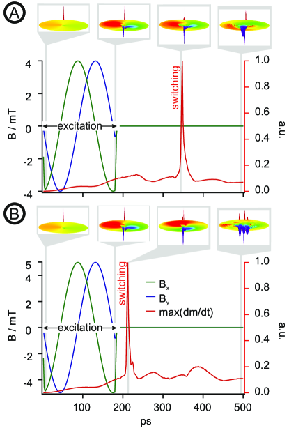
The delayed vortex core reversal is further investigated by more detailed analysis of micromagnetic simulations shown in Fig. 4. The same vortex structure as treated before was excited by a rotatiting one-period field at , but at two different amplitudes, 4 mT in the upper (A) and in the lower (B) image. The green and blue curve denotes the excitation fields in x and y direction (left scale), the red curve, corresponding to the left scale, shows the maximum temporal derivative of the magnetization. It was found, that the latter is a perfect indicator for vortex core reversal as it exhibits a sharp peak exactly when the original vortex core is annihilated.
At the same excitation time of the vortex core reversal time significantly decreased from (Fig. 4 A) to (Fig. 4 B) when the excitation amplitude is increased from to . However, a further increase of the amplitude results in multiple switching, where selectivity cannot be assured anymore. Following the phase diagram (Fig. 3 B, right plot), the single switching time for this sample geometry at a one-period excitation is limited to about at all excitation frequencies simulated ( to ).
In a next step we have investigated by micromagnetic simulations if the above limit in vortex core reversal time might be overcome by a shorter excitation time. For that purpose we excited the same sample with a reduced excitation time of half a period (c.f. Fig. 5). Comparison with a one-period excitation (Fig. 3) shows that also for half a periode excitation single switching can only be achieved with CCW excitation. compared to the one-period excitation, a higher switching threshold is observed in Fig. 5 A, increased by about a factor of since an approximately constant energy for switching is assumed which scales (in a linear approximation) with . The most important finding is that for half a period excitation the switching time for single switching is again found to be in the order of . Thus the limitation of the vortex core switching time of about according to Figs. 3 B and Fig. 4 B can not be overcome by the shorter excitation time.
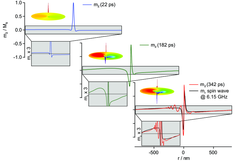
We would like to suggest an explanation for the limitation of the vortex core switching time discovered in our simulations. This explanation is based on a finite time for the energy transport (with spin wave velocities) from the outer area of the sample to a location near to the vortex core. Roughly speaking, the radially homogeneous excited spin wave amplitudes are concentrated in the center due to the concentric shape of the disc geometry. This is supported by additional micromagnetic simulations on the development of the normalized magnetization in z direction as a function of time as sketched in Fig. 6. The excitation parameters are the same as for Fig. 4 A (excitation amplitude: ). At three distinct time steps (please compare with the time scale in Fig. 4 A) one dimensional profiles are plotted of the magnetization at the symmetry axis of the spin wave. In the left plots in Fig. 6 the blue line denotes the radially homogeneous out-of-plane magnetization attributed to a precessional motion at the beginning of the excitation ( after the excitation has started) The inlay shows the same magnetization, by with a field scale enhanced by a factor of three. In the mid plots of Fig. 6, later and at the end of the excitation time of , the magnetization amplitude is already more concentrated to the middle of the sample as shown by the green profile. And finally in the right plots at , the concentration of the magnetization near the vortex core (red line) is high enough to form the vortex-antivortex-pair causing the vortex core reversal after excitation has ended. For comparison, the black line denotes the magnetization of the CCW rotating spin wave mode (, ) with an eigenfrequency of about . Acording to a rough estimation, the velocity of the energy transport to the center is approximately in the order of and thus matches with the typical velocities of magnetostatic spin waves.
Our simulations show that transport of the global energy towards the center of the vortex structure has to be considered for vortex core switching. In our sample ( in diameter, thick) the energy transport limits the switching time for singular vortex core reversal to about , even for shorter excitation bursts. However, as energy transport time (for a rough estimation) is in first order proportional to the sample size, our model implies that much shorter vortex core reversal times can be obtained at smaller samples.
To conclude, we have experimentally imaged spin wave mediated unidirectional vortex core reversal by time-resolved X-ray microscopy. The vortex core in a Permalloy disc, in diameter and thick, could be switched experimentally by a one-period () rotating ac magnetic field burst at . Unidirectional switching to up or down could be achieved by adjusting the sense of rotation of the ac field burst, in good agreement with the phase diagrams obtained by micromagnetic simulations. Simulations also show that this unidirectional (selective) vortex core reversal is possible due to significant differences for CW or CCW rotating azimuthal spin waves, based on the interaction of the gyrofield Thiele1973 ; Guslienko2008100 with the spin wave Kammerer2011 . These differences in vortex magnetization dynamics during excitation of CW or CCW rotation spin waves could now be imaged in an experiments by time-resolved scanning transmission X-ray microscopy.
Significant delays between the end of the excitation and vortex core reversal time of up to several have been found by micromagnetic simulations, depending on excitation frequency and amplitudes. This delay time can be reduced by increasing the excitation amplitude which is, on the other hand, limited due to multiple switching. As a consequence a lower limit for unidirectional vortex core reversal is observed (about for a sample geometry of in diameter and a thickness of ). This phenomenon is explained by the time needed for the energy transport of the global excitation towards the center.
Acknowledgements.
We would like to thank Manfred Fähnle, Eberhard Göring and Dieter Carstanjen, MPI Stuttgart for fruitful discussions.References
- (1) Huber, D., Journal of Applied Physics 53 (1982) 1899.
- (2) Shinjo, T., Okuno, T., Hassdorf, R., Shigeto, K., and Ono, T., Science 289 (2000) 930.
- (3) Wachowiak, A. et al., Science 298 (2002) 577.
- (4) Van Waeyenberge, B. et al., Nature 444 (2006) 461.
- (5) Curcic, M. et al., Physical Review Letters 101 (2008) 197204.
- (6) Curcic, M. et al., Physica Status Solidi. B, Basic Research 248 (2011) 2317.
- (7) Zagorodny, J., Gaididei, Y., Mertens, F., and Bishop, A., The European Physical Journal. B 31 (2003) 471.
- (8) Lee, K. and Kim, S., Physical Review B, Condensed Matter and Materials Physics 78 (2008) 014405.
- (9) Kravchuk, V., Sheka, D., Gaididei, Y., and Mertens, F., Journal of Applied Physics 102 (2007) 043908.
- (10) Kim, S., Lee, K., Yu, Y., and Choi, Y., Applied Physics Letters 92 (2008) 022509.
- (11) Kamionka, T., Martens, M., Chou, K., Curcic, M., and Drews, A., Physical Review Letters 105 (2010).
- (12) Bohlens, S. et al., Applied Physics Letters 93 (2008) 142508.
- (13) Pigeau, B. et al., Applied Physics Letters 96 (2010) 132506.
- (14) Park, J., Eames, P., Engebretson, D., Berezovsky, J., and Crowell, P., Physical Review B, Condensed Matter and Materials Physics 67 (2003) 020403.
- (15) Buess, M. et al., Physical Review Letters 93 (2004) 077207.
- (16) Buess, M. et al., Physical Review B, Condensed matter 71 (2005) 104415.
- (17) Buess, M., Haug, T., Scheinfein, M. R., and Back, C. H., Physical Review Letters 94 (2005) 127205.
- (18) Guslienko, K. Y., Slavin, A. N., Tiberkevich, V., and Kim, S.-K., Physical Review Letters 101 (2008) 247203.
- (19) Zhu, X., Liu, Z., Metlushko, V., Grutter, P., and Freeman, M., Physical Review B, Condensed Matter and Materials Physics 71 (2005) 180408.
- (20) Park, J. and Crowell, P., Physical Review Letters 95 (2005) 167201.
- (21) Neudecker, I. et al., Physical Review B 73 (2006) 134426.
- (22) Ivanov, B. and Zaspel, C., Physical Review Letters 94 (2005).
- (23) Zaspel, C., Ivanov, B., Park, J., and Crowell, P., Physical Review. B, Condensed Matter and Materials Physics 72 (2005).
- (24) Hoffmann, F. et al., Physical Review B, Condensed Matter and Materials Physics 76 (2007) 014416.
- (25) Guslienko, K., Aranda, G., and Gonzalez, J., Physical Review B, Condensed Matter and Materials Physics 81 (2010) 014414.
- (26) Gaididei, Y., Kamppeter, T., Mertens, F., and Bishop, A., Physical Review. B, Condensed Matter and Materials Physics 59 (1999) 7010.
- (27) Gaididei, Y., Kamppeter, T., Mertens, F., and Bishop, A., Physical Review. B, Condensed Matter and Materials Physics 61 (2000) 9449.
- (28) Kovalev, A. and Prilepsky, J., Low Temperature Physics 28 (2002) 921.
- (29) Kammerer, M. et al., Nature Communications 2 (2011).
- (30) Thiele, A. A., Physical Review Letters 30 (1973) 230.
- (31) Follath, R., Schmidt, J. S., Weigand, M., and Fauth, K., volume 1234 of AIP Conference Proceedings, American Institute of Physics, New York, 2010.
- (32) Jaeschke, E., BESSY-II, A State-of-the-Art Synchrotron Light-Source for Berlin-Adlershof, in EPAC 1992 - Third European Particle Accelerator Conference, VOL 1, pages 43–46, Editions Frontiers, Dreux, 1992.
- (33) Guslienko, K., Lee, K., and Kim, S., Physical Review Letters 100 (2008) 027203.