Spectral transformations in the regime of pulse self-trapping in a nonlinear photonic crystal
Abstract
We consider interaction of a femtosecond light pulse with a one-dimensional photonic crystal with relaxing cubic nonlinearity in the regime of self-trapping. By use of numerical simulations, it is shown that, under certain conditions, the spectra of reflected and transmitted light possess the properties of narrow-band (quasi-monochromatic) or wide-band (continuum-like) radiation. It is remarkable that these spectral features appear due to a significant frequency shift and occur inside a photonic band gap of the structure under investigation.
pacs:
42.65.Re, 42.65.Jx, 42.65.Ky, 42.65.HwI Introduction
The need for taking into account the noninstantaneousness of nonlinear response of a medium was realized soon after the rise of nonlinear optics. From the end of the 1960s specialists studied the influence of nonlinearity relaxation in the framework of the Debye model on such effects as laser beam self-focusing Fleck ; Hanson and parametric amplification Trillo . Among recent studies, attention has been attracted to modulational instability effects in media with noninstantaneous nonlinearity Shih ; Velchev ; Zhang , resulting in generation of pulse trains SotoCrespo and solitons Cambournac , instability of speckle patterns Skipetrov , and reshaping of solitary pulses Liu .
However, the theoretical nonlinear optics of photonic band gap materials usually deals with instantaneous processes of nonlinearity. Many results may be found in reviews and monographs (see, for example, Refs. Sakoda ; Gaponenko ; Bert ; Notomi ). We should also note some effects connected with ultrashort pulse interaction with nonlinear photonic crystals, such as pulse compression and temporal soliton formation Eggl ; Zhelt , subdiffractive propagation Stal ; Loiko , and pulse localization on a defect Good ; Mak1 ; Mak2 .
In this paper we consider spectral transformations of femtosecond pulses interacting with a one-dimensional photonic crystal with relaxing cubic nonlinearity. As was shown in our previous publication Novit , light self-trapping occurs in such a nonlinear structure due to formation of a nonlinear dynamical cavity (or trap) inside it. The present paper is a logical continuation of that paper. The importance of spectral investigation is connected with the possibility of spectral broadening, which in some extremal cases can result in supercontinuum generation. This phenomenon can be observed, for example, in photonic crystal fibers Dudley or in filamentation processes in bulk materials Couairon . Spectral broadening is one of the main points of our research.
The paper is logically divided into several sections. In Sec. II we give the problem formulation and consider some additional details of the self-trapping effect important for the present paper. Section III is devoted to the spectral features connected with the nonlinear interaction of a pulse with a photonic crystal in the regime of self-trapping. Finally, Sec. IV contains a short conclusion.
II Self-trapping effect
Propagation of an ultrashort pulse in a one-dimensional nonlinear photonic crystal [a structure of type] is described by the Maxwell wave equation
| (1) |
with the dependence of refractive index on light intensity as follows,
| (2) |
Here is the electric field strength, is the linear part of the refractive index varying along the axis, and is the nonlinear part of the refractive index, which is governed by the Debye model of relaxing nonlinearity Akhm
| (3) |
where is the Kerr nonlinear coefficient and is the relaxation time, which is assumed to be of the order of several femtoseconds (fast electronic cubic nonlinearity). Further we consider femtosecond light pulses with the amplitude of Gaussian shape , where is the pulse duration. To analyze the interaction of such a pulse with a nonlinear photonic crystal, we use the finite-difference time-domain method of numerical simulations which was described in detail in Ref. Novit . The spectra of pulses (incident, reflected, transmitted) in this paper are calculated as the absolute values of the Fourier transform of the corresponding field profiles. The spectra are normalized to the peak value of the incident pulse spectrum which is recognized as unity.
The parameters used in our calculations are as follows: the linear parts of the refractive indices of the layers and of the photonic crystal and , respectively; their thicknesses and m; the number of layers ; the pulse duration fs; the central wavelength of the initial pulse spectrum is m if not stated otherwise. The nonlinear coefficient of the material is defined through the nonlinear term of the refractive index, so that ; this means that the pulse amplitude is normalized by the value . The relaxation time of the nonlinearity of both layers is fs.
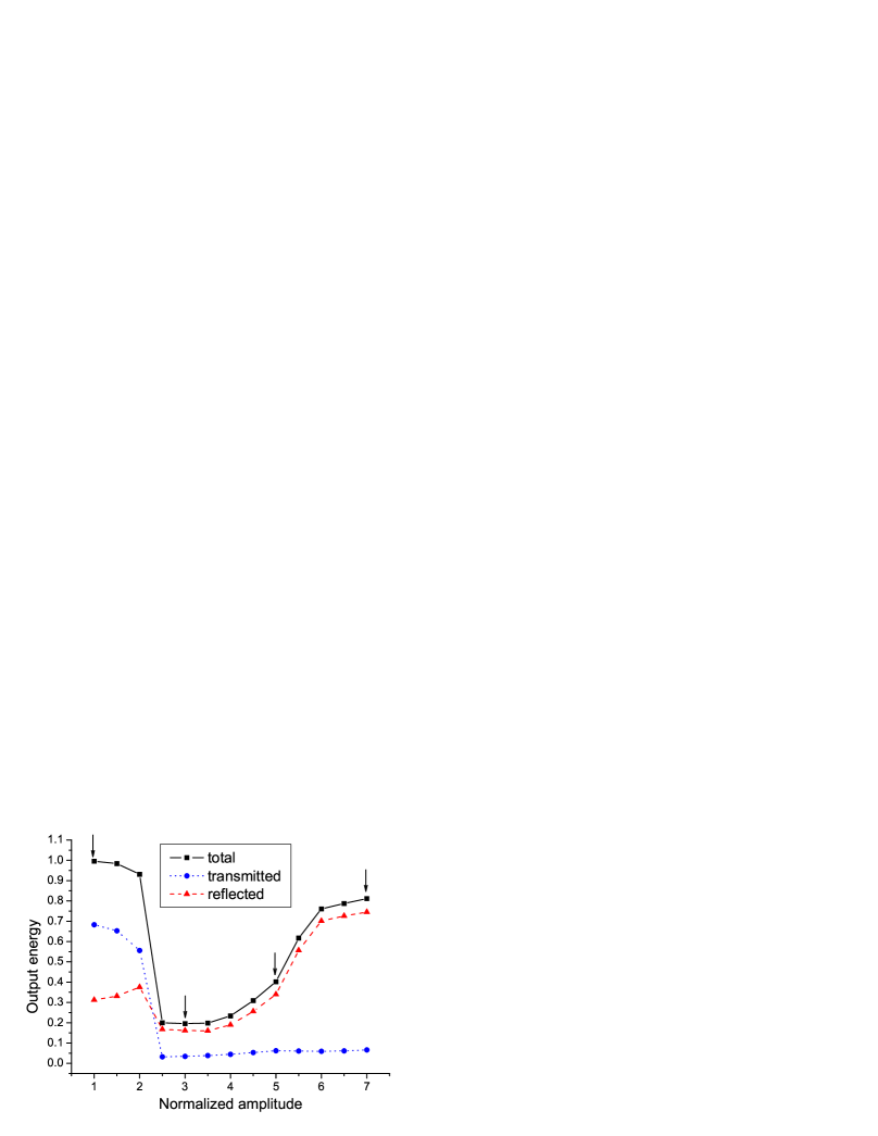
As it was predicted in our previous work Novit , the interaction of the pulse (whose duration is comparable to the relaxation time) with a nonlinear photonic crystal results in the effect of pulse self-trapping. This situation when the energy of radiation leaving the structure is only a small fraction of the incident pulse energy is shown in Fig. 1. It is seen that, for large enough intensity of the pulse, the output energy demonstrates a profound decrease corresponding to the self-trapping of the pulse inside the photonic crystal. The output energy is calculated by intensity integration over time at the input and output points of the structure; thus we obtain the energies of the reflected and transmitted light, and the total output energy is their sum. As the amplitude of the incident pulse increases further, light is trapped closer and closer to the input face of the crystal so that the reflected radiation energy gets larger and larger. Finally, the trapping occurs near the very input, so that most of the light is immediately reflected. The range of pulse durations and relaxation times for the self-trapping effect to be observed in our structure was studied in Ref. Novit as well: varies from a fraction of a femtosecond to about fs, and from about fs to about fs.

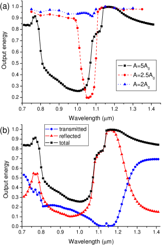
For better understanding of this effect, let us consider its frequency dependence. In Fig. 2 we see the reflectivity and group velocity dispersion (GVD) of the photonic crystal considered as functions of the light wavelength. It is well known that the GVD parameter is decisive in observation of pulse compression Akhm ; Zhelt . Indeed, if the nonlinearity coefficient is positive (this is the case in our consideration), then one needs to have a medium with negative GVD. Since the self-trapping effect is characteristic for the regime of pulse compression Novit , we can expect that the pulse will be trapped inside the photonic crystal if the pulse spectrum lies in the negative dispersion domain. This expectation is justified in Fig. 3 where the output energy dependence on the central wavelength of the pulse spectrum is represented. The dip in this dependence is unambiguously correlated with the negative-GVD region in Fig. 2(b). Moreover, the appearance of a minimum in the output energy implies that there are some competitive processes which come in contact and determine the result of the pulse-crystal interaction. It seems natural to suggest that these processes are dispersion spreading and nonlinear light-matter interaction as in the case of usual pulse compression.
Figure 3(a) also shows that, for larger values of the pulse amplitude, the optimal value of the central wavelength is situated further from the band gap (compare the curves at and ). At the same time, the dip for is deeper, which is in accordance with the assumption about optimal (or close to optimal) trapping in this case (see Fig. 1). Note that for there is no self-trapping behavior but, nevertheless, there is a very shallow dip even closer to the forbidden gap than at .
III Spectral features of light in the self-trapping regime

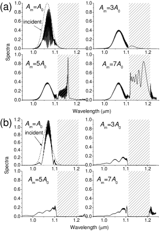
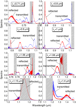
The change in shape of the reflected intensity connected with the dynamical trap formation can be traced in Fig. 4, where we plotted the results for different values of incident pulse amplitude corresponding to the cases marked by the arrows in Fig. 1. Most of all, we are interested in Figs. 4(c) and 4(d), which show some remarkable features to be discussed in detail. In contrast to the usual peaks of reflected light in Figs. 4(a) and 4(b), corresponding to the cases of zero trapping and maximal trapping, respectively, Fig. 4(c) was calculated for a point on the upward slope of the reflected energy curve (the amplitude is ). This means that self-trapping still exists but some part of the radiation leaves the nonlinear trap inside the photonic crystal. As one can see in Fig. 4(c), this leaving radiation represents almost stationary radiation for quite a long time. As a result, we can expect that the spectrum of reflected light has to possess a pronounced narrow peak corresponding to this quasi-monochromatic radiation. This expectation is entirely justified, as spectral plots demonstrate in Fig. 5(a). It is seen that, for , the spectrum of reflected light really has a sharp peak, while in the cases and the spectra approximately correspond to the spectrum of the incident Gaussian pulse. Moreover, the position of the spectral peak also provokes our interest, since it is situated deep inside the photonic band gap of the structure.
If we take a pulse with greater amplitude (), then, as mentioned above, the reflected light appears immediately with a wide and seemingly unstructured envelope [Fig. 4(d)]. It turns out that its spectrum in this case completely covers the band gap in continuum-like fashion [see Fig. 5(a)]. Note that the spectra of transmitted radiation do not intrude into the forbidden gap, as is witnessed by Fig. 5(b). In general, spectral broadening can be linked with self-phase-modulation resulting in the generation of new frequencies in the pulse spectrum due to the temporal variation of the refractive index Couairon . However, the fact that the sharp edges of the spectrum include just the entire band gap seems to be unexpected. In fact, we have a situation when light converts under nonlinear interaction in such a way that the spectrum is more and more pulled into the forbidden gap. On the other hand, we should keep in mind that self-trapping is connected with a local change of reflective properties of the photonic crystal Novit .
Thus, if we are on the upward slope of Fig. 1, we can obtain narrow-band radiation in reflection. In other words, this corresponds to stronger coupling between the pulse and the nonlinear structure than in the case of the optimal self-trapping effect due to the greater value of the incident intensity. One might suggest that something similar should be observed in the opposite situation when the light-medium interaction gets weaker, i.e. in the region of the very abrupt downward slope in Fig. 1. Obviously, the narrow-band spectrum is expected to be obtained in transmitted (not reflected) radiation in this case. In order to prove this statement, we use another method to make the coupling between the pulse and the nonlinear photonic crystal weaker. We take materials with smaller nonlinearity, rather than decreasing the intensity of the pulse. In Fig. 6 the results are shown for the -structure with linear layers, while the parameters of the layers remain unchanged. It is seen that the structure of the transmitted radiation is similar to that of Fig. 4(c). As a result, in the spectrum of transmitted light a pronounced quasi-monochromatic peak occurs [Fig. 6(b)]. This peak, however, is situated near the very edge of the band gap of the linear photonic crystal. Obviously, low-intensity quasi-monochromatic radiation seen in Fig. 6(a) cannot significantly change the refractive properties of the structure through which it is to be transmitted. Therefore, there is only a slight shift of the forbidden gap, which can be referred to as a self-induced transparency effect in the nonlinear photonic crystal.
Let us return to Fig. 3 and consider spectral transformations for incident pulses with different central wavelengths . The dip corresponding to the self-trapping phenomenon is situated between two band gaps plotted in Fig. 2 (we call it the inter-gap region). Changing in this region, one can obtain all the variants of spectral peculiarities discussed above and even more as can be seen in Fig. 7. Further, we list the main features seen in this figure:
(i) When the spectrum of the incident pulse is out of the inter-gap region ( m, which is the region of negative GVD; see Fig. 2), the spectrum of reflected radiation has a sharp peak near the very low-frequency (on the dip side) edge of a narrow band gap.
(ii) If the spectrum is in the positive-GVD domain ( m), the peak for reflected radiation still occurs, but there also appears a peak in the transmitted light spectrum near the edge of the wider (long-wave) band gap. Self-induced transparency is also observed due to the shift of the forbidden gap. Obviously, this situation corresponds to the weak light-matter coupling regime discussed previously in connection with Fig. 6.
(iii) As we move further inside the negative-GVD region (the region of the self-trapping dip, and m), the peaks near both the wide and narrow gaps diminish and become less and less pronounced (the peak for transmitted light moves away from the edge of the gap).
(iv) At m we see a narrow quasi-monochromatic peak actually inside the forbidden gap (compare with Fig. 5, ). Note that the reflected radiation also appears inside the narrow (short-wave) band gap.
(v) At m the reflected light spectrum in the band gap widens and takes a continuum-like shape with characteristic oscillatory fine structure (compare with Fig. 5 at ).
(vi) If the initial spectrum is almost entirely inside the band gap ( m), then we have the usual reflection without any evidence of nonlinear interaction.
(vii) At m we are also outside the dip and inside the positive-GVD region. The spectra of both reflected and transmitted light demonstrate a sharp break right on the edge (the side opposite to the dip) of the band gap. There is no any sign of self-induced transparency.
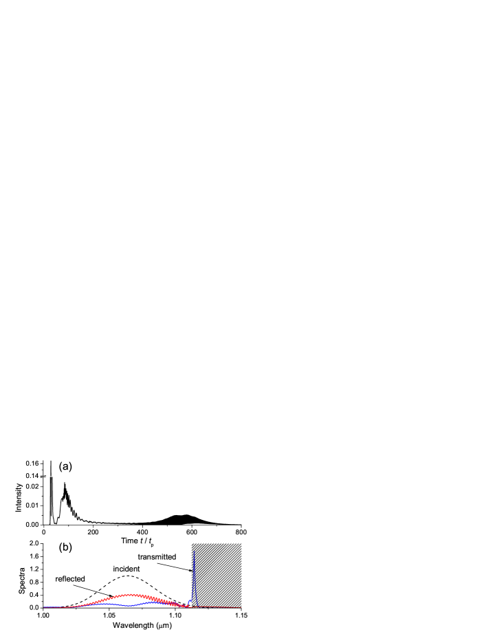
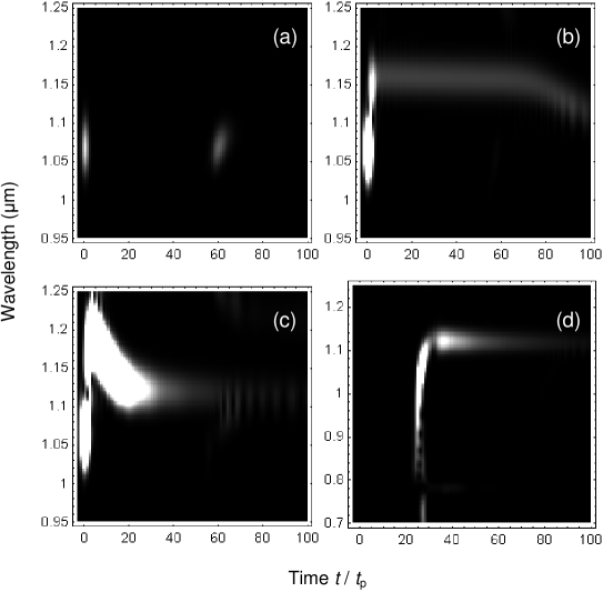
Finally, to make clear the connection between temporal curves and spectra, we turn to the spectrogram technique widely used in supercontinua investigation Dudley . The spectrogram is calculated as Dudley
| (4) |
where is the field under investigation (in our case, the reflected or transmitted field), is the gate function which is chosen to be a replica of the input pulse. The spectrogram allows an intuitive understanding of the correlation between temporal and spectral features of a given signal. In Fig. 8 such spectrograms are shown; Figs. 8(a)-8(c) corresponding to temporal and spectral curves of the reflected radiation depicted in Figs. 4 and 5(a), respectively. Figure 8(d) represents the spectrogram of transmitted radiation of the spectrum demonstrated in the upper right panel of Fig. 7 (the case of m).
The spectrogram of reflected light at the incident pulse amplitude [Fig. 8(a)] shows two intensity peaks seen in Fig. 4(a). These peaks are concentrated near the central wavelength m without any significant frequency shift. Such a shift is easily seen in Fig. 8(b) at , so that low-intensity quasi-monochromatic radiation occurs exactly inside the photonic band gap. It is also worth noting that at a frequency shift in the reverse direction (toward ) exists. This fact can be associated with the chaotic ending of quasi-monochromatic radiation seen in Fig. 4(c). For larger input intensity (), this reverse shift occurs earlier in time, but the spectrum covers a wider frequency range with approximately uniform intensity giving rise to continuum-like radiation inside the band gap. The last spectrogram [Fig. 8(d)] shows the transmitted quasi-monochromatic radiation with a large frequency shift from m to about m. It is easily seen that this shift happens very fast in time.
IV Conclusion
In conclusion, in this paper we have studied the spectral transformations of ultrashort (femtosecond) light pulses resulting from their interaction with a nonlinear photonic crystal in the regime of self-trapping. In our analysis we used only the processes of light self-action, so that the effect of generation of wide and narrow spectra cannot be connected by high harmonics and sum-frequency appearance. However, as our results demonstrate, these self-interaction processes are sufficient for impressive spectral transformations in nonlinear photonic crystals. These transformations concern both reflected and transmitted light spectra and depend on the regime of light-material interaction. In particular, if this interaction is strong (the pulse is trapped near the entrance of the photonic crystal), a narrow peak and continuum-like spectral features occur in reflected light. On the other hand, if the light-structure interaction is weak (the pulse is trapped near the exit of the photonic crystal), a narrow peak near the edge of the band gap appears in the transmitted light spectrum. Obviously, relaxing (noninstantaneous) behavior of the nonlinearity and periodic change of the linear refractive index (a photonic crystal per se) are the key conditions due to the necessity of self-trapping.
We should also say a few words about perspectives of this research. First, some improvements are possible in the realization and control of the self-trapping effect by adjustment of the photonic structure. In particular, a chirped photonic crystal with varying period can be employed to shift the trapping position inside the structure and, perhaps, to relax the requirements on the materials. However, this modification is still to be studied in detail. The second question is connected with the possibility of experimental realization of self-trapping and the corresponding spectral effects. Although the parameters used do not belong to some specific nonlinear medium, they seem to be quite realistic. The relaxation times (a few femtoseconds) are characteristic of media with a fast electronic mechanism of Kerr nonlinearity. However, such media possess relatively low nonlinear coefficients; therefore one has to use high-intensity pulses ( GW/cm2) and take into account the problem of the damage threshold, which is high enough in the case of femtosecond pulses. We believe that one can find some materials (for example, doped glasses Sutherland ) which satisfy all these conditions.
Acknowledgements.
The author thanks Dr. Andrey Novitsky for productive discussions and keen interest in this investigation. The work was supported by the Belarusian Foundation for Fundamental Research (Grant No. F11M-008).References
- (1) J.A. Fleck and P.L. Kelley, Appl. Phys. Lett. 15, 313 (1969).
- (2) E.G. Hanson, Y.R. Shen, and G.K.L. Wong, Appl. Phys. 14, 65 (1977).
- (3) S. Trillo, S. Wabnitz, G.I. Stegeman, and E.M. Wright, J. Opt. Soc. Am. B6, 889 (1989).
- (4) M.-F. Shih, C.-C. Jeng, F.-W. Sheu, and C.-Y. Lin, Phys. Rev. Lett. 88, 133902 (2002).
- (5) I. Velchev, R. Pattnaik, and J. Toulouse, Phys. Rev. Lett. 91, 093905 (2003).
- (6) L. Zhang et al., Opt. Commun. 283, 2251 (2010).
- (7) J.M. Soto-Crespo and E.W. Wright, Appl. Phys. Lett. 59, 2489 (1991).
- (8) C. Cambournac et al., J. Opt. Soc. Am. B19, 574 (2002).
- (9) S.E. Skipetrov, Opt. Lett. 28, 646 (2003).
- (10) X. Liu, J.W. Haus, and S.M. Shahriar, Opt. Commun. 281, 2907 (2008).
- (11) K. Sakoda, Optical Properties of Photonic Crystals, 2nd ed. (Springer, Berlin, 2005).
- (12) S.V. Gaponenko, Introduction to Nanophotonics (Cambridge University Press, New York, 2010).
- (13) M. Bertolotti, J. Opt. A 8, S9 (2006).
- (14) M. Notomi, Rep. Prog. Phys. 73, 096501 (2010).
- (15) B.J. Eggleton, R.E. Slusher, C.M. de Sterke, P.A. Krug, and J.E. Sipe, Phys. Rev. Lett. 76, 1627 (1996).
- (16) A.M. Zheltikov, N.I. Koroteev, S.A. Magnitskiy, and A.V. Tarasishin, Quantum Electron. 28, 861 (1998).
- (17) K. Staliunas, C. Serrat, R. Herrero, C. Cojocaru, and J. Trull, Phys. Rev. E74, 016605 (2006).
- (18) Yu. Loiko, R. Herrero, and K. Staliunas, J. Opt. Soc. Am. B24, 1639 (2007).
- (19) R.H. Goodman, R.E. Slusher, and M.I. Weinstein, J. Opt. Soc. Am. B19, 1635 (2002).
- (20) W.C.K. Mak, B.A. Malomed, and P.L.Chu, Phys. Rev. E67, 026608 (2003).
- (21) W.C.K. Mak, B.A. Malomed, and P.L.Chu, J. Opt. Soc. Am. B20, 725 (2003).
- (22) D.V. Novitsky, Phys. Rev. A81, 053814 (2010).
- (23) J.M. Dudley, G. Genty, and S. Coen, Rev. Mod. Phys. 78, 1135 (2006).
- (24) A. Couairon and A. Mysyrowicz, Phys. Rep. 441, 47 (2007).
- (25) S.A. Akhmanov, V.A. Vysloukh, and A.S. Chirkin, Optics of Femtosecond Laser Pulses (AIP Press, New York, 1992).
- (26) R.L. Sutherland, Handbook of Nonlinear Optics, 2nd ed. (Marcel Dekker, New York, 2003).