Luminosity Measurement Method for the LHC:
Event Selection and Absolute Luminosity Determination††thanks: This work was
supported in part by the programme of co-operation between the IN2P3 and
Polish Laboratories No. 05-117, Polonium Programme No. 17783NY and
Polish Grant No. 665/N-CERN-ATLAS/2010/0.
Abstract
Absolute normalisation of the LHC measurements with (1%) precision and their relative normalisation, for the data collected at variable centre-of-mass energies, or for variable beam particle species, with (0.1%) precision is crucial for the LHC experimental programme but presently beyond the reach for the general purpose LHC detectors. This paper is the third in the series of papers presenting the measurement method capable to achieve such a goal.
1 Introduction
The requirements for the luminosity measurement precision at the LHC are often misunderstood. According to the present paradigm [1], 2% precision is the benchmark and the ultimate target for the LHC experiments. Such a target may soon be reached by the method based on van der Meer scans for which has already been achieved [2].
The main argument underlying such a paradigm reflects the present precision of theoretical calculations of the cross sections for hard parton processes. These calculations are based on the perturbative, leading-twist QCD framework which allows only to approach the experimental precision target. Thus, as long as a significant reduction of uncertainties of both the matrix elements and the parton distribution functions (PDFs) is beyond the reach of the available calculation methods and DIS experiments, the impact of further reduction of the experimental luminosity error would hardly improve the present understanding of parton collisions.
In our view, there are at least four reasons to push the luminosity measurement precision frontier as much as possible.
-
1.
Precision observables, based on the data collected at variable c.m.-energies have been proposed for the precision measurement programme of the Standard Model parameters at the LHC [3], and for the experimental discrimination of the Higgs production processes against the SM ones [4]. These observables are specially designed to drastically reduce their sensitivities to the theoretical and modeling uncertainties limiting the overall measurement precision of the canonical ones. Their measurement precision is no longer limited by the theoretical and modeling uncertainties but by the precision of the relative luminosity measurements at each of the collider energy settings.
-
2.
The general purpose LHC experiments, ATLAS and CMS, and the specialised experiment, LHCb, measure the same parton cross sections in different regions of the phase-space. Relative normalisation of their results determine the ultimate LHC precision for those of the measurements which are based on a coherent analysis of their data. The best example here is the measurement of associated with concurrent unfolding of the valence and sea quarks PDFs.
-
3.
The LHC collides proton beams while the Tevatron collides proton and anti-proton beams. The and boson differential cross sections measured at these two colliders constrain the flavour dependent PDFs within the precision of the relative LHC and Tevatron luminosity measurements because the theoretical uncertainties on the hard partonic cross sections largely cancel in the cross section ratios.
-
4.
A fraction of the LHC running time is devoted to collisions of ions. The precision of the relative normalisation of the interaction observables with respect to the corresponding ion-ion ones is crucial for a broad spectrum of measurements ranging from the classical measurements of the shadowing effects to more sophisticated ones including the experimental studies of the propagation of W and Z bosons in the vacuum and in the hadronic matter [5].
For all the above and many other reasons any future improvement of the luminosity measurement precision will be directly reflected in the increased precision of the interpretation of the LHC measurements in terms of the Standard Model (SM) and Beyond the Standard Model (BSM) processes, in particular if specially designed precision observables are used.
The method of the luminosity measurement proposed in this series of papers attempts to push the precision frontier as much as possible at hadron colliders. Its ultimate goal is to reach the precision of (1%) for the absolute normalisation of the LHC measurements and of (0.1%) for the relative normalisation of the data recorded at variable centre-of-mass energies or different beam particle species (protons, ions). It is based on the detection of those of the electromagnetic collisions of the beam particles in which they can be treated as point-like leptons. For these collisions the corresponding cross sections can be calculated with a precision approaching the one achieved at lepton colliders. In this series of papers such collisions are tagged by the associated production of the unlike-charge electron-positron pairs.
In the initial paper [6] of this series we have selected the phase-space region where the lepton pair production cross section is theoretically controlled with precision better than 1%, is large enough to reach a comparable statistical accuracy of the absolute luminosity measurement on the day-by-day basis and, last but not the least, its measurement is independent of the beam emittance and of the Interaction Point (IP) optics. Collisions of the beam particles producing lepton pairs in this phase-space region cannot be triggered and selected by the present LHC detectors. A new detector must be incorporated within one of the existing general purpose LHC detectors to achieve this goal.
In our second paper [7] the performance requirements for a dedicated luminosity detector were discussed. In the present paper we discuss the luminosity measurement procedure based on the concrete luminosity detector model and on the present host detector performance parameters. We evaluate quantitatively the systematic precision of the proposed luminosity measurement method.
This paper is organised as follows. In Section 2 the model of the luminosity detector is introduced. Section 3 specifies the performance requirements for the host detector. The on-line selection procedures for the luminosity events are proposed in Section 4 and optimised in Section 5. Section 6 presents the rates of the signal and background events at the consecutive stages of the event selection process. The methods of monitoring of the instantaneous, relative luminosity are described in Section 7. Section 8 introduces the luminosity measurement methods for the low, medium and high luminosity running periods of the LHC machine. Merits of the dedicated runs are discussed in section 9. Section 10 introduces a novel and simple method of calculating the absolute cross sections for any sample of the user-selected events. Finally, Section 11 is devoted to the evaluation of the systematic uncertainties of the proposed luminosity measurement method.
2 Luminosity Detector Model
In the studies presented below the model of the luminosity detector is specified in terms of a minimal set of its required output signals. Its concrete hardware design is open and depends solely on the specific constraints imposed by the host detector construction and by the wishes of the host detector collaboration. The luminosity detector can be realised using one of the available particle tracking technologies and does not require dedicated R&D studies. The D0 fibre tracker [9] can serve as an example in most of its functional aspects with a notable exception of the radiation hardness issue which would need to be addressed anew in the LHC context.
The geometry of the proposed luminosity detector model was presented in [7]. The detector fiducial volume consists of two identical cylinders placed symmetrically with respect to the beam collision point. Each cylinder is concentric with the proton-proton collision axis defined in the following as the -axis of the coordinate system. The cylinders have the following dimensions: the inner radius of 48 cm, the outer one of 106 cm and the length of 54.3 cm. They occupy the regions between cm and cm and cm and cm. Each cylinder contains three layers (the planes) providing the measurements of the charged particles hits. These planes are positioned at the distances of , and cm from the interaction point. Each of the luminosity detector -planes is segmented into 3142 -sectors providing the azimuthal position of the hits111Adding the pseudorapidity segmented -planes (or equivalently -tilted planes) would certainly be useful, in particular for the periods of the highest LHC luminosities. Since, the main purpose of this paper is a proof of principle, these aspect will not be discussed further here. The presented luminosity detector model can be thus considered as the model of the base-line detector satisfying a minimal set of requirements.. Such a detector could occupy the space foreseen for the TRT C-wheels - a sub-component of the ATLAS detector which has not been built.
The basic role of the luminosity detector is to provide, for each charged particle , produced in collisions, the “track segment”, specified in terms of the three azimuthal hit positions, , where is the plane number and denotes the particle number. It is assumed that each reconstructed track segment has a “time-stamp”. The time-stamp assigns the track segment to the ns wide time slot synchronised with the machine clock222Note that this requirement may lead to adding, if necessary for a chosen technology, an extra, coarse -granularity timing plane in front of the three highly segmented hit planes.. Further timing requirements, discussed in detail in [7], such as adding a precise, sub-nanosecond relative timing for each of the -hits, for a better level 1 (LVL1) trigger resolution of the position of the origin of the track segments, are not required in the base-line detector model.
The time stamped track segments and their associated hits are the input data for the algorithmic procedures allowing to select, within the 2.5 LVL1 trigger latency of the host detector, the “luminosity measurement bunch crossings” and “monitoring bunch crossings”. The subsequent event selection algorithms are based solely on the host detector signals. The “Region of Interest” (ROI) [8] mechanism is used to correlate, within the level 2 (LVL2) trigger latency, the luminosity detector data with the relevant data coming from the host detector.
3 Host Detector Model
The ATLAS detector [8] was chosen in our studies as the host detector. The following data coming from this detector are used in the LVL2 and Event Filter (EF) trigger algorithms:
-
•
the parameters of the tracks selected using the ROI mechanism – available within the LVL2 0.01 s long trigger latency. We recall here that the luminosity detector angular acceptance is covered fully by the acceptance of the ATLAS silicon tracker [8],
-
•
the energies, the shape variables and timing of the electromagnetic/hadronic clusters in the LAr calorimeter in the ROI-restricted () regions – available within the LVL2 trigger latency,
-
•
the reconstructed hits in the LUCID detector [8] – available within the LVL2 trigger latency,
-
•
the reconstructed hits in the BCM (Beam Current Monitor)[8] – available within the 1 s long Event Filter (EF) trigger latency,
-
•
the precise parameters of the vertex-constrained tracks and the multiplicity of all the charged particles with GeV/c produced within the range of pseudorapidity – available within the EF trigger latency.
It is assumed further that the following host detector performance requirements will be fulfilled:
-
•
the pion/electron rejection factor of 10 at both the LVL2 and the EF trigger levels,
-
•
full identification of bunch crossings in which the charged particles are traversing the LUCID detector (),
-
•
full identification of bunch crossings in which the charged particles are traversing the BCM () detector.
In the studies presented below the host detector measurement and event selection biases are not taken into account. The LVL2 and the EF event selection efficiencies, the reconstruction and the electron/positron identification efficiencies, for the specified above values of the electron/pion rejection factors, are thus set to be equal 1. It is further assumed that the lepton pair momentum vectors are reconstructed with infinite precision.
Detailed studies based on realistic host detector performance simulations, indispensable if the proposed method is endorsed by the host detector collaboration, are both external to the scope of this paper and, more importantly, of secondary importance. The luminosity measurement method presented in this series of papers was designed such that all the host detector measurement biases, resolution functions and efficiencies can be determined directly using the data coming from the host detector recorded event samples.
The selection algorithms are discussed below for the two settings of the strength of a uniform solenoidal magnetic field: and T which are labeled respectively as and . These two magnetic field configurations correspond to the zero current and the nominal current of the ATLAS central tracker solenoid.
4 Event Selection Model
4.1 Level 1 Trigger
The luminosity detector trigger logic analyses the pattern of hits on a bunch-by-bunch basis. In the first step it selects only the “low multiplicity bunch crossing” candidates [7] i.e. the crossings with less than hits in both the and the sections of the luminosity detector333The parameter depends upon the processing power of FPGA-based electronics..
In the second step, for each low multiplicity bunch crossing, the track segments are formed and time-stamp validated. The time-stamp validation of the track segments consist of assigning each of them to one of the following two classes: the “in-time segments” and the “out-of-time segments”. These and the subsequent LVL1 selection steps are distinct for the and magnetic field configurations.
4.1.1 Case
In the case a track segment is formed by any combination of the hits, , and , in the three detector planes satisfying the following requirements:
AND
OR
|
OR
|
The parameter value is driven by the luminosity detector thickness expressed in units of the radiation length.
The in-time segments have the time stamps within the time window of width and an off-set of with respect to the bunch crossing time stamp. All the other track segments are assigned to the out-of-time class444For a detailed discussion of the timing of the luminosity detector signals see [7].. In the case the width of the time window reflects both the longitudinal LHC bunch size and the radial size of the luminosity detector.
A bunch crossing is selected by the luminosity detector LVL1 trigger as the “2+0” candidate if there are exactly two in-time track segments specified in terms of the hit triples: , , (, , ) in the left (right) detector part and no in-time track segments in the opposite right(left) one. The “coplanar pair” bunch crossing candidates are those of the “2+0” ones in which the hit positions in the first and in the third plane satisfy the following conditions:
The above conditions represent the algorithmic, LVL1 trigger implementation of the coplanar particle pair selection procedure for the magnetic field configuration discussed in [7].
A bunch crossing is selected as the “silent bunch crossing” candidate if there are no in-time track segments in both the left and right side of the luminosity detector.
4.1.2 Case
In the case a track segment is formed by any combination of the hits , , in the three detector planes which satisfy the requirements outlined below:
AND
OR
|
OR
|
The magnetic field strength dependent value drives the effective momentum cut-off of the charged particles reaching the luminosity detector. The in-time track segments have the time-stamps within the time window of width and the off-set of ns with respect to the bunch crossing time-stamp. The timing parameters are different for the and cases because for a given charged particle its track length measured from the interaction vertex to the entry point into the fiducial volume of the luminosity detector is different in these two cases.
For the equidistant spacing of the -planes the track segment finding and the time-stamp validation algorithms remain invariant with respect to the change of the magnetic field configuration - its influence is restricted only to the parameters of the algorithms.
As in the case, a bunch crossing is selected, by the luminosity detector LVL1 trigger, as the “2+0” candidate if there are exactly two in-time track segments in the left (right) detector part and no in-time track segments in the opposite one. However, in the case a supplementary condition is required to retain only the opposite charge particle tracks:
The “coplanar pair” bunch crossing candidates are those of the “2+0” ones in which the hits , satisfy the following conditions:
The above conditions define the LVL1 trigger algorithm for the coplanar particle pair selection procedure for the magnetic field configuration (see [7] for detailed discussion).
Similarly to the case, a bunch crossing is selected as the silent bunch crossing if there are no in-time track segments in both parts of the luminosity detector.
4.2 LVL1 Trigger Bits
It is assumed that the following LVL1 trigger bits are sent by the luminosity detector to the Central Trigger Processor (CTP) of the host detector:
-
•
the “coplanar pair candidate” (CPC) trigger bit,
-
•
the “2+0” (two plus zero - TPZ) trigger bit,
-
•
the “silent bunch crossing” (SBC) trigger bit,
-
•
the “low multiplicity bunch crossing” (LMBC) trigger bit.
They are assumed to be broadcasted on the bunch-by-bunch basis. For the CPC (TPZ)-trigger-selected bunch crossings the information on the -sector positions of the two in-time track segments is delivered the host detector Level 2 trigger algorithms using the ROI mechanism. The CPC trigger is not prescaled at the CTP level.
While the CPC-selected bunch-crossing data are used in the luminosity determination, the CTP-prescaled TPZ, SBC and LMBC ones, together with the CTP-selected random bunch crossings data, are used for a precision monitoring of the luminosity detector performance. In particular, in all the aspects which require correlating of the luminosity detector signals with the host detector ones on bunch-by-bunch basis.
4.3 Level 2 Trigger
The next step in the event selection chain is based entirely on the host detector LVL2 trigger algorithms. In the following we shall discuss only the LVL2 selection criteria for the LVL1-accepted coplanar pair candidate events, for which the CPC trigger bit was set to one555The LVL2 and EF processing of the monitoring events will be discussed later while addressing the precision of the proposed luminosity measurement method.. As before, the selection criteria are different for each of the two magnetic field configurations.
4.3.1 Case
In the first step of the LVL2 selection algorithm chain a search for a narrow energy cluster of the total energy above 1 GeV is performed. The search is confined to the electromagnetic calorimeter -sectors pointed out by the luminosity detector LVL1 ROI. If two electromagnetic clusters are found and if their timing, determined from the pulse-shapes in the channels belonging to clusters, is compatible with the track segment time-stamp the event is retained for the subsequent selection steps. The next step links the luminosity detector track segments to the Silicon Tracker (SCT) hits. If the linking is successful and if the corresponding SCT track segments cross each other in a space point within the proton bunch overlap IP region then the reduced acoplanarity is recalculated using the SCT hits. Events are retained for further processing if is fulfilled. The subsequent algorithm verifies if both clusters pass the electron selection criteria by analysing their lateral and longitudinal shape. Events passing all the above selection steps will be called in the following the LVL2 trigger “inclusive electron-positron pair” candidates. In the subsequent LVL2 step the LUCID detector signals are analysed and an event is selected as the LVL2 “exclusive electron-positron pair” candidate if there are no in-time particle hits in the LUCID tubes666The LUCID “particle hit” is expected to be set at a sufficiently high discriminator threshold to be as much as possible noise-free..
4.3.2 Case
The only difference in the selection steps of the LVL2 exclusive electron-positron pair candidates for the case is that the cluster energy cut is no longer imposed. This is because the equivalent cut, was already made by the LVL1 trigger.
4.4 Event Filter
The LVL2 selection of the exclusive electron-positron pair candidate events is subsequently sharpened at the Event Filter (EF) level. Similarly to the LVL1 and LVL2 cases the selection criteria for both configurations of the magnetic field slightly differ.
4.4.1 case
In the first step of the EF selection algorithm chain events with any reconstructed particle tracks within the tracker fiducial volume other than the tracks of the electron pair candidate are rejected. Subsequently, the reduced vertex acoplanarity is recalculated using the re-fitted vertex constrained values of the parameters of the lepton tracks and the cut is sharpened. Next, the EF electron selection algorithms exploiting full information coming from both the tracker and the LAr calorimeter are run and a further rejection of hadrons mimicking the electron signatures is performed. Finally, the event exclusivity requirement is sharpened by demanding no particle hits in the BCM in a tight time window.
4.4.2 Case
There are only two differences in the selection steps of the exclusive lepton pair candidates in the field configuration case. These are:
-
•
a replacement of the exclusivity criterion using the reconstructed track segments by the corresponding one based on the reconstructed tracks with the transverse momentum GeV/c,
-
•
a restriction of the transverse momentum of a pair to the region GeV/c.
5 Optimisation of the LVL1 Trigger
5.1 Algorithm parameters
The LVL1 trigger optimisation goal is to determine an optimal set of the algorithm parameters. These parameters, defined in Section 4.1.1 and 4.1.2, specify:
-
•
the definition of the track segments,
-
•
the classification of the track segments into the in-time and out-of-time classes,
-
•
the coplanarity of particle pairs (at the interaction vertex).
An optimal set of parameters maximises the rate of the exclusive coplanar pair candidate events while retaining the overall luminosity detector LVL1 trigger rate at kHz level. The latter restriction takes into account the present capacity of the ATLAS TDAQ system and assumes that at most of its throughput capacity can be attributed to the luminosity detector triggered events. For these events the event record length and the LVL2 and the EF filter processing times are significantly smaller than for any other physics triggers of the present host detector LVL1 trigger menu. Therefore, the strain on the LVL2 and EF throughputs is negligible.
The LVL1 trigger algorithm parameters were optimized by simulating the selection process for large samples of the bunch crossings containing the signal and the background events. The LVL1 trigger algorithms assigned the 0 or 1 values to the CPC, SBC and LMBC LVL1 trigger bits for every bunch crossing777The electron-positron pair signal events were generated with the LPAIR [10] generator. This generator was upgraded to suit our needs (see [6] for details). For the simulations of the minimum bias events the PYTHIA [11] event generator was used. As discussed in details in our earlier papers [6], [7], the studies were based on simplified methods of particle tracking in the detector magnetic field, parametrised simulation of their multiple scattering in the dead material, and on conservative estimation of the effects of the photon radiation by electrons..
The following sets of parameters maximises the signal to background ration while retaining the overall luminosity detector LVL1 trigger rate below 2 kHz level:
-
•
track segment definition:
-
•
selection of in-time track segments:
-
•
pair acoplanarity selection:
The corresponds to the effective low-momentum cut-off for particles producing a track segment in the luminosity detector of 1 GeV/c. The reflects the assumed thickness of the detector planes of 0.1 each. The increase of the width of the in-time window, for the case reflects the dispersion of the helix length of the charged particle trajectories between the interaction vertex and the first plane of the luminosity detector. The optimal selection region of coplanar pairs is illustrated in Fig. 1 for a chosen set of selection parameters.
Note, that for the configuration a sizable fraction of the electron-positron pair signal events is rejected by the track segment validation criteria. In these events at least one of particles has the momentum lower than 1 GeV/c.
The selection efficiency of the coplanar particle pairs is determined using the reduced acoplanarity, , variable which is defined as
with
where , are the azimuthal angles of the particles at the interaction vertex.
5.2 Algorithm efficiency
The efficiency of the LVL1 trigger algorithms of selecting the coplanar particle pairs using the above sets of parameters is illustrated in Fig. 2. In this figure the reduced acoplanarity distributions are plotted for the signal and background events, the two magnetic field configurations and for the initial and the CPC-trigger selected samples events. In the case the LVL1 algorithms rejects majority of the background events while retaining the signal events. In the case of the field configuration a sizable reduction of the electron-positron pair selection efficiency is not related to the luminosity detector performance. It is almost entirely driven by the constraint on the luminosity detector position within the host detector fiducial volume giving rise to a large probability of bremsstrahlung of the hard photon by the electron or positron on the path between the collision vertex and the luminosity detector entry point.
The efficiencies presented above correspond to the most pessimistic assumptions on the luminosity detector performance and on the dead material budget in front of the luminosity detector. Firstly, the base-line luminosity detector model was used. This model does not employ a precise relative timing in each of the three detector planes. Therefore, the event-by-event LVL1-trigger reconstruction of the position of the collision vertex, an option discussed in our previous paper [7], was not made. Such a function would significantly improve the sharpness of the LVL1 acoplanarity algorithm. Secondly, the studies were made for the 0.9 of dead material in front of the luminosity detector giving a rise to large multiple scattering effects. Thirdly, and most importantly, the hard photon radiation was assumed to take place at the collision vertex, inducing significant loss of efficiency for the case. Therefore, the results in this section represents the most conservative estimate of the electron-positron pair event selection efficiency.
6 Rates
In Figure 3 the integrated rates of the LVL1-accepted coplanar pair candidate events are plotted as a function of the upper limit on the pair for the two magnetic field configurations, for the signal and the background events. The distributions for the background events are shown at all the stages of the event selection procedure. This plot was made for the machine luminosity of cm-2 s-1 distributed uniformly over all the available bunch crossing slots.
This figure demonstrates that the proton-proton collisions producing coplanar electron-positron pairs can be efficiently selected from the background of minimum bias events. A reduction of the signal rate seen for the field configuration as compared to the configuration is driven mainly by radiation of hard photons by the electrons/positrons passing the host detector dead material. The signal to noise ratio is the largest for the smallest reduced acoplanarity cutoff. It underlines the need for a fine -segmentation of the luminosity detector.
In Figure 4 the ratio of the signal to the background rates at the EF selection stage is shown as a function of the machine luminosity for the three values of the upper limit of the reduced acoplanarity for the two settings of the detector magnetic field. These plots show that, already for the model of the base-line detector, the proposed event selection procedure assures a comfortable value of the signal to noise ratio over a large range of the machine luminosities. The drop of the signal to noise ratio for large luminosities is driven solely by a decreasing probability of the silent bunch crossing. For the case the signal to background ratio can be improved significantly by selecting events in a narrow bin of the reduced acoplanarity.
In Figure 5 the signal rates for events passing the EF selection stage are shown as a function of the machine luminosity for the three values of the reduced acoplanarity cut. The rates drop significantly below the initial level of 1 Hz level discussed in [6] but are sufficiently high to provide a statistically precise measurement of the luminosity.
For the luminosities below s-1cm-2 the rate of the signal events rises with increasing luminosity. At higher luminosities the apparent rate drop is a consequence increasing average number of collisions per bunch crossing. For s-1cm-2 a 1% statistical precision can be achieved over the integrated time intervals of about 30 hours for the configuration and about 400 hours for the configuration. These time intervals could be decreased significantly if the LVL1 track acoplanarity tagging were made in vicinity of the collision vertex - a solution which is presently out of reach for the existing trackers of the LHC detectors but can be reconsidered while upgrading the LHC detector’s trackers for the high luminosity phase of collider operation.
It is important to note that the direct extension of the proposed method beyond the luminosity value of s-1cm-2 requires at least one of the following three possible upgrades of the base-line luminosity detector:
-
•
adding a precise hit-timing measurement,
-
•
adding the z-planes to the luminosity detector and developing fast algorithms capable to determine the z-position of the track origins with a 1 mm precision within the LVL1 trigger latency,
-
•
adding the LVL1 trigger electron/pion rejection capacity functions.
If such upgrades are not made, the absolute luminosity can be measured in the low and medium luminosity periods and subsequently “transported” to the high luminosity periods. Foundation of such a procedure is precise monitoring of the relative instantaneous luminosity over the whole range of the LHC luminosities and in fine time intervals.
7 Monitoring of Instantaneous Luminosity
7.1 Goals
There are two basic reasons to measure the relative, instantaneous changes of the luminosity, , with the highest precision:
-
•
the method discussed here can reach the absolute luminosity precision target only for selected runs and selected bunch crossings and must be subsequently transported (extrapolated) to all the runs and bunch crossings,
-
•
the statistically significant samples of the electron-positron pair production events are collected over the time periods which are sizeably longer than the time scales of the changes in the detector recorded data quality (the electronic noise, the beam related noise, the event pile-up, the detector calibration and efficiencies, etc.) – the time evolution of the corresponding corrections must thus be weighed according to the instantaneous luminosity in the precision measurement procedures.
Precise measurement of the relative instantaneous luminosity in fine time intervals is bound to be based on the rate of strong rather than electromagnetic interactions of the beam particles. In the scheme proposed in this paper the on-line luminosity is determined by counting the luminosity detector in-time track segments produced in strong interactions of the colliding protons. It is determined using solely the luminosity detector data and its local data acquisition system. The on-line luminosity is determined in minute intervals. The corresponding final off-line luminosity is then recalculated using the data recorded by the host detector.
7.2 Counters
The following luminosity detector counters are proposed for a precision measurement of the instantaneous, relative on-line luminosities:
-
1.
Track-Global - representing the mean number of the in-time track segments per bunch crossing both in the left and in the right side of the luminosity detector,
-
2.
Track-Global-OR - representing the mean number of the in-time track segments per bunch crossing seen in both parts of the luminosity detector with the additional requirement that only those bunch crossings are considered for which there is at least one in-time track segment in either the left or in the right side of the luminosity detector,
-
3.
Track-Global-AND - representing the mean number of the in-time track segments per bunch crossing in both sides of the luminosity detector with the additional requirement that only those bunch crossing are considered for which there is at least one in-time track segment in each of the luminosity detector sides,
-
4.
Track-Event-OR - representing the fraction of bunch crossings with at least one in-time track segment either in the left or in the right half of the detector,
-
5.
Track-Event-AND - representing the fraction of bunch crossings with at least one in-time track segment in each of the detector halfs,
-
6.
Track-Left (Right) - representing the mean number of the in-time track segments per bunch crossing in the left (right) part of the luminosity detector,
-
7.
Track-Event-OR-Left(Right) - representing the fraction of bunch crossings with at least one in-time track segment in the left (right) side of the luminosity detector,
-
8.
Track-Sector( - representing the mean number of the in-time track segments per bunch crossing in the –th -sector of the left (right) side of the luminosity detector,
-
9.
Track-Sector-OR( - representing the fraction of bunch crossings with at least one in-time track segment in the –th -sector of the left (right) side of the luminosity detector,
-
10.
Track-Sector-Coinc( - representing the mean number of the in-time track segments per bunch crossing in the –th -sector of the left detector side and in the –th -sector of the right detector side,
-
11.
Track-Sector-Coinc-AND( - representing the fraction of bunch crossings with at least one in-time track segment both in the –th -sector of the left detector side and in the –th -sector of the right detector side,
-
12.
Track-SBC - representing the fraction of bunch crossings with no in-time track segments in each detector side.
Subdividing the sample of track segments into 36 -segment sub-samples allows to provide precise measurements over the whole range of the LHC luminosities ( cm-2s-1) independently of the number of pile-up collisions occurring within the same bunch crossing.
The counting is done separately for paired, unpaired (isolated and non-isolated) and empty (isolated and non-isolated) bunch crossings. The counters proposed above, together with the corresponding hit-based and out-of-time track segments based counters, provide the necessary input data to determine also the instantaneous luminosity of the LHC in the whole range of the average number of collisions per bunch crossing, and in the full range of the dispersion of the bunch-by-bunch luminosity. The track segment based counters, contrary to the LUCID or BCM detector ones [13], are insensitive to the beam induced background and afterglow effects obscuring the extrapolation of the van der Meer scan luminosity to arbitrary data collection periods. Moreover, they can be precisely controlled in the off-line analysis of the host detector tracks traversing the luminosity detector volume.
While the first five counters provide a fast diagnostic for the and dependent optimisation of the luminosity counting method, the following six counters are used directly by the instantaneous luminosity measurement algorithms. A detailed presentation of the counting algorithms is outside the scope of the present paper and will not be discussed here. The only aspect which may be elucidated is the extension of presently applied methods of the instantaneous luminosity measurement [13] to the full range of . As the value increases the inclusive track counters are replaced, at first by counting of tracks separately in each of the -sectors of both detector parts, and eventually, at the highest , by counting of the left-right -sector coincidences. For such a “step-by-step” procedure the unfolding of the number of interaction per bunch crossing is no longer necessary.
Since the value is determined locally by the luminosity detector algorithms it is, by definition, independent of the host detector dead time. Moreover, the relative luminosity can be monitored over the time periods when the host detector sub-components are in the stand-by mode.
The precise off-line corrected values can be determined for all the time periods for which at least the tracker and the calorimeter are in the data taking mode. The off-line correction factors can be determined using the sample of the host detector reconstructed tracks traversing the fiducial volume of the luminosity detector. The tracks are parasitically sampled with (1) kHz frequency using the sample of the host detector recorded events.
In the method based on the track segments the event pile-up plays a positive role. It allows to increase the track sampling frequency and, as a consequence, to control the off-line correction factors in finer than minute time intervals.
8 Absolute Luminosity
8.1 Low Luminosity Periods
We shall consider first the case of the luminosity determination during the low instantaneous luminosity periods defined by the following condition on the average number of interaction per bunch crossing: . In these periods the probability of the silent bunch crossings is sufficiently large to base the luminosity determination on the measurement of the rate of the bunch crossings with exclusive production of electron-positron pairs.
The integrated luminosity is calculated using the following formula:
| (1) |
where,
-
•
is the total number of the exclusive electron-positron pair candidates passing the LVL1, LVL2 and EF selection criteria which were recorded over the time interval ;
-
•
is the fraction of the total number of the exclusive electron-positron pair candidates passing the LVL1, LVL2 and EF selection criteria which originate from the background strong interaction processes. This quantity is determined using a monitoring sample of the reconstructed TPZ trigger events. The rate of pairs created in strong interaction is measured in the , where the contribution of the electromagnetic processes is negligible, and subsequently extrapolated to the signal region. This extrapolation is insensitive to the particle production mechanism in strong interactions and can be performed in the model independent way. It is important to note that, as far as the silent bunch crossings are concerned, the time variation of is very week as compared to the time variation of and . As a consequence only insignificant increase of the fraction of the host detector LVL1 band-width is required for the TPZ accepted events. The background sources other than those related to the genuine strong interactions processes are controlled using the unpaired and empty bunch crossings;
-
•
is defined as:
where and are, respectively, the total number of paired bunch crossings and the total number of silent bunch crossings in the sample of paired bunch crossings within the time interval ;
-
•
is the acceptance for the electron-positron pairs traversing the luminosity detector and satisfying the condition. The acceptance correction includes the detector smearing effects, the geometric acceptance of the luminosity detector, and all the dead material effects. The values are determined in the model independent way using those of the particles produced are in recorded strong interaction collisions which traverse both the luminosity detector and the host detector tracker. The momentum scale, the detector smearing and the dead material effects, discussed in [7], are directly measured using the abundant sources of electrons and positrons – the conversions of photons coming from the decays of neutral pions in the material of the beam pipe. The correction factors sensitive to the precise position of the electron (positron) track origin, are determined using the electron-positron pairs from Dalitz decays. The time variation of the acceptance due to an increase of the longitudinal emittance of the proton beam over the LHC run is controlled using the time evolution of the -vertex distribution for the bulk of recorded events;
-
•
the efficiency can be decomposed as follows:
where: is the efficiency of linking of the positive (negative) charge luminosity detector track segments to the vertex constrained, SCT/Pixel ones; is the electron (positron) identification efficiency in the host detector LAr calorimeter; is the fraction of the luminosity detector silent bunch crossing with no LUCID (BCM) particle hits and no reconstructed charged particle tracks pointing the electron-positron pair vertex. The linking efficiency and the electron/positron identification efficiencies are determined using the full sample of recorded and reconstructed events. Their rate ( Hz) is sufficiently large for a precise control of the time dependence of these efficiencies. The values are determined using the CTP-prescaled fraction of the SBC triggered events. As in the previous case, the time variation of is by far less important than that of or ;
-
•
is the total exclusive pair production cross section. For exclusive coplanar pairs reconstructed in the fiducial volume of the luminosity detector this cross section is largely dominated by the cross section for peripheral collisions of the beam particles mediated by two photons [6].
The acceptance and efficiencies depend upon the momenta of the electron and positron. This dependence and the corresponding integrations in eq. (1) was dropped in the formulae for simplicity.
The strength of presented method is that it is based on low electrons/positrons which are produced abundantly in the minimum bias collisions and recorded with the host detector, independently of the LVL1/LVL2 and EF class of events. These particles play the role of high precision calibration candles for the luminosity measurement procedures allowing to avoid almost completely the use of the Monte-Carlo based methods relying both on the modeling of the strong interactions and on the modeling of the luminosity detector performance. In addition, since the luminosity events are processed by the TDAQ system of the host detector, no corrections for the detector dead time and event losses at various stages of the data filtering process are required for the absolute normalisation of any recorded data sample.
8.2 Medium Luminosity Periods
In the phases of the LHC operation when the average number of interactions per bunch crossing is the probability of an overlap of the electromagnetic and the strong interaction driven collisions becomes large and the losses of the pair events by applying the exclusivity criteria at the LVL2 and EF levels need to be monitored with significantly higher precision and at much finer time intervals.
The remedy is to extend the definition of the Silent Bunch Crossing, based so far exclusively on the luminosity detector signals, to a Global Silent Bunch Crossing (GSBC) based on the CTP coincidence of the SBC bit with the corresponding SBC bits coming from the LUCID and from the BCM detectors. The GSBC occurrence probability, , would have to be monitored with precision similar to that of the instantaneous luminosity.
Another, more elegant solution, is to multiplex selected LUCID and BCM LVL1 trigger signals and to send them as the input signals to the luminosity detector trigger logic. In this case, a care would have to be taken to position the luminosity detector trigger electronics racks in a place where the LUCID and BCM signals could arrive in-time.
The luminosity formula 1 remain valid for the medium luminosity periods. The only change with respect to the low luminosity case is to replace by and to replace by representing the fraction of the global silent bunch crossings in which no reconstructed charged particle tracks pointing the lepton pair vertex were found within the tracker volume.
8.3 High Luminosity Periods With Base-line Luminosity Detector
For the phases of the LHC operation when the average number of interactions per bunch crossing the method based on the counting of pairs in the restricted sub-sample of silent bunch crossings does not work any longer. There are two ways to proceed. An optimal one is to upgrade the capacities of the luminosity detector. This will be discussed in the next section. Another one, discussed below, uses the base-line detector and reorganises the data taking at the expense of a small reduction of the time-integrated luminosity. This method uses only a fraction of collisions for which the condition is fulfilled. The absolute luminosity is then extrapolated to the arbitrary data taking period using the measurement of the relative, instantaneous luminosity.
There are three ways of collecting (1) data over the high luminosity running period of the LHC.
-
1.
The first, obvious one, is based on dedicated machine runs with reduced luminosity per bunch crossing. If a fraction below 10% of the machine running time is devoted to such runs the effect of reduced overall luminosity on the physics results would be unnoticeable for the searches of rare events and very useful for the physics programs requiring large samples of events with single collisions per bunch crossing. This programme profits from the relatively large cross section for the electron-positron pair production.
-
2.
In the second method the luminosity detector triggers are activated only at the end of the machine luminosity run when the currents of the beams decrease or the beam emittance increases such that the condition is fulfilled. The applicability of this method depends upon the beam life-time and the run-length of the collider. For the present running strategy, maximising the collected luminosity, only a small increase of the range is feasible.
-
3.
The third method would require a special LHC bunch-train injection pattern in which one of the twelve bunch trains (4 72 bunches), reflecting the complete Linac, Proton Synchrotron Booster (PSB), Proton Synchrotron (PS) and Super Proton Synchrotron (SPS) cycle, contains bunches with a reduced number of protons. The reduction factor, , depends upon the average number of collisions per bunch crossing for the remaining eleven bunch trains. The luminosity detector triggers are proposed to be masked unless they are in coincidence with crossings of the low intensity bunches. If such running mode can be realised at the LHC888Such a running mode is anything but easy in the presence of coherent bunch interaction effects which depend on the bunch charge. The maximal acceptable dispersion range of the bunch intensities would have to be determined by the LHC machine experts. There are several consequences for such a running scenario. For example, one has to take into account here that the four LHC experiments are running at the same time, and that the colliding bunch partners are different in different Interaction Points (IPs) of the LHC – it is worth stressing here that the distance between the ATLAS and CMS IPs is half of the LHC ring circumference, and that the IPs at which the bunches of different intensity interact are those of the ALICE and LHCb experiments for which maximising the collected luminosity is of secondary importance. the absolute and relative luminosities could be sampled over the same time periods. This could allow for a drastic reduction of all the relative, time dependent measurement uncertainties. More importantly, a concurrent storage of the highest possible intensity bunches with the low intensity bunches at the LHC would be beneficial for the LHC precision measurement programme. It would allow concurrent measurement of the pile-up effects in those of the physics observables which need to be measured over the large time span, thus inevitably over a large range. The above running scenario is technically feasible [14], but requires a wide consensus of the four LHC experiments.
In each of the above strategies the extrapolation of the absolute luminosity measured for the bunch crossings, to an arbitrary bunch crossing set and data collection period is derived from the following -sector track counters: Track-Sector, Track-Sector-OR, Track-Sector-Coinc and Track-Sector-Coinc-AND). The reason for choosing the method based upon the -sector track rates is to assure that the probability of an observation of a track segment in a restricted phase space per minimum bias event is sufficiently small to disregard the pile-up effects in the luminosity calculation algorithms in the whole luminosity range: (Track-Sector() or Track-Sector-Coinc( ). The statistical precision of this method is assured by the use of the mean values over all the -sectors of the Track-Sector-OR( or Track-Sector-Coinc-AND(.
8.4 High Luminosity Periods with Upgraded Luminosity Detector
In all the studies presented so far in this paper the model of the base-line detector was used. For the direct measurement of the absolute luminosity in large runs an upgrade of the detector functionalities is necessary. The detailed discussion of such an upgrade is beyond the present work scope. However, it is worth sketching already here the basic conceptual and hardware aspects of such an upgrade.
The principal upgrade goal is to provide, within the LVL1 trigger latency, not only the luminosity detector in-time track segments but, in addition, the measured -positions of their origin with mm precision. The search of the coplanar particle pairs must be restricted, in large runs producing multiple vertices, only to the track segments pointing to the same vertex and satisfying the condition that no other luminosity detector track segment, except for the two coplanar tracks, is associated with it. Similarly, at the EF level, the luminosity events have to be selected only if there were no reconstructed host detector tracks pointing to the pair vertex. It should be noted that the LUCID and the BCM detectors’ signals can no longer be used in the search process of the exclusive electron-positron pairs. The corresponding reduction of the rejection power of the background events based on the exclusivity criteria would have to be recuperated by a more efficient electron/pion recognition. On the other hand, the restriction of the luminosity measurement to only the silent bunch crossings would no longer be necessary. The rate of selected electron-positron pairs would increase significantly at the price of a smaller signal to noise ratio, which in turn could be compensated by a higher cut-off on the electron (positron) momentum leading to a better pion rejection than the one assumed in the base-line model.
Two directions of upgrading the luminosity detector can be singled out. The first one is to use the detector technology which provides a high precision timing of the particle hits, such as the one being developed for the Roman Pot Project [15]. The use of the hit timing was discussed in our earlier paper [7]. In addition an extra radial segmentation of the luminosity detector would have to complement the hit-timing based backtracking by reconstructing the track segments in three rather than in two dimensions. Both can be achieve applying for example the micromegas technology [16].
The second one, is to use a hadron blind detector [18]. Note that in both cases a significant increase of the processing power of the LVL1 trigger FPGAs would be required.
9 Merits of B0 Runs
All the algorithms and methods presented above can be used for the runs with the nominal strength of the host detector magnetic field and in those for which the solenoid magnetic field switched off.
The merits of supplementing the standard B2 configuration runs by the dedicated, B0 ones are numerous. First of all, the luminosity measurement becomes almost insensitive to the radiation of photons by the electrons and positrons traversing the host detector dead material. The B0 runs allow to cross-check the precision of the understanding of radiation effects which otherwise have to be monitored using the Dalitz pairs and photon conversions. Moreover, the complexity of the luminosity detector FPGA algorithms would be drastically reduced facilitating the applicability of the proposed method to the periods of high luminosity. This is because, only in the B0 case, the algorithms reconstructing the vertices of the interactions occurring in the same bunch crossing can be decoupled from the acoplanarity algorithms. In addition, the EF exclusivity cut based on the reconstructed host detector reconstructed tracks is significantly more efficient in rejecting fake electron-positron pairs due to the strong interactions (all the charged particle tracks including a very low momentum ones could be reconstructed). It has to be stressed that the rate of the selected coplanar electron-positron pairs in the high luminosity periods reaches the Hz level. Therefore, only insignificant fraction of the luminosity would be sacrificed for the absolute luminosity measurement runs.
The propagation of the absolute luminosity from the B0 runs to the B2 runs can be performed precisely and elegantly by a simultaneous measurement of the rate bosons in the B0 runs999The invariant mass of the electron-positron pair is determined in the B0 runs using the angles of the leptons and the LAr energy deposits linked to the lepton tracks. which can be subsequently used for the absolute luminosity extrapolation to any B2 period of the duration larger than that required to collect pb-1 of the integrated luminosity. Note, that several systematic uncertainties of the absolute luminosity measurement cancel in the ratio of cross section for the coplanar electron-positron pair production and to that for the boson production (among these are the LAr absolute scale error, remaining effects of electron radiation, etc..,)
The advantage of the scheme described above comes from the extraordinary coincidence that in the fiducial volume of the proposed luminosity detector the rate of the electron-positron pairs produced in “elastic” collisions of point-like protons is comparable to the rate of the bosons produced in the inelastic ones.
10 Absolute Cross Sections
The luminosity method proposed in this series of papers extends and simplifies the present techniques of the absolute normalisation of those of the distributions of physical observables which are derived from the data collected over a long time-period. The standard luminosity block based technique [13] remains valid. However, it is no longer indispensable.
In the proposed method users could choose independently the optimal fraction of collected data satisfying the data quality criteria defined on the bunch-by-bunch rather than on the block-by-block basis. The only requirement is that the same criteria are used both for the user selected sample and for the corresponding sample of the electron-positron pair luminosity events. Instead of the list of valid luminosity blocks the user would be provided with the ready-to-use offline algorithms to calculate the integrated luminosity corresponding to the user-specific data quality criteria101010Physicists using the data coming from different detector components may prefer different data quality criteria. In addition, depending on their tasks they may reject algorithmically, again on bunch-by-bunch basis, a sample of selected bunch crossings properties e.g. reject the bunch crossings with interactions of the halo particles within the detector volume.. The overall detector dead time and all the losses of the events at any stage of the data selection process which are independent of the data content (LVL2/EF processors’ timeouts, etc.) need no longer be monitored and accounted for - these effects are automatically taken into account in the coherent analysis of the two data samples:
-
•
the user selected sample,
-
•
the electron-positron pair luminosity event sample.
The key simplification, proposed below, is to avoid altogether all the uncertainties on the rate of the silent bunch crossing and on the time dependent efficiencies of the pair selection. The underlying trick is to assign each event of the user selected samples of bunch crossings into the following two samples: the first one containing all the user preferred events and the second one containing only those events for which there were no luminosity detector track segments other than those associated with selected collision. The absolute luminosity is determined first for the latter class of events and subsequently extrapolated, using the measurement of the relative luminosity, to the full sample. For such a procedure the uncertainties in the monitoring of the silent bunch crossings cancel in the ratio of the numbers of accepted luminosity and the user-selected events. The electron-positron pair selection efficiencies for the luminosity events are calculated, within this method, using only the soft particles produced in the user-selected events. Thus all the efficiencies can be sampled in the same way for the luminosity and for the user selected events. Precise monitoring of the time dependent detector and the beam quality related features is thus no longer necessary.
11 Systematic Uncertainties
The overall luminosity measurement errors, are dominated by the systematic measurement uncertainties111111 For example, for the machine luminosity of s-1cm-2 the sampling time to reach the 1 % statistical precision of the luminosity measurement is three days for the B0 runs and one month for the B2 runs.. The key element of the measurement strategy presented in this series of papers, allowing for a significant reduction of the systematic errors and for a precise control of the remaining ones, is the placement of the luminosity detector within the host detector tracker and calorimeter geometrical acceptance regions.
The dominant systematic uncertainties, reflecting all the time dependent aspects of the machine and detector performances, can be controlled using the soft particle tracks and energy deposits in the sample of bunch crossings recorded by the host detector. The rate of soft particles is large enough to use only the preselected bunch crossing data for the monitoring121212Of the order of 105 electrons (positrons) coming from the photon conversions and crossing the luminosity detector volume are recorded over one minute.. If the sample of the bunch crossings chosen for the monitoring is identical to the one selected for the measurement of any given observable than, by definition, both the luminosity measurement monitoring data and the user selected data are sampled concurrently. Such a concurrent sampling does not only reduce the systematic errors but, in addition, simplifies the procedure of the absolute normalisation of the measured observables by replacing the time dependent quantities, entering the luminosity master formula, by the quantities averaged over the selected sample of bunch crossings. This is one of the merits of the proposed method. It allows for a continuous improvement of the accuracy of the absolute measurements with the increase of the measurement time without a necessity of a precise book-keeping of all the time dependent detector and machine performance features.
11.1 Background Subtraction
The fraction of the total number of exclusive electron-positron pair candidates coming from the strong interaction background sources, , is determined using solely the monitoring data, bypassing all the modeling uncertainties of the minimum bias events. The upper bound of its initial (anticipated) systematic uncertainty was determined using the simulated PYTHIA events. This procedure, illustrated in Figure 6, mimics algorithmically the ultimate procedure based on the recorded events.
The continuous line, depicted in Figure 6, represents a linear fit to the reduced acoplanarity distribution of the unlike charge particle pairs for those of the background events (PYTHIA) for which the TPZ LVL1 trigger bit was set to 1. This distribution was fitted in the interval in which the contribution of the electron-positron pair events is negligible [6], and then extrapolated down to using the fit parameters. The extrapolation result is represented by the dash-doted line in Figure 6.
In the next step, the distribution for the like charge pairs satisfying the condition was fitted in the interval and extrapolated to using the fit parameters. The extrapolation result is marked with the dotted line in Figure 6. The upper bound of the background subtraction uncertainty corresponds to the spread of the distributions and is of the order of 0.4% for 131313 Note that the pairs used in the luminosity measurement contribute to the like sign pair sample only if the charge of one of the particles charge is wrongly reconstructed. For the low momentum particles the probability of the particle charge misidentification is small enough to be neglected. The sample of like sign pairs represents, thus, a pure background sample..
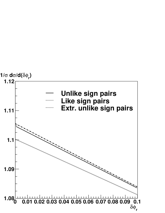
This plot proves that the extrapolation to the small acoplanarity region is insensitive to the total particle pair charge and reflects merely the phase-space for multi-particle production in strong interactions.
11.2 Acceptance Correction
The systematic uncertainties on the acceptance, , are, as before, controlled using the host detector recorded data. The systematic effects are subdivided into two classes: the host detector effects and the luminosity detector effects.
The contribution of the host detector effects such as:
-
•
the losses of the electrons and positrons on the way from the interaction vertex to the luminosity detector fiducial volume – due to hard photon radiation in the material of the beam pipe or of the host detector,
-
•
the biases in the reconstructed momentum scale of those of the host detector reconstructed charged particles which traverse the fiducial volume of luminosity detector,
-
•
the momentum resolution biases,
-
•
the biases in the absolute energy calibration of the LAr calorimeter (important only for the B0 configuration),
-
•
the systematic shifts and resolution biases in the reconstructed azimuthal angles of particles at the interaction vertices,
to the overall measurement error is significantly smaller that the contribution of the luminosity detector effects141414The performance precision targets for the host detector can be relaxed by about an order of magnitude with respect to those necessary for the precision measurements of the parameters of the electroweak models such as e.g. the mass of the W bosons [3]..
The luminosity detector systematic errors were determined by simulating the full data selection and measurement chain with the biases introduced on one-by-one basis. The goal of these simulations was to quantify the impact of each of the luminosity detector systematic effects on the final systematic uncertainty of the measured luminosity. The results of these simulations can be summarised as follows:
-
•
the effect of the luminosity detector misplacement by cm with respect to the nominal -collision point of the LHC bunches translates into a 0.3% luminosity bias,
-
•
the effect of decentering of the luminosity detector with respect to the beam axis () by mm translates into a 0.8% luminosity bias,
-
•
the effect of the relative -tilt of the luminosity detector planes with respect to each other by 1 mrad translates into a 0.1% luminosity bias,
-
•
the effect of misjudgement of the length of the LHC bunches by 1 cm around the central value of 7.5 cm translates into a 0.6% luminosity bias,
-
•
the effect of 0.1% uncertainty on the value of magnetic field in the volume of the host detector tracker and in the fiducial volume of the luminosity detector translates into a 0.4% luminosity bias.
These results show that already for the initial geometrical survey of the luminosity detector, before applying the alignment corrections deduced form the monitoring data, these contributions are below a 1% level. Ultimately the luminosity detector contribution to the overall measurement uncertainty are expected to be driven by the monitoring precision of the length of the LHC bunches. The corresponding biases are expected to be smaller than 1%, provided that the length of the LHC bunches is controlled with a 10% precision.
11.3 Efficiencies
The systematic errors of the efficiencies of the electron/positron identification and of the efficiencies of linking of the luminosity detector tracks to the host detector tracks reflect the purity of the monitoring sample of small invariant mass electrons and positions pairs originated from photons converted in the beam pipe and from the Dalitz decays of neutral pions.
A special care have to be taken to understand the dependence of the electron selection efficiency on the isolation of the electromagnetic cluster. For low and medium luminosity runs this can be done by pre-selecting only those of the minimum bias events which are characterised by a low multiplicity of particles traversing the fiducial volume of the luminosity detector. For the high luminosity runs the efficiency of electron identification decreases and must be monitored in the instantaneous luminosity dependent way.
The impact of the precision of monitoring of on the luminosity measurement systematic uncertainty is expected to be negligible in the low luminosity periods in which the value is approaching 1. For medium luminosities this quantity needs to be precisely monitored using the dedicated samples of random events. The monitoring precision and the corresponding precision of the luminosity measurement depend only on the fraction of the total host detector throughput which can be allocated to these events.
In general systematic errors reflecting the achievable precision of monitoring of the selection efficiencies can be properly estimated using only real data collected at the LHC. They are not expected to contribute significantly to the overall measurement uncertainty for the low luminosity periods. To which extent this can be achieved for the medium and high luminosity runs remains to be demonstrated.
11.4 Theoretical Cross Section
The following source of uncertainties on the theoretical calculations of were taken into account:
-
•
the uncertainty of the elastic form factors of the proton,
-
•
the uncertainty in inelastic form factors of the proton, in the resonance, photo-production, transition and in the deep inelastic regions,
-
•
the uncertainty in the strong and electromagnetic re-scattering cross sections,
-
•
the uncertainty in the higher order electromagnetic radiative corrections.
The first two sources of systematic errors have been analysed and evaluated in our previous paper [6]. It was found that for the pairs in the fiducial volume of the luminosity detector fulfilling the requirement: the present uncertainty on the elastic and inelastic proton form factors translates into a 0.3% precision of the cross section. The size of the re-scattering corrections was analysed and found to be smaller than 0.1% in the above kinematic region. At present, the largest contribution to the total uncertainty comes from the missing calculation of the higher order electromagnetic radiative corrections. Their contribution to the cross sections can reach 1%. There is, however, no other than a technical obstacle in calculations of these corrections – if requested they can be made to the precision significantly better than the form factors related uncertainties [17].
12 Conclusions and Outlook
It has been demonstrated that the proposed method of the luminosity measurement has a large potential to provide the highest achievable precision at hadron colliders. It is based on the electromagnetic collisions of the beam particles in the kinematic regime where they can be treated as point-like leptons and, as a consequence, their collision cross sections can be calculated with a precision approaching the one achieved at the lepton colliders.
The rate of a fraction of these collisions which can be selected and reconstructed using a dedicated luminosity detector is large enough to deliver better that 1% precision over the data collected over less than one month of the data taking with a nominal solenoid current, and a couple of days for the field configuration. The systematic measurement uncertainties can be controlled to a better than 1% precision, by using parasitically, samples of the host detector recorded events. The absolute luminosity measurement procedures are insensitive to the modeling of the collisions mediated by the strong interaction.
The proposed method can be directly applied by the LHCb experiment which can take a full profit from the sizable Lorentz boost of the lepton-pair rest frame allowing to replace the electron-positron pairs by the unlike charge muon pairs which radiate less and can be identified more easily. Thus the LHCb and the host detector distributions could be cross-normalised to a high precision.
The method presented in this series of papers can be directly used in the and collision modes of the LHC collider. For these collision modes the signal-to-background ratio increases, respectively, by and due to the nucleus charge coherence effects. Moreover, a significant increase of the signal rate allows to retain its high statistical precision.
Last but not the least, the scaling of the collider energy dependent rate of the luminosity events can be theoretically controlled with a per-mille precision allowing to cross normalise the data taken at variable collision energies.
This series of papers is only a first step towards its ultimate goal: an implementation of the proposed method in the LHC environment. The preliminary studies presented in this series of papers, and the use of the base-line detector model, are sufficient as a proof of feasibility of the method. Any further steps must be preceded by the acceptation of the method by one of the LHC collaboration. Should this happen the concrete detector design using the host detector preferred technology would be the next step. A conservative approach would be to design a detector for the measurement of the absolute luminosity in the dedicated low/medium luminosity periods. An ambitious programme must have as a target an upgrade the present base-line detector concept such that it can be directly used in the high luminosity period of the machine operation. This is anything but easy but the gain in the precision of all the LHC measurements makes it worth an effort.
References
- [1] M. Mangano, Motivations and precision targets for an accurate luminosity determination, an opening talk at the CERN Lumi-days workshop, CERN, 13-14 Jnuary 2011.
- [2] ATLAS Collab., ATLAS-CONF-2011-116, 19 August 2011.
-
[3]
M. W. Krasny, F. Fayette, W. Placzek, A. Siodmok,
Eur. Phys. J. C51 (2007) 607 (2007) and hep-ph/0702251,
F. Fayette, M.W. Krasny, W. Placzek, A. Siodmok, Eur. Phys. J .C63 (2009) 33 and arXiv:0812.2571 [hep-ph],
M. W. Krasny, F. Dydak, F. Fayette, W. Placzek, A. Siodmok, Eur. Phys. J. C69 (2010) 379 and arXiv:1004.2597 [hep-ex]. - [4] M. W. Krasny, Acta Phys.Polon. B42 (2011) 2133 and arXiv:1108.6163v1 [hep-ph].
- [5] M. W. Krasny, S. Jadach, W. Placzek, Eur. Phys. J. C44 (2005) 333 and hep-ph/0503215.
- [6] M. W. Krasny, J. Chwastowski and K. Słowikowski, Nucl. Instrum. Meth. A584 (2008) 42.
- [7] M. W. Krasny, J. Chwastowski, A. Cyz, and K. Słowikowski, Luminosity Measurement Method for the LHC: The Detector Requirements Studies, June 2010, arXiv:1006.3858 [physics.ins-det].
- [8] ATLAS Collab., G. Aad et al., J. Inst. 3 (2008) S08003, ATLAS Collab., CERN-LHCC-2003-022.
- [9] D0 Collab., V.M. Abazov et al., Nucl. Instrum. Meth. A565 (2006) 463.
- [10] S. P. Baranov, O. Dunger, H. Shooshtari and J.A.M. Vermaseren, LPAIR - A Generator for Lepton Pair Production. Proceedings of Physics at HERA, vol. 3, (1992) 1478.
- [11] T. Sjöstrand, P. Edén, C. Friberg, L. Lönnblad, G. Miu, S. Mrenna and E. Norrbin, Computer Phys. Commun. 135 (2001) 238.
-
[12]
R. Brun et al., Geant 3.21, CERN Program Library Long Writeup W5013,
Geant4 Collab., S. Agostinelli et al., Nucl. Instrum. Meth. A506 (2003) 250,
Geant4 Collab., J. Allison et al., IEEE Trans. Nucl. Science 53 (2006) 270. - [13] The ATLAS Collab., G. Aad et al., Eur. Phys. J. C (2011) 71: 1630.
- [14] S. Myers, private communication
- [15] Proceedings of the Workshop on Fast Timing Detectors: Electronics, Medical and Particle Physics Applications, November 29 – December 1, 2010, eds. J. Chwastowski, P. Le Du, C. Royon, Acta. Phys. Polonica B Proceedings Supplement, vol. 4, no. 1, 2011.
- [16] Y. Giomataris, Ph. Rebourgeard, J-P. Robert and G. Charpak, Nucl. Instr. Meth. A376 (1996) 29.
- [17] M. Skrzypek and S. Jadach, private communication.
- [18] Y.Giomataris, G. Charpak., Nucl. Instr. Meth. A310 (1991) 589.