Background Simulations of the Wide Field Imager of the ATHENA X-Ray Observatory
Abstract
The ATHENA X-ray Observatory-IXO is a planned multinational orbiting X-ray observatory with a focal length of . ATHENA aims to perform pointed observations in an energy range from to with high sensitivity. For high spatial and timing resolution imaging and spectroscopic observations the large DePFET-technology based Wide field Imager (WFI) focal plane detector, providing a field of view of will be the main detector. Based on the actual mechanics, thermal and shielding design we present estimates for the WFI cosmic ray induced background obtained by the use of Monte-Carlo simulations and possible background reduction measures.
I Introduction
The European Space Agency - ESA is currently investigating the ATHENA L-class mission for a next generation X-ray observatory. ATHENA is based on a simplified IXO111International X-ray Observatory: the planned larger predecessor of ATHENA, which would have been jointly built by ESA and NASA.[1, 2] design with the number of instruments and the focal length of the Wolter optics being reduced. One of the two instruments, the Wide Field Imager (WFI) is a DePFET [3, 4] based focal plane pixel detector, allowing spectroscopy in combination with high time and spatial resolution in the energy-range between 0.1 and 15 keV. In order to fulfill the mission goals a high sensitivity is essential, especially to study faint and extended sources. To achieve the required sensitivity a background rate of is required, making a detailed understanding of the detector background induced by cosmic ray particles crucial. During mission design generally extensive Monte-Carlo simulations are used to estimate the detector background in order to optimize shielding components and software rejection algorithms. The Geant4 tool-kit [5, 6] is frequently the tool of choice for this purpose. In the context of our previous work for SIMBOL-X [7, 8, 9, 10, 11] and IXO [12, 13, 14] we present recent results of our estimates for the ATHENA WFI cosmic ray induced background, which demonstrate that DEPFET-technology based detectors are able to achieve the required sensitivity.
II The ATHENA WFI Geometry
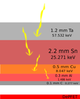
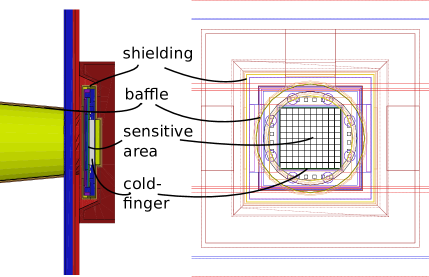
When using Monte-Carlo codes like Geant4 one usually has to find a compromise between the detail level of the detector’s geometrical representation in the simulation and the computing time necessary to achieve the required precision. For the ATHENA WFI we have chosen to model components close to the sensitive area with greater detail as our experience with Simbol-X [15, 16] and IXO missions has shown, that these have significant effect on the detector background. The model shown in Fig. 1 thus includes a detailed model of the detector entrance window additional integrated circuits near the sensitive area. The finer structures of components at larger distances from the sensitive area do not effect the background performance significantly and were therefore simplified in the Geant4 representation. The graded-Z shield shown in Fig. 1 is one of the important WFI design features required to achieve the envisioned low background rates. This shielding effectively suppresses any fluorescence lines from outer-lying materials, eliminating background emissions present in the spectra of previous X-ray telescopes such as XMM Newton [17], Suzaku [18] and Chandra [19]. Not shown in the figure is the cold finger, the thermal coupling to the instruments cooling components, which will attach to the detector on the non-field of view side.
III Estimates on the Cosmic Ray Induced WFI Background
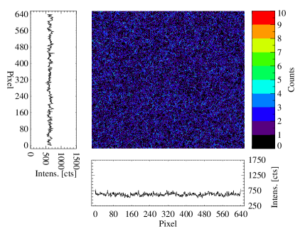
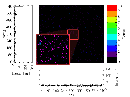
Our current estimates for the ATHENA background rates are given in Table I alongside a comparison of different cold finger implementations and estimates previously obtained from IXO simulations. The rates given in the table are after pattern and MIP222Minimum Ionizing Particle rejection. The effect of these pattern recognition routines, which we use to reject e.g. tracks of MIPs is shown in Fig. 2. The high rejection rates of make an active shielding unnecessary. Because we do not drop the entire frame in which an invalid pattern occurs but only exclude the directly surrounding detector area these routines do not impose an actual ”dead time” on the detector but only a reduction of the per frame pixel count. Translating this area loss into detector availability results in ”dead times” of . This is much less than what would be expected from an anti coincidence of similar performance as it was planned for SIMBOL-X [9, 11].
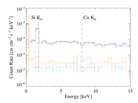
A further reduction of the background requires understanding how much individual particle species contribute to the total background spectrum. As is shown in Fig. 3 secondary electrons resulting from the interaction of the cosmic ray protons with satellite materials dominate the background by an order of magnitude. It is also apparent from the figure that the graded-Z shield is effective at suppressing all but the fluorescence emission. This is to be expected, as the Si emission originates from the sensor material itself and thus cannot be eliminated by the shielding.
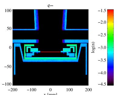
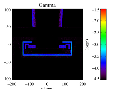
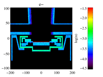
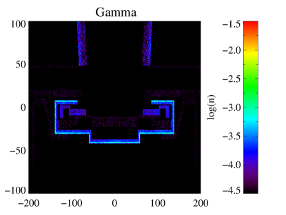
Our simulations show that the dominating source of secondary electrons is the graded-Z shielding as is apparent from Fig. 4 which shows the particle production intensity in a thick slice through the center of the detector. Eliminating the shielding is not an option because it is required for the fluorescence-free background mentioned earlier. Our current and upcoming work is thus concentrating on other possibilities of reducing the secondary electron component.
Baseline w. Coldfinger IXO Fast Slow SiC Graphite HXI no HXI Primaries r/o Rate [fps] Bkgnd flux Increase[%]
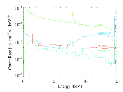
Even without further reduction of the secondary electron component our current estimates already show that the ATHENA WFI will perform better or as good as current state of the art detectors even if it is placed in a harsher background environment. Fig. 5 shows a comparison of the expected WFI background rate and measured dark moon background rates of XMM Newton and Suzaku. In contrast to the Suzaku measurements, which were taken in the intermediate phase of the solar cycle, our estimates are for the solar activity minimum. As minimum solar activity results in a maximum of the cosmic ray flux incident on the satellite we effectively give a worst case estimate.
IV Conclusion and Outlook
We have shown current estimates of the ATHENA WFI background rates, which are low enough for ATHENA to reach its mission design specifications and are better or comparable to present X-ray observatories. Even lower rates may be achievable, as additional potential for optimization exists, especially in the context of reducing the dominating secondary electron background component. Our current and future work will focus on these optimization possibilities.
References
- [1] A. Parmar, “The International X-ray Observatory IXO,” 2008. [Online]. Available: http://www.mpe.mpg.de/ixo/talks.html
- [2] L. Strüder, F. Aschauer, M. Bautz, L. Bombelli, D. Burrows, C. Fiorini, G. Fraser, S. Herrmann, E. Kendziorra, M. Kuster, T. Lauf, P. Lechner, G. Lutz, P. Majewski, A. Meuris, M. Porro, J. Reiffers, R. Richter, A. Santangelo, H. Soltau, A. Stefanescu, C. Tenzer, J. Treis, H. Tsunemi, G. de Vita, and J. Wilms, “The wide-field imager for IXO: status and future activities,” in Society of Photo-Optical Instrumentation Engineers (SPIE) Conference Series, ser. Proceedings of SPIE, vol. 7732, Jul. 2010.
- [3] P. Lechner, R. Hartmann, P. Holl, G. Lutz, N. Meidinger, R. H. Richter, H. Soltau, and L. Strüder, “X-ray imaging spectrometers in present and future satellite missions,” Nuclear Instruments and Methods in Physics Research A, vol. 509, pp. 302–314, Aug. 2003.
- [4] P. Lechner, C. Fiorini, R. Hartmann, J. Kemmer, N. Krause, P. Leutenegger, A. Longoni, H. Soltau, D. Stötter, R. Stötter, L. Strüder, and U. Weber, “Silicon drift detectors for high count rate X-ray spectroscopy at room temperature,” Nuclear Instruments and Methods in Physics Research A, vol. 458, pp. 281–287, Feb. 2001.
- [5] J. Allison, K. Amako, J. Apostolakis, H. Araujo, P. Arce Dubois, M. Asai, G. Barrand, R. Capra, S. Chauvie, R. Chytracek, G. A. P. Cirrone, G. Cooperman, G. Cosmo, G. Cuttone, G. G. Daquino, M. Donszelmann, M. Dressel, G. Folger, F. Foppiano, J. Generowicz, V. Grichine, S. Guatelli, P. Gumplinger, A. Heikkinen, I. Hrivnacova, A. Howard, S. Incerti, V. Ivanchenko, T. Johnson, F. Jones, T. Koi, R. Kokoulin, M. Kossov, H. Kurashige, V. Lara, S. Larsson, F. Lei, O. Link, F. Longo, M. Maire, A. Mantero, B. Mascialino, I. McLaren, P. Mendez Lorenzo, K. Minamimoto, K. Murakami, P. Nieminen, L. Pandola, S. Parlati, L. Peralta, J. Perl, A. Pfeiffer, M. G. Pia, A. Ribon, P. Rodrigues, G. Russo, S. Sadilov, G. Santin, T. Sasaki, D. Smith, N. Starkov, S. Tanaka, E. Tcherniaev, B. Tome, A. Trindade, P. Truscott, L. Urban, M. Verderi, A. Walkden, J. P. Wellisch, D. C. Williams, D. Wright, and H. Yoshida, “Geant4 developments and applications,” IEEE Transactions on Nuclear Science, vol. 53, pp. 270–278, Feb. 2006.
- [6] S. Agostinelli, J. Allison, K. Amako, J. Apostolakis, H. Araujo, P. Arce, M. Asai, D. Axen, S. Banerjee, G. Barrand, F. Behner, L. Bellagamba, J. Boudreau, L. Broglia, A. Brunengo, H. Burkhardt, S. Chauvie, J. Chuma, R. Chytracek, G. Cooperman, G. Cosmo, P. Degtyarenko, A. dell’Acqua, G. Depaola, D. Dietrich, R. Enami, A. Feliciello, C. Ferguson, H. Fesefeldt, G. Folger, F. Foppiano, A. Forti, S. Garelli, S. Giani, R. Giannitrapani, D. Gibin, J. J. Gómez Cadenas, I. González, G. Gracia Abril, G. Greeniaus, W. Greiner, V. Grichine, A. Grossheim, S. Guatelli, P. Gumplinger, R. Hamatsu, K. Hashimoto, H. Hasui, A. Heikkinen, A. Howard, V. Ivanchenko, A. Johnson, F. W. Jones, J. Kallenbach, N. Kanaya, M. Kawabata, Y. Kawabata, M. Kawaguti, S. Kelner, P. Kent, A. Kimura, T. Kodama, R. Kokoulin, M. Kossov, H. Kurashige, E. Lamanna, T. Lampén, V. Lara, V. Lefebure, F. Lei, M. Liendl, W. Lockman, F. Longo, S. Magni, M. Maire, E. Medernach, K. Minamimoto, P. Mora de Freitas, Y. Morita, K. Murakami, M. Nagamatu, R. Nartallo, P. Nieminen, T. Nishimura, K. Ohtsubo, M. Okamura, S. O’Neale, Y. Oohata, K. Paech, J. Perl, A. Pfeiffer, M. G. Pia, F. Ranjard, A. Rybin, S. Sadilov, E. di Salvo, G. Santin, T. Sasaki, N. Savvas, Y. Sawada, S. Scherer, S. Sei, V. Sirotenko, D. Smith, N. Starkov, H. Stoecker, J. Sulkimo, M. Takahata, S. Tanaka, E. Tcherniaev, E. Safai Tehrani, M. Tropeano, P. Truscott, H. Uno, L. Urban, P. Urban, M. Verderi, A. Walkden, W. Wander, H. Weber, J. P. Wellisch, T. Wenaus, D. C. Williams, D. Wright, T. Yamada, H. Yoshida, and D. Zschiesche, “Geant4- a simulation toolkit,” Nucl. Instrum. Methods Phys. Res., Sect. A, vol. 506, pp. 250–303, Jul. 2003. [Online]. Available: http://www.cern.ch/geant4
- [7] C. Tenzer, E. Kendziorra, A. Santangelo, M. Kuster, P. Ferrando, P. Laurent, A. Claret, and R. Chipaux, “Monte carlo simulations of stacked x-ray detectors as designed for simbol-x,” in Space Telescopes and Instrumentation II: Ultraviolet to Gamma Ray, ser. Proceedings of SPIE, M. J. L. Turner and G. Hasinger, Eds., vol. 6266, Jul. 2006.
- [8] C. Klose, “Simulation zum Detektorhintergrund des Röntgensatelliten SIMBOL-X,” Master’s thesis, TU Darmstadt, May 2007, Diploma Thesis.
- [9] C. Tenzer, U. Briel, A. Bulgarelli, R. Chipaux, A. Claret, G. Cusumano, E. Dell’Orto, V. Fioretti, L. Foschini, S. Hauf, E. Kendziorra, M. Kuster, P. Laurent, and A. Tiengo, “Status of the simbol-x background simulation activities,” in American Institute of Physics Conference Series, ser. American Institute of Physics Conference Series, J. Rodriguez & P. Ferrando, Ed., vol. 1126, May 2009, pp. 75–78.
- [10] S. Hauf, “Simulation on the SIMBOL-X Detector Background,” Master’s thesis, TU Darmstadt, Mar. 2009.
- [11] ——, “Simulating and Optimizing the Simbol-X Detector Background,” Votrag am 6. Geant 4 Space Users Workshop, Madrid, Spanien, Mai 2009.
- [12] S. Hauf, M. Kuster, D. Hoffmann, M. Pia, G. Weidenspointner, A. Zoglauer, and Z. Bell, “Progress and Validation of Geant4 Based Radioactive Decay Simulation Using the Examples of Simbol-X and IXO,” ser. IEEE NSS MIC 2009, Orlando, 2009.
- [13] S. Hauf, “Simulationen zum IXO WFI Detektorhintergrund,” DPG Frühjahrstagung, Bonn, April 2010.
- [14] ——, “Current Status of IXO WFI Background Simulations,” Technical Note for HLL and ESTEC, Juli 2010.
- [15] P. Ferrando, “Simbol-x, an x-ray telescope for the 0.5-70 kev range,” in SF2A-2002: Semaine de l’Astrophysique Francaise, F. Combes and D. Barret, Eds., Jun. 2002, pp. 271–+.
- [16] ——, “SIMBOL-X Telescope: Reference Configuration No. 1, Scientific Elements,” 2006, jSMG-PhF-10-10-06.
- [17] L. Strüder, J. Englhauser, R. Hartmann, P. Holl, N. Meidinger, H. Soltau, U. Briel, K. Dennerl, M. Freyberg, F. Haberl, G. Hartner, E. Pfeffermann, T. Stadlbauer, and E. Kendziorra, “pnccds on xmm-newton—42 months in orbit,” Nuclear Instruments and Methods in Physics Research Section A: Accelerators, Spectrometers, Detectors and Associated Equipment, vol. 512, no. 1-2, pp. 386 – 400, 2003, ¡ce:title¿Proceedings of the 9th European Symposium on Semiconductor Detectors: New Developments on Radiation Detectors¡/ce:title¿. [Online]. Available: http://www.sciencedirect.com/science/article/pii/S016890020301917X
- [18] K. Mitsuda, M. Bautz, H. Inoue, R. L. Kelley, K. Koyama, H. Kunieda, K. Makishima, Y. Ogawara, R. Petre, T. Takahashi, H. Tsunemi, N. E. White, N. Anabuki, L. Angelini, K. Arnaud, H. Awaki, A. Bamba, K. Boyce, G. V. Brown, K.-W. Chan, J. Cottam, T. Dotani, J. Doty, K. Ebisawa, Y. Ezoe, A. C. Fabian, E. Figueroa, R. Fujimoto, Y. Fukazawa, T. Furusho, A. Furuzawa, K. Gendreau, R. E. Griffiths, Y. Haba, K. Hamaguchi, I. Harrus, G. Hasinger, I. Hatsukade, K. Hayashida, P. J. Henry, J. S. Hiraga, S. S. Holt, A. Hornschemeier, J. P. Hughes, U. Hwang, M. Ishida, Y. Ishisaki, N. Isobe, M. Itoh, N. Iyomoto, S. M. Kahn, T. Kamae, H. Katagiri, J. Kataoka, H. Katayama, N. Kawai, C. Kilbourne, K. Kinugasa, S. Kissel, S. Kitamoto, M. Kohama, T. Kohmura, M. Kokubun, T. Kotani, J. Kotoku, A. Kubota, G. M. Madejski, Y. Maeda, F. Makino, A. Markowitz, C. Matsumoto, H. Matsumoto, M. Matsuoka, K. Matsushita, D. McCammon, T. Mihara, K. Misaki, E. Miyata, T. Mizuno, K. Mori, H. Mori, M. Morii, H. Moseley, K. Mukai, H. Murakami, T. Murakami, R. Mushotzky, F. Nagase, M. Namiki, H. Negoro, K. Nakazawa, J. A. Nousek, T. Okajima, Y. Ogasaka, T. Ohashi, T. Oshima, N. Ota, M. Ozaki, H. Ozawa, A. N. Parmar, W. D. Pence, F. S. Porter, J. N. Reeves, G. R. Ricker, I. Sakurai, W. T. Sanders, A. Senda, P. Serlemitsos, R. Shibata, Y. Soong, R. Smith, M. Suzuki, A. E. Szymkowiak, H. Takahashi, T. Tamagawa, K. Tamura, T. Tamura, Y. Tanaka, M. Tashiro, Y. Tawara, Y. Terada, Y. Terashima, H. Tomida, K. Torii, Y. Tsuboi, M. Tsujimoto, T. G. Tsuru, M. J. L. . Turner, Y. Ueda, S. Ueno, M. Ueno, S. Uno, Y. Urata, S. Watanabe, N. Yamamoto, K. Yamaoka, N. Y. Yamasaki, K. Yamashita, M. Yamauchi, S. Yamauchi, T. Yaqoob, D. Yonetoku, and A. Yoshida, “The X-Ray Observatory Suzaku,” Publications of the Astronomical Society of Japan, vol. 59, pp. 1–7, Jan. 2007.
- [19] R. C. Hickox and M. Markevitch, “Absolute Measurement of the Unresolved Cosmic X-Ray Background in the 0.5-8 keV Band with Chandra,” The Astrophysical Journal, vol. 645, no. 1, p. 95, 2006. [Online]. Available: http://stacks.iop.org/0004-637X/645/i=1/a=95
- [20] A. Stefanescu, M. Bautz, D. Burrows, L. Bombelli, C. Fiorini, G. Fraser, K. Heinzinger, S. Hermann, M. Kuster, T. Lauf, P. Lechner, G. Lutz, P. Majewski, S. Murray, M. Porrp, R. Richer, A. Santangelo, G. Schaller, M. Schnecke, F. Schoper, H. Soltau, L. Strüder, J. Treis, H. Tsunemi, G. de Vita, and J. Wilms, “The Wide-Field Imager of the International X-ray Observatory,” Nucl. Instrum. Methods Phys. Res., Sect. A, vol. 624, pp. 533–539, 2010.
- [21] P. Lechner, R. Hartmann, P. Holl, G. Lutz, N. Meidinger, R. H. Richter, H. Soltau, and L. Strüder, “X-ray Imaging Spectrometers in Present and Future Satellite Missions,” Nucl. Instrum. Methods Phys. Res., Sect. A, vol. 509, pp. 302–314, Aug. 2003.
- [22] A. Tylka, W. Dietrich, P. Boberg, E. Smith, J. Adams, Jr., B. Brownstein, E. Flueckinger, E. Petersen, S. M.A., and D. Smart, “Creme96: A revision of the cosmic ray effects on micro-electronics code,” IEEE Trans. Nucl. Sci., pp. 2150–2160, 1997.