Controlled spin domain creation by phase separation
Abstract
We demonstrate a method of controlled creation of spin domains in spin-1 antiferromagnetic Bose-Einstein condensates. The method exploits the phenomenon of phase separation of spin components in an external potential. By using an appropriate time dependent potential, a composition of spin domains can be created, as we demonstrate in the particular cases of a double well and a periodic potential. In contrast to other methods, which rely on spatially inhomogeneous magnetic fields, here the domain structure is completely determined by the optical fields, which makes the method versatile and reconfigurable. It allows for creation of domains of various sizes, with the spatial resolution limited by the spin healing length only.
pacs:
03.75.Mn, 03.75.Hh, 67.85.Bc, 67.85.FgI Introduction
Bose-Einstein condensates with spin degrees of freedom Ho attracted in recent years great interest due to the unique possibility of exploring fundamental concepts of quantum mechanics in a remarkably controllable and tunable environment. The ability to generate spin squeezing and entanglement Entanglement makes spinor Bose gases promising candidates for applications as quantum simulators QS , in quantum information QI , and for precise measurements Measurement . Moreover, spinor condensates were successfully used to recreate many of the phenomena of condensed matter physics in experiments displaying an unprecedented level of control over the quantum system. In particular, spin domains Stenger_Nat_1998 ; Quenched ; Ketterle_Metastable , spin mixing Mixing , and spin vortices Ketterle_Coreless were predicted and observed.
The ability to create spin domains is a crucial component of applications including data storage and spin based logic implementation DomainWallsApps . To date, domain structures in Bose-Einstein condensates were created in a controllable way using inhomogeneous magnetic fields Stenger_Nat_1998 . In principle, these can be induced by magnetic coils, electronic chips or permanent magnets MagneticDomainCreation . However, both the spatial resolution of this method and the ability to produce arbitrarily shaped, reconfigurable spin domain structures is severely limited.
In recent papers Matuszewski_PS ; Matuszewski_Trap , we considered the possibility of phase separation in the ground state of spinor condensates. We demonstrated that this phenomenon can take place in both antiferromagnetic and ferromagnetic condensates in external potentials. In this paper, we exploit the phenomenon of phase separation to propose a method of controlled creation of metastable spin domain states with a chosen spatial spin structure. It consists of applying an appropriately designed optical potential, which is subsequently slowly relaxed towards the desired final trapping potential. In contrast to the other method, relying on magnetic field gradients to separate spin components, our method uses more easily reconfigurable optical laser fields to shape the spatial structure. Importantly, these structures are not “pinned” by local extrema of the magnetic field. An additional advantage is the high spatial resolution, which we demonstrate to be generally limited only by the spin healing length of the condensate.
The paper is organized as follows. Section II reviews the mean-field model of a spin-1 condensate in a homogeneous magnetic field. In Section III we present numerical simulations of the spin domain creation process. In Section IV we discuss practical limitations of the proposed method using both analytical and numerical approach. Section V concludes the paper.
II Model
We consider a spin-1 Bose-Einstein condensate in a homogeneous magnetic field pointing along the axis. We apply the mean field approximation, which describes dilute Bose-Einstein condensates at zero temperature. In spinor condensates, ground states can substantially deviate from the mean field solutions even at zero temperature due to large quantum fluctuations NonMeanField . However, it was shown that the introduction of a weak magnetic field restores the validity of the mean-field model. We start with the Hamiltonian ,
| (1) |
where are the wave functions of atoms in magnetic sublevels , is the atomic mass, is an external potential and is the total atom density. The asymmetric (spin dependent) part of the Hamiltonian is given by
| (2) |
where is the Zeeman energy shift for state and the spin density is,
| (3) |
where are the spin-1 matrices Isoshima_PRA_1999 and . The spin-independent and spin-dependent interaction coefficients are given by and , where is the s-wave scattering length for colliding atoms with total spin . The total number of atoms and the total magnetization in the direction of the magnetic field
| (4) | ||||
| (5) |
are conserved quantities. The Zeeman energy shift for each of the components, can be calculated using the Breit-Rabi formula Wuster
| (6) |
where is the hyperfine energy splitting at zero magnetic field, , where is the Bohr magneton, and are the nuclear and electronic g-factors, and is the magnetic field strength. The linear part of the Zeeman effect gives rise to an overall shift of the energy, and so we can remove it with the transformation
| (7) |
This transformation is equivalent to the removal of the Larmor precession of the spin vector around the axis Matuszewski_PRA_2008 . We thus consider only the effects of the quadratic Zeeman shift. For sufficiently weak magnetic field we can approximate it by , which is positive for 87Rb and 23Na condensates.
The Hamiltonian (1) gives rise to the Gross-Pitaevskii equations describing the mean-field dynamics of the system
| (8) | ||||
where is given by .
By comparing the kinetic energy with the interaction energy, we can determine the healing length and the spin healing length . These quantities give the length scales of spatial variations in the condensate profile induced by the spin-independent or spin-dependent interactions, respectively. Analogously, we define the magnetic healing length as .
In spin-1 condensates created to date, the and scattering lengths have similar magnitudes. The spin-dependent interaction coefficient is then much smaller than its spin-independent counterpart . For example, this ratio is about 1:30 in a 23Na condensate and 1:220 in a 87Rb condensate far from Feshbach resonances Beata . Consequently, changing the total density requires much more energy than changing the relative populations of spin states . In our considerations we will assume that the total atom density profile is close to the Thomas-Fermi profile for a given potential .
III Spin domain creation
In Refs. Matuszewski_PS ; Matuszewski_Trap we demonstrated that in the presence of a homogeneous magnetic field, a spin-imbalanced (magnetized) antiferromagnetic condensate is subject to phase separation in the ground state resulting in separate spin domains. The spin domains align according to a simple rule; the magnetized domains reside in the regions with the lowest density, while the unmagnetized domains fill the areas of high density. In this way, the nonlinear spin energy of the antiferromagnetic condensate is minimized for a given total magnetization. In this work, we will show that one can use this property to shape the spatial distribution of spin with an appropriate time varying external potential.
We consider a quasi-1D sodium condensate trapped in an elongated harmonic potential described by the 1D version of Eqs. (8) Matuszewski_PS with rescaled interaction coefficients , where is the transverse trapping frequency. The Fermi radius of the transverse trapping potential is smaller than the spin healing length, and the nonlinear energy scale is much smaller than the transverse trap energy scale, which allows us to reduce the problem to one spatial dimension Beata ; NPSE . To create a double well potential, we add a Gaussian potential barrier that can be realized eg. by an additional blue-detuned laser beam
| (9) |
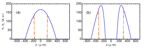
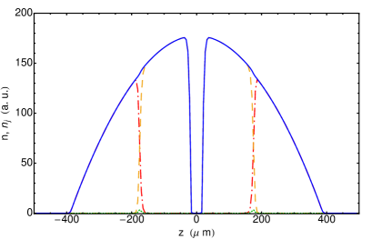
In the absence of the barrier, and under certain experimental conditions Matuszewski_PS , the ground state is characterized by spatial separation of the and atoms (or , depending on the magnetization), see Fig. 1(a). After switching the barrier on, the condensate splits in an effective longitudinal double well potential into two symmetric parts. We note that the ground state now has the structure corresponding to Fig. 2(a). However, the result of a slow increase of the barrier on the timescale scale of several seconds results in a different state, where inner domains are absent on both sides of the barrier. The difference between Fig. 1(b) and Fig. 2(a) is a result of the strong spin immiscibility Ketterle_Metastable of the atoms that suppresses the tunnelling of atoms through the atoms. The final state is thus a metastable state, but practically stable on the relevant experimental timescales.
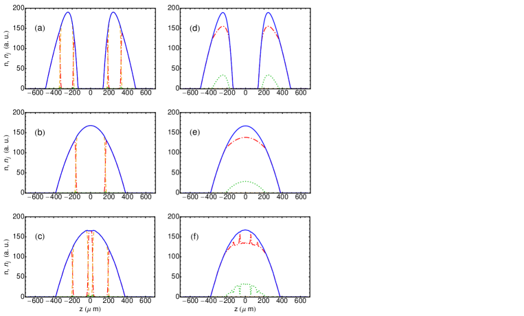
A yet more intriguing effect can occur when the condensate is prepared in the ground state of the double well potential (with the barrier on), Fig. 2(a), and after gradually lowering the potential barrier. The condensate, instead of evolving towards the single-well ground state, Fig. 2(b), creates another kind of a metastable state, with five alternating spin domains of and atoms shown in Fig. 2(c). Again, we checked that these spin domains are perfectly stable on the timescales as long as several seconds due to suppressed tunneling. In principle, by applying several potential barriers with certain parameters, it is possible to create a given number of stable spin domains of various sizes.
We note that the above spin-domain creation scenario is possible only for domains which consist of immiscible atoms. The phase separation of and atoms is a feature of antiferromagnetic spin-1 condensates in a relatively strong magnetic field Matuszewski_PS . In the weaker field regime, the spin-imbalanced antiferromagnetic condensate generally consists of and atoms, which are miscible. In result, the spin domains do not separate, and the slow process always results in a state close to the ground state of the system, as shown in Fig. 2(d)-(f).
Furthermore, we consider a condensate placed in a periodic optical potential
| (10) |
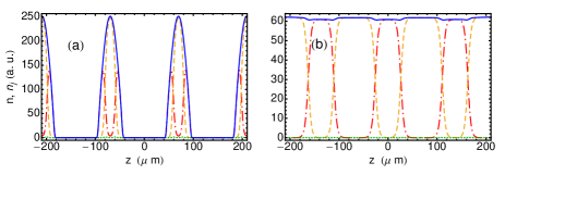
with being the lattice period. We simulate the dynamics of the condensate with periodic boundary conditions, which can be experimentally realized eg. with a ring-shaped trapping geometry Toroidal . Analogously as in the previous case, we start with a condensate with the optical lattice switched on. the density and spin pattern is shown in Fig. 3(a). By gradually decreasing the optical lattice strength, we arrive at a metastable state depicted in Fig. 3(b), composed of multiple and spin domains. This state is also stable on the timescales of the order of seconds. We note that by modifying the lattice potential through introducing higher order Fourier components, we are also able to adjust the size of individual domains.
IV Limitations of the method
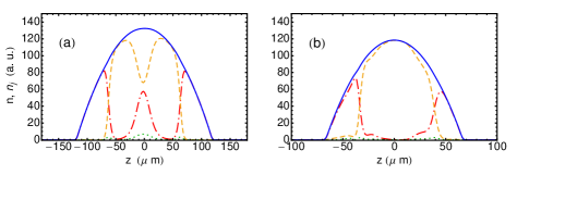
We now discuss some limitations of the above method of domain creation. As we mentioned above, these metastable states are stable on an experimentally relevant time scale due to the suppression of tunneling. However, the tunneling rate depends on the system parameters such as the trap size and atom number. In Fig. 4 we show the result of adiabatic barrier removal for tighter harmonic traps with Hz (a) and Hz (b). The atom number is here reduced proportionally to keep a similar density profile. Thus, an analogous domain structure as in Fig. 2(c) is expected. Since the healing length, determining the size of domain boundaries (see below) is almost the same in all cases due to a similar atom density profile, we expect the tunneling to be more significant in smaller systems. Indeed, the effect of the tunneling is clearly visible when comparing Fig. 2(c) with Fig. 4(a) and (b). With the decreasing distance between the domains the state becomes unstable, see Fig. 4(a). In the case of the tightest trap, Fig. 4(b), the middle domain dissolves completely and the single-well ground state is obtained.
The tunneling rate can be estimated analytically along the lines of Ref. Ketterle_Metastable , where the case of a spatially varying magnetic field potential was considered. Here, we apply a similar method to the case of a spatially varying external potential. First, we assume that the condensate separates into two components, one of them being and the other either or , and neglect the influence of the third component. The potential energy for the atoms is given by
| (11) |
where is the other present component. The interaction constants in an condensate are and . We estimate the tunneling rate of atoms from the middle domain in a structure similar as the one shown in Fig. 2(c) towards the edges of the condensate. The chemical potential of atoms in the middle domain is . We assume that the density of component is negligible. Analogously, in the neighboring domain the atoms have chemical potential equal to . The atoms which tunnel through this domain feel the potential . Their density profile can be calculated in the WKB approximation
| (12) | ||||
where the decay of the density means that on the right side of the middle domain and on the left side. In the simplest approximation, does not vary significantly and the decay is exponential. Taking into account the pressure balance at the domain boundary, , we can estimate the decay as with , where is the spin healing length. We can now write down the formula for the tunneling rate in the metastable state
| (13) |
where is the distance between the domains and is the attempt rate , with being the speed of sound averaged over the transverse density profile Ketterle_Metastable . This indicates that the tunneling is greatly suppressed when the distance between the domains is larger than the spin healing length, which determines the spin domain boundary width through the coefficient . In Table 1 we show the ratio of the calculated amount of atoms that tunnel through to the total number of atoms in the middle domain. In the case of the tightest trap, the tunneling over the time of the evolution would exceed the number of available atoms, which explains the absence of a metastable state.
| Trap frequency | |
|---|---|
| Hz | |
| Hz | |
| Hz |
The second limitation of the method is related to the minimal size of a domain. For illustration, in Fig. 5 we present the condensate ground state in the double well potential as in Fig. 2(a), but created with a very narrow Gaussian barrier. In this case the inner domains of atoms are absent, and consequently the slow decrease of the barrier height leads to the ground state, Fig. 2(b), instead of the metastable state, Fig. 2(c). The reason for the absence of the domains is the very steep slope of the density profile close to the barrier. According to Ref. Matuszewski_Trap , in the local density approximation (LDA), the spin state at a given point is determined by the value of the atom density at this point. The atoms can reside only in a very narrow region on the density slope where it is smaller than a certain value. If this region is smaller than twice the spin healing length, the domain cannot form. The approximate size of this region can be estimated as twice the distance between the point of maximum density and half the maximum density,
| (14) |
We confirmed through systematic numerical simulations with varying barrier size that with a good accuracy the inner domains appear when becomes larger than .
V Conclusions
In conclusion, we demonstrated a method of controlled creation of metastable spin domains in an antiferromagnetic condensate in a homogeneous magnetic field. The method exploits the phase separation of spin components in an external potential. In contrast to other methods, which rely on the spatially varying magnetic fields, the domain structure is here completely determined by optical fields, which makes this method more versatile and reconfigurable. Additionally, the method allows for creation of domains of various sizes, with spatial resolution limited by the spin healing length only.
Acknowledgements.
This work was supported by the Foundation for Polish Science through the “Homing Plus” programme and by the EU project NAMEQUAM.References
- (1) T.-L. Ho, Phys. Rev. Lett. 81, 742 (1998); T. Ohmi and K. Machida, J. Phys. Soc. Jpn. 67, 1822 (1998).
- (2) H. Pu and P. Meystre, Phys. Rev. Lett. 85, 3987 (2000); J. Estève, C. Gross, A. Weller, S. Giovanazzi, and M. K. Oberthaler, Nature 455, 1216 (2008).
- (3) S. Lloyd, Science 273, 1073 (1996).
- (4) D. DiVincenzo, Fortschr. Phys. 48, 771 (2000).
- (5) C. Gross, T. Zibold, E. Nicklas, J. Estève, and M. K. Oberthaler, Nature 464, 1165 (2010); M. F. Riedel, P. Böhi, Y. Li, T. W. Hänsch, A. Sinatra, and P. Treutlein, Nature 464, 1170 (2010).
- (6) J. Stenger, S. Inouye, D. M. Stamper-Kurn, H.-J. Miesner, A. P. Chikkatur, and W. Ketterle, Nature (London) 396, 345 (1998).
- (7) H.-J. Miesner, D. M. Stamper-Kurn, J. Stenger, S. Inouye, A. P. Chikkatur, and W. Ketterle, Phys. Rev. Lett. 82, 2228 (1999).
- (8) L. E. Sadler, J. M. Higbie, S. R. Leslie, M. Vengalattore, and D. M. Stamper-Kurn, Nature (London) 443, 312 (2006); M. Matuszewski, Phys. Rev. Lett. 105, 020405 (2010).
- (9) H. Pu, C. K. Law, S. Raghavan, J. H. Eberly, and N. P. Bigelow, Phys. Rev. A 60, 1463 (1999); A. T. Black, E. Gomez, L. D. Turner, S. Jung, and P. D. Lett, Phys. Rev. Lett. 99, 070403 (2007); M.-S. Chang, C. D. Hamley, M. D. Barrett, J. A. Sauer, K. M. Fortier, W. Zhang, L. You, and M. S. Chapman, Phys. Rev. Lett. 92, 140403 (2004).
- (10) A. E. Leanhardt, Y. Shin, D. Kielpinski, D. E. Pritchard, and W. Ketterle, Phys. Rev. Lett. 90, 140403 (2003).
- (11) S. S. P. Parkin, M. Hayashi, and L. Thomas, Science 320, 190 (2008); D. A. Allwood, Gang Xiong, M. D. Cooke, C. C. Faulkner, D. Atkinson, N. Vernier and R. P. Cowburn, Science 296, 2003 (2002).
- (12) W. Hänsel, P. Hommelhoff, T. W. Hänsch and J. Reichel, Nature 413 498 (2001). C. D. J. Sinclair, E. A. Curtis, J. A. Retter, B. V. Hall, I. Llorente Garcia, S. Eriksson, B. E Sauer and E. A. Hinds, J. Phys. Conf. Ser. 19 74 (2005).
- (13) M. Matuszewski, T. J. Alexander, and Y. S. Kivshar, Phys. Rev. A 80, 023602 (2009).
- (14) M. Matuszewski, Phys. Rev. A 82, 053630 (2010).
- (15) C. K. Law, H. Pu, and N. P. Bigelow, Phys. Rev. Lett. 81, 5257 (1998); M. Koashi and M. Ueda, Phys. Rev. Lett. 84, 1066 (2000); T.-L. Ho and S.-K. Yip, Phys. Rev. Lett. 84, 4031 (2000).
- (16) T. Isoshima, K. Machida and T. Ohmi, Phys. Rev. A 60, 4857 (1999).
- (17) S. Wüster, T. E. Argue, and C. M. Savage, Phys. Rev. A 72, 043616 (2005).
- (18) M. Matuszewski, T. J. Alexander, and Y. S. Kivshar, Phys. Rev. A 78, 023632 (2008).
- (19) B.J. Da̧browska-Wüster, E. A. Ostrovskaya, T. J. Alexander, and Y. S. Kivshar, Phys. Rev. A 75, 023617 (2007).
- (20) L. Salasnich, A. Parola, and L. Reatto, Phys. Rev. A 65, 043614 (2002); W. Zhang and L. You, Phys. Rev. A 71, 025603 (2005).
- (21) E. M. Wright, J. Arlt, and K. Dholakia, Phys. Rev. A 63, 013608 (2000); K. E. Strecker, G. B. Partridge, A. G. Truscott, and R. G. Hulet, Nature 417, 150 (2002); S. K. Schnelle, E. D. van Ooijen, M. J. Davis, N. R. Heckenberg, and H. Rubinsztein-Dunlop, Opt. Express, 16, 1405 (2008).