Thermal noise in optical cavities revisited
Abstract
Thermal noise of optical reference cavities sets a fundamental limit to the frequency instability of ultra-stable lasers. Using Levin’s formulation of the fluctuation-dissipation theorem we correct the analytical estimate for the spacer contribution given by Numata et al. num04 . For detailed analysis finite-element calculations of the thermal noise focusing on the spacer geometry, support structure and the usage of different materials have been carried out. We find that the increased dissipation close to the contact area between spacer and mirrors can contribute significantly to the thermal noise. From an estimate of the support structure contribution we give guidelines for a low-noise mounting of the cavity. For mixed-material cavities we show that the thermal expansion can be compensated without deteriorating the thermal noise.
I Introduction
Ultrastable optical cavities have become a standard tool for stabilizing laser systems needed e.g. for high-resolution spectroscopy, optical clocks ros08 ; lud08 , optical microwave generation bar05 ; mil09a ; lip09 and coherent optical frequency transfer wil08a ; jia08 ; ter09 . State-of-the-art cavity-stabilized laser systems show linewidths below 1 Hz and fractional frequency instabilities between and at one second you99 ; sto06 ; not06 ; lud07 ; web08 ; dub09 ; lod10 ; mil09 .
The fractional length stability of ultra-stable cavities is limited by inevitable thermal noise in the cavity materials and a world-wide effort is ongoing to reduce this limitation. An efficient way of calculating thermal noise has been proposed by Levin lev98 , applying the fluctuation-dissipation theorem. Following his so-called “direct approach” for optical cavities, a set of equations was given by Numata et al. num04 for estimating the noise contribution of spacer, substrates and coatings.
The equations give a good estimate of the thermal noise arising from the mirrors which have been identified as the dominant source of noise for cavities with mirror substrates made of the widely used ultra low expansion glass (ULE). In state-of-the-art optical cavities however, substrate materials of higher mechanical quality are being used leg10 ; mil09 ; kes10 ; not95 . For these optical cavities a fractional instability on a level of a few has been shown. At this level the spacer contribution is non-negligible and has to be calculated by numerical modeling. In this publication we describe the mechanisms of dissipation in an optical cavity with focus on the spacer contribution, including the support structure, the usage of different materials and the spacer geometry. We discuss current cavity designs with respect to their thermal noise budget and, where possible, will give construction guidelines for future cavity designs.
In section II we introduce the theoretical framework used for the simulations. We apply the simulation to a typical cavity design in section III.1 and discuss deviations from the analytical estimate for the spacer contribution. In section III.2 we show that also the cavity support can lead to non-negligible contribution to the spacer thermal noise. In the final section III.3 we focus on the thermal noise floor of mixed-material cavities.
II Theoretical framework
Thermal noise in laser mirrors has been investigated in great detail with respect to gravitational wave detection lev98 ; bon98 ; bra99 ; liu00 ; bra03 ; fej04 ; eva08 ; lev08a . A variety of thermal noise sources have been identified so far gor08a , Brownian thermal noise being the most dominant one. An effective way to estimate thermal noise has been first proposed by Levin lev98 , following the fluctuation-dissipation theorem as introduced by Callen and Welton cal51 . The effect of Brownian motion thermal noise on the length stability of ultra-stable optical resonators has been pointed out by Numata et al. num04 following Levin’s so called “direct approach” lev98 . This concept is illustrated for clearness in the following.
For optical resonators the generalized coordinate describing the length fluctuations is the averaged distance between the two cavity mirrors as probed by the laser field. According to the fluctuation-dissipation theorem, the spectral density of the thermal fluctuations of is calculated by applying a corresponding conjugate force with amplitude to each mirror surface leading to
| (1) |
where denotes the temperature and the Boltzmann constant. The term denotes the time-averaged dissipated power in the system when an oscillatory force with amplitude and frequency is applied. To calculate the thermal noise for a homogeneously distributed internal loss the term is then expressed by
| (2) |
where denotes the maximum elastic strain energy and and the loss angle of the system. The total dissipated power and thus the noise of the cavity length can be described as the sum of the contributions from spacer , two substrates and two coatings .
| (3) |
The power spectral density of length fluctuations can easily be converted to fractional frequency fluctuations . The instability of the fluctuations in the time-domain is conventionally characterized by the Allan-deviation all66 of the fractional frequency fluctuations . The noise of equation (3) (flicker frequency noise) leads to a constant Allan deviation
| (4) |
In a typical reference cavity the differential mirror displacement is probed by a Gaussian laser beam with a beam radius . Consequently a pressure distribution,
| (5) |
has to be applied to the two mirrors with opposite sign to drive the excitation.
If the mirror is treated as an infinite half space the contribution of the substrate is given by lev98 ; bon98
| (6) |
where denotes Young’s modulus and Poisson’s ratio of the substrate material. Bondu et al. bon98 have later refined the formula for a finite-size mirror, revealing that a long “bar-shaped” mirror substrate with a thickness larger than the mirror radius should be preferred to a “gong-shaped” substrate. However, for typical cavity geometries the beam waist is much smaller than the mirror dimensions and therefore the mirror can be approximated in good accuracy by a infinite half-space.
The coating contribution to Brownian motion thermal noise is typically estimated by treating the coating as a thin layer of thickness on the substrate’s front face har02b ; fej04 ; eva08 . Assuming a homogeneous loss angle and similar elasticity of coating and substrate as in the case of Ti2O5/SiO2 coatings on ULE or fused silica, the coating contribution reduces to
| (7) |
For materials with large Young’s modulus such as silicon or sapphire the thermal noise is dominated by the loss angle for strains perpendicular to the surface which is difficult to access experimentally (see discussion in har02b for details).
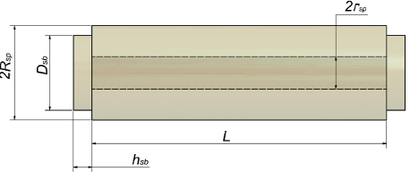
As a rough estimate for the spacer contribution to the cavity noise the thermal fluctuations of the length of a cylinder, averaged over the whole front face area, are calculated. A cylinder of length , radius and central bore radius is assumed. Levin’s direct approach then demands a pressure uniformly distributed across its front faces with area , leading to an elastic energy of
| (8) |
According to equations (1) and (2) the thermal fluctuations of the spacer length averaged over the full cross-section of the front faces are
| (9) |
Note, that this estimate differs from the result given by Numata et al. in two ways. Firstly, equation (8) takes into account that the front face area of the spacer is reduced by the area of the central bore. Secondly, our result is a factor of larger than the result by Numata et al. To derive their equation the authors used the formula for the position fluctuations of one end of a free, elastic bar yam00 . This approach is widely employed for single mirrors in interferometers for gravitational wave astronomy. To calculate the length fluctuations of the spacer of a Fabry-Perot interferometer the authors simply added the fluctuations from both sides which assumes that those are uncorrelated. According to Levin’s direct approach the calculation of the length fluctuation requires to apply opposite forces simultaneously to both ends. Consequently this approach automatically takes into account correlations from both ends which were neglected in num04 .
According to the model described by equation (9), the noise can be minimized by distributing the stress on a large cross section. However, for mirrors smaller than the diameter of the spacer, this approximation is not valid and for a reliable calculation of the spacer contribution of the thermal noise finite element methods (FEM) have to be applied as described in the next section.
III Simulations
For the calculations presented in the following chapter, the software package COMSOL comsol has been used. The general cavity geometry is depicted in Figure 1.
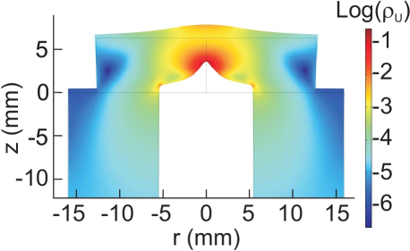
The calculations have been carried out in axial symmetry. Because of mirror symmetry with respect to the cavity mid plane, half a cavity was simulated. Figure 2 shows the calculated cavity deformation under the pressure distribution of equation (5) assuming the parameters given in Table 1. For illustration purposes a beam waist of 2 mm has been chosen. We quote our results in terms of elastic strain energies. For ULE a strain energy of 1 nJ corresponds to a length fluctuation mHz at 1 Hz and a corresponding Allan deviation of at 1 second for a cavity length of 100 mm.
The shape of the deformation of the substrate reflects the Gaussian beam profile. The majority of the elastic strain energy is stored in the cavity substrate. Strong local deformations occur at the boundary between substrate and spacer extending into the spacer. At a distance exceeding this critical depth a homogeneous energy density distribution is obtained.
III.1 Local spacer deformations
Following the discussion of Figure 2 it is clear that the analytic estimate for the spacer contribution according to Equation (8) cannot hold for the full spacer length as it neglects local deformations arising from the non-uniform pressure distribution on its front face.
To illustrate the size of the effect, we estimate and simulate the thermal noise following equations (6-8) for an all-ULE cavity with the dimensions and material parameters given in Table 1.
spacer radius 16 mm spacer length 100 mm spacer central bore radius 5.5 mm substrate diameter 25.4 mm substrate thickness 6.3 mm coating thickness 2 m beam waist (1/ radius) 240 m Young’s modulus ULE (FS) 67.6 (73.0) GPa Poisson ratio ULE (FS) 0.17 (0.16) loss angle coating quality factor ULE (FS) () temperature 293 K Boltzmann constant J/K
The results of the calculation are shown in Table 2.
spacer substrate coating analytic result 1.04 16.89 0.126 FEM calculation 1.50 16.99 0.127
The major part of the total strain energy caused by the static deformation is stored in the substrates. The contribution of the substrate is in good agreement with the analytic equations (6) on the level of 1%. This result reflects the good approximation of the mirror surface treated as an infinite half-space, i.e. the beam waist being much smaller than the mirror dimensions. The coating contribution was estimated by Equation (7) for both the analytic calculation and the simulation. For the spacer geometry given in table 1 Equation (8) underestimates the energy stored in the spacer by approximately 30%. To shine light on this mismatch it is illustrative to calculate the energy distribution along the spacer length. The resulting graph for slices with a thickness of 1 mm is shown in Figure 3.
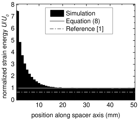
The results have been normalized to the energy contained in a slice of a homogeneously loaded spacer, as described by equation (8) in section II. While the energy stored in the central part of the spacer matches the value predicted by equation (8), excess energy from additional deformations is stored close to the mirror. The penetration depth amounts to roughly 10 mm. The excess energy can be attributed to stress acting non-uniformly on the front face of the spacer as illustrated in Figure 2. The analytic estimate can be reproduced by applying a homogeneous force along the spacer’s front face as expected. The amount of excess energy on the spacer ends depends on the design parameters of the cavity.
The dependence of the strain energy on the length of the cavity is shown in Figure 4 in comparison with the analytic estimates from equation (8) and from num04 .
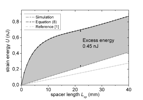
For cavities longer than the penetration depth of the local deformation of roughly 10 mm the simulation data are offset from the analytic estimate by a constant excess energy of approximately 0.45 nJ. Thus, once the elastic strain energy caused by the local deformations at the spacer’s front faces has been determined for a given cavity geometry, the elastic energy of a cavity of a different length can be calculated according to equation (8). As the analytic estimate predicts the energy to be proportional to the effect of the local deformations becomes negligible for long spacers.
The dependence of the strain energy on the spacer diameter is illustrated in Figure 5 in comparison to the dependence of the analytic result (equation (8)) and num04 . All three curves show a decrease of the strain energy with increasing spacer diameter.
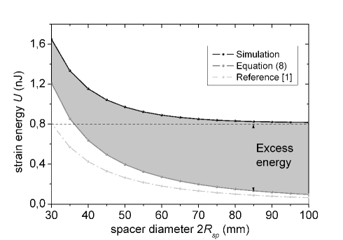
The excess energy increases from 0.45 nJ for a diameter of 32 mm as given in the example before and saturates at 0.8 nJ for a spacer diameter approaching 100 mm. Note that for those diameters the spacer energy is totally dominated by the excess energy close to the mirrors ends.
In summary, equation (8) holds for the central region of the spacer while it fails close to the spacer ends. The impact of the spacer contribution on the total thermal noise budget of the cavity is small for all-ULE cavities, where the dominant part of the noise arises from the mirrors. However, it can be strongly enhanced if the spacer’s mechanical losses exceed the ones for the mirrors (see section III.3) or if nearly confocal cavities with large beam waists on the mirror surface lead to a reduction of the mirror thermal noise. In these cases a careful treatment of the spacer noise in a finite-element analysis is mandatory.
III.2 Support structure
To obtain fractional frequency instabilities below , modern optical cavities employ vibration insensitive mountings web10a ; mil09a ; web08 ; naz06 . In one widely used design for horizontal cavities, the resonators are supported at four positions close to the Airy-points by elastic materials naz06 ; you99 ; web07 ; web08 . As the mechanical quality factor of rubber type material is relatively low the contribution of the support to the thermal noise might not be negligible. To estimate the thermal noise contribution from an elastic support we investigate the geometry depicted in Figure 6.
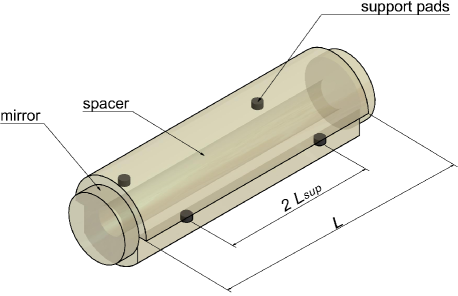
A spacer of length is supported by four rubber supports of thickness , area and shear modulus at the Airy points positioned symmetrically at a distance from the center. As the pads are located far from the spacer’s front faces, local spacer deformations as discussed in section III.1 can be neglected and we can treat the spacer as a homogeneously loaded bar. We again use the fluctuation-dissipation theorem in the form of equation (1) to estimate the thermal noise contribution from the supports. We can estimate the energy stored in the support structure by assuming that the contact surfaces of support and spacer are displaced along the spacer axis direction according to the elastic expansion of the spacer. The support pads are placed at a distance from the center of the spacer. Opposite forces applied on the front faces of the spacer displace each rubber surface by
| (10) |
If we assume the support pads to be fixed to the support structure and have negligible action back on the deformation of the spacer the resulting shear energy for a support pad is given by
| (11) |
In this approximation the shear energy is only affected by the shear strain and the displacement of the boundary is given by the spacer displacement itself. As a result a support with small area , large thickness and small shear modulus will reduce the strain energy and therefore the thermal noise. The thermal noise contribution from four support points is then estimated by
| (12) |
The distance of the support from the center can be estimated for an elastic bar by according to phe66 . Consequently, the displacement noise for the support is proportional to resulting in a fractional displacement noise independent of the cavity length. Therefore, care has to be taken especially for long spacers to avoid excessive influence of the support on the total noise budget.
For a vertical mounting of the cavity at the mid-plane (see e.g. lud07 ; kes10 ) the shear of the support pads acts transversal to the driving force deforming the spacer and the strain energy (equation (11)) is reduced by a factor of .
area 2 mm2 mil09 thickness 0.7 mm mil09 Young’s modulus 0.8 MPa Poisson’s ratio 0.27 shear modulus MPa hof03 loss angle 0.33 gia96 ; hof03
For the horizontal cavity design with the parameters given in tables 3 and 1 we can estimate that the support of 4 viton pads amounts to roughly 1% of the displacement noise m2/Hz created in an ULE spacer. For spacer materials of higher mechanical quality however the ratio can increase drastically and therefore in future cavity designs the importance of the mounting scheme will increase. For a cavity made of silicon for example Young’s modulus in the direction is 188 GPa wor65 and the mechanical loss angle of the material is gui78 , about three orders of magnitude below the one for ULE (see Table 1). Consequently, for a cavity made out of silicon the total thermal noise of the four support pads exceeds the noise of the spacer by a factor of . Cavities of this type of material are currently limited entirely by the coating noise. However once low-loss coatings with sufficient reflectivities bru10 are available this picture might change.
III.3 Mixed material cavities
In present cavities with ULE mirrors the major contribution to the cavity’s thermal noise arises from their mirror substrates. Substrate materials of higher mechanical Q-factor like fused silica (FS) have been used mil09 ; leg10 to reduce this noise contribution. The thermal noise of FS-mirrors is already dominated by the noise of the coating (compare Figure 7). However, fused silica shows a relatively large room temperature CTE of around /K. The large CTE-difference in such a mixed material cavity leads to an unwanted lowering of the zero crossing temperature of the cavity’s CTE in the order of a few 10 K. To compensate for this effect, either special mirror configurations have been applied web10a or additional ULE rings have been optically contacted to the back surfaces of the FS mirrors leg10 .
We use the FEM model discussed above to check whether the additional ULE rings of the latter approach corrupt the low thermal noise of the FS mirrors.
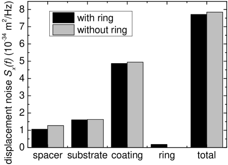
To the cavity model shown in Figure 1 additional 6 mm thick ULE rings with a diameter of 25.4 mm and a central bore of 9 mm have been added. Figure 7 shows the FEM results of the thermal noise contributions of the different cavity components. We find that the additional thermal noise of the ULE ring is much smaller than the noise contribution of the mirror substrate or the mirror coating. The ULE rings enlarge the effective thickness of the mirrors which results in a smaller spacer deformation and therefore in a smaller spacer excess energy. This reduction in the corresponding thermal noise is even bigger than the additional thermal noise contribution of the rings itself and we have the paradoxical situation that a combined material cavity with additional ULE rings show less thermal noise than without these rings.
While for all-ULE cavities the spacer contribution is negligible, in mixed material cavities the ULE spacer starts limiting the performance of the cavity. In general, following the discussion from section II, the noise contribution from the spacer is proportional to and consequently a length can be found where the spacer contribution equals the mirror contribution. This effect is illustrated for a fused silica type substrate in Figure 8.
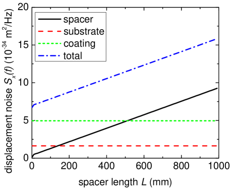
For a cavity with the parameters given in Table 1 this length would correspond to 500 mm.
IV Conclusion
Following Levin’s “direct approach” we have analyzed the fractional length change of state-of-the-art optical cavities driven by Brownian motion thermal noise. While the thermal noise contribution created by the mirror is in good agreement with analytic results, we find discrepancies to the estimates given in num04 for the spacer contribution. We give a revised analytic equation valid for long spacers and find an additional contribution because of additional deformations at the spacer ends close to the mirrors. This excess energy can exceed the energy deposited by linear elastic deformation and can dominate the spacer contribution to the thermal noise for large spacer diameters and also for short spacer lengths.
Another non-negligible source for thermal noise can arise from the support structure of the material. We have given estimate equations for a cavity mounted on soft support pads from below.
Finally we have investigated the thermal noise of mixed-material cavities. We confirm that an additional compensator ring made of ULE (see leg10 ) has no effect on the total cavity thermal noise.
Current cavities are mostly limited by the coating noise. However this may change as low-loss coatings are being developed like microstructured mirrors bru10 or coatings based on monocrystalline AlxGa1-xAs heterostructures col08 . Additional reduction of thermal noise may by achieved by using large mode diameters or higher-order transversal modes mou06 . In these cases the results given in this publication enable further reduction of the thermal noise from the spacer, e.g. using thick mirrors, long cavities and optimized mounting. With these precautions instabilities below seem to be possible.
Acknowledgment
We acknowledge financial support by the Centre for Quantum Engineering and Space-Time Research (QUEST). This work is supported by the European Community s ERA-NET-Plus Programme under Grant Agreement No. 217257, by the ESA and DLR in the project Space Optical Clocks.
References
- (1) K. Numata, A. Kemery, and J. Camp, “Thermal-noise limit in the frequency stabilization of lasers with rigid cavities,” Phys. Rev. Lett. 93, 250602–1–4 (2004).
- (2) T. Rosenband, D. B. Hume, P. O. Schmidt, C. W. Chou, A. Brusch, L. Lorini, W. H. Oskay, R. E. Drullinger, T. M. Fortier, J. E. Stalnaker, S. A. Diddams, W. C. Swann, N. R. Newbury, W. M. Itano, D. J. Wineland, and J. C. Bergquist, “Frequency ratio of Al+ and Hg+ single-ion optical clocks; metrology at the 17th decimal place,” Science 319, 1808–1812 (2008).
- (3) A. D. Ludlow, T. Zelevinsky, G. K. Campbell, S. Blatt, M. M. Boyd, M. H. G. de Miranda, M. J. Martin, J. W. Thomsen, S. M. Foreman, J. Ye, T. M. Fortier, J. E. Stalnaker, S. A. Diddams, Y. L. Coq, Z. W. Barber, N. Poli, N. D. Lemke, K. M. Beck, and C. W. Oates, “Sr lattice clock at fractional uncertainty by remote optical evaluation with a Ca clock,” Science 319, 1805–1808 (2008).
- (4) A. Bartels, S. A. Diddams, C. W. Oates, G. Wilpers, J. C. Bergquist, W. H. Oskay, and L. Hollberg, “Femtosecond-laser-based synthesis of ultrastable microwave signals from optical frequency references,” Opt. Lett. 30, 667–669 (2005).
- (5) J. Millo, M. Abgrall, M. Lours, E. English, H. Jiang, J. Guéna, A. Clairon, S. Bize, Y. L. Coq, G. Santarelli, and M. Tobar, “Ultra-low noise microwave generation with fiber-based optical frequency comb and application to atomic fountain clock,” Opt. Lett. 34, 3707–3709 (2009).
- (6) B. Lipphardt, G. Grosche, U. Sterr, C. Tamm, S. Weyers, and H. Schnatz, “The stability of an optical clock laser transferred to the interrogation oscillator for a Cs fountain,” IEEE Trans. Instrum. Meas. 58, 1258–1262 (2009).
- (7) P. A. Williams, W. C. Swann, and N. R. Newbury, “High-stability transfer of an optical frequency over long fiber-optic links,” J. Opt. Soc. Am. B 25, 1284–1293 (2008).
- (8) H. Jiang, F. Kéfélian, S. Crane, O. Lopez, M. Lours, J. Millo, D. Holleville, P. Lemonde, C. Chardonnet, A. Amy-Klein, and G. Santarelli, “Transfer of an optical frequency over an urban fiber link,” J. Opt. Soc. Am. B 25, 2029–2035 (2008).
- (9) O. Terra, G. Grosche, K. Predehl, R. Holzwarth, T. Legero, U. Sterr, B. Lipphardt, and H. Schnatz, “Phase-coherent comparison of two optical frequency standards over 146 km using a telecommunication fiber link,” Appl. Phys. B 97, 541–551 (2009).
- (10) B. C. Young, F. C. Cruz, W. M. Itano, and J. C. Bergquist, “Visible lasers with subhertz linewidths,” Phys. Rev. Lett. 82, 3799–3802 (1999).
- (11) H. Stoehr, F. Mensing, J. Helmcke, and U. Sterr, “Diode laser with 1 Hz linewidth,” Opt. Lett. 31, 736–738 (2006).
- (12) M. Notcutt, L.-S. Ma, A. D. Ludlow, S. M. Foreman, J. Ye, and J. L. Hall, “Contribution of thermal noise to frequency stability of rigid optical cavity via Hertz-linewidth lasers,” Phys. Rev. A 73, 031804 (2006).
- (13) A. D. Ludlow, X. Huang, M. Notcutt, T. Zanon-Willette, S. M. Foreman, M. M. Boyd, S. Blatt, and J. Ye, “Compact, thermal-noise-limited optical cavity for diode laser stabilization at ,” Opt. Lett. 32, 641–643 (2007).
- (14) S. A. Webster, M. Oxborrow, S. Pugla, J. Millo, and P. Gill, “Thermal-noise-limited optical cavity,” Phys. Rev. A 77, 033847–1–6 (2008).
- (15) P. Dubé, A. Madej, J. Bernard, L. Marmet, and A. Shiner, “A narrow linewidth and frequency-stable probe laser source for the 88Sr+ single ion optical frequency standard,” Appl. Phys. B 95, 43–54 (2009).
- (16) J. Lodewyck, P. G. Westergaard, A. Lecallier, L. Lorini, and P. Lemonde, “Frequency stability of optical lattice clocks,” New Journal of Physics 12, 065026 (2010).
- (17) J. Millo, D. V. Magalhães, C. Mandache, Y. Le Coq, E. M. L. English, P. G. Westergaard, J. Lodewyck, S. Bize, P. Lemonde, and G. Santarelli, “Ultrastable lasers based on vibration insensitive cavities,” Phys. Rev. A 79, 053829 (2009).
- (18) Y. Levin, “Internal thermal noise in the LIGO test masses: A direct approach,” Phys. Rev. D 57, 659–663 (1998).
- (19) T. Legero, T. Kessler, and U. Sterr, “Tuning the thermal expansion properties of optical reference cavities with fused silica mirrors,” J. Opt. Soc. Am. B 27, 914–919 (2010).
- (20) T. Kessler, “Development of an ultrastable monocrystalline silicon resonator for optical clocks,” European Frequency and Time Forum 2010, Noordwijk (2010).
- (21) M. Notcutt, C. T. Taylor, A. G. Mann, and D. G. Blair, “Temperature compensation for cryogenic cavity stabilized lasers,” J. Phys. D: Appl. Phys. 28, 1807–1810 (1995).
- (22) F. Bondu, P. Hello, and J.-Y. Vinet, “Thermal noise in mirrors of interferometric gravitational wave antennas,” Phys. Lett. A 246, 227–236 (1998).
- (23) V. B. Braginsky, M. L. Gorodetsky, and S. P. Vyatchanin, “Thermodynamical fluctuations and photo-thermal shot noise in gravitational wave antennae,” Physics Letters A 264, 1 – 10 (1999).
- (24) Y. T. Liu and K. S. Thorne, “Thermoelastic noise and homogeneous thermal noise in finite sized gravitational-wave test masses,” Phys. Rev. D 62, 122002 (2000).
- (25) V. B. Braginsky and S. P. Vyatchanin, “Thermodynamical fluctuations in optical mirror coatings,” Phys. Lett. A 312, 244–255 (2003).
- (26) M. M. Fejer, S. Rowan, G. Cagnoli, D. R. M. Crooks, A. Gretarsson, G. M. Harry, J. Hough, S. D. Penn, P. H. Sneddon, and S. P. Vyatchanin, “Thermoelastic dissipation in inhomogeneous media: loss measurements and displacement noise in coated test masses for interferometric gravitational wave detectors,” Phys. Rev. D 70, 082003–1–19 (2004).
- (27) M. Evans, S. Ballmer, M. Fejer, P. Fritschel, G. Harry, and G. Ogin, “Thermo-optic noise in coated mirrors for high-precision optical measurements,” Phys. Rev. D 78, 102003–1–10 (2008).
- (28) Y. Levin, “Fluctuation-dissipation theorem for thermo-refractive noise,” Phys. Lett. A 372, 1941–1944 (2008).
- (29) M. L. Gorodetsky, “Thermal noises and noise compensation in high-reflection multilayer coating,” Phys. Lett. A 372, 6813–6822 (2008).
- (30) H. B. Callen and T. A. Welton, “Irreversibility and generalized noise,” Phys. Rev. 83, 34–40 (1951).
- (31) D. W. Allan, “Statistics of atomic frequency standards,” Proc. IEEE 54, 221–230 (1966).
- (32) G. M. Harry, A. M. Gretarsson, P. R. Saulson, S. E. Kittelberger, S. D. Penn, W. J. Startin, S. Rowan, M. M. Fejer, D. R. M. Crooks, G. Cagnoli, J. Hough, and N. Nakagawa, “Thermal noise in interferometric gravitational wave detectors due to dielectric optical coatings,” Class. Quantum Grav. 19, 897–917 (2002).
- (33) K. Yamamoto, “Study of the thermal noise caused by inhomogeneously distributed loss,” Ph.D. thesis, Department of Physics, Graduate school of Science, University of Tokyo (2000).
- (34) Comsol AB, “Comsol Multiphysics Version 4.1,” (2010).
- (35) S. A. Webster and P. Gill, “Low-thermal-noise optical cavity,” in “Proceedings of the 2010 IEEE International Frequency Control Symposium,” (2010), pp. 470–473.
- (36) T. Nazarova, F. Riehle, and U. Sterr, “Vibration-insensitive reference cavity for an ultra-narrow-linewidth laser,” Appl. Phys. B 83, 531–536 (2006).
- (37) S. A. Webster, M. Oxborrow, and P. Gill, “Vibration insensitive optical cavity,” Phys. Rev. A 75, 011801(R)–1–4 (2007).
- (38) F. Phelps, “Airy points of a meter bar,” Am. J. Phys. 34, 419–422 (1966).
- (39) J. J. Wortman and R. A. Evans, “Young’s modulus, shear modulus, and Poisson’s ratio in silicon and germanium,” J. Appl. Phys. 36, 153–156 (1965).
- (40) D. F. McGuigan, C. C. Lam, R. Q. Gram, A. W. Hoffman, D. H. Douglass, and H. W. Gutche, “Measurements of the mechanical Q of single-crystal silicon at low temperatures,” J. Low Temp. Phys. 30, 621–629 (1978).
- (41) F. Brückner, D. Friedrich, T. Clausnitzer, M. Britzger, O. Burmeister, K. Danzmann, E.-B. Kley, A. Tünnermann, and R. Schnabel, “Realization of a monolithic high-reflectivity cavity mirror from a single silicon crystal,” Phys. Rev. Lett. 104, 163903 (2010).
- (42) G. D. Cole, S. Gröblacher, K. Gugler, S. Gigan, and M. Aspelmeyer, “Monocrystalline heterostructures for high-reflectivity high-Q micromechanical resonators in the megahertz regime,” Appl. Phys. Lett. 92, 261108 (2008).
- (43) B. Mours, E. Tournefier, and J.-Y. Vinet, “Thermal noise reduction in interferometric gravitational wave antennas: using high order TEM modes,” Classical Quantum Gravity 23, 5777 5784 (2006).
- (44) D. Hoffman, “Dynamic mechanical signatures of Viton A and plastic bonded explosives based on this polymer,” Polym. Eng. Sci. 43, 139–156 (2003).
- (45) J. Giaime, P. Saha, D. Shoemaker, and L. Sievers, “A passive vibration isolation stack for LIGO: Design, modeling, and testing,” Rev. Sci. Instrum. 67, 208–214 (1996).