Status of the KATRIN experiment with special emphasis on source-related issues
Abstract
The Karlsruhe Tritium Neutrino experiment KATRIN will allow a model independent measurement of the neutrino mass scale with an expected sensitivity of 0.2 eV/c2 (90% C.L.) and so will help to clarify the role of neutrinos in the early universe. KATRIN investigates spectroscopically the electron spectrum from tritium -decay 3H 3He + e- + close to the kinematic endpoint of 18.6 keV with a high resolution electro-static filter of unprecedented energy resolution of E = 0.93 eV designrep . KATRIN will be built at the Tritium Laboratory Karlsruhe on site of the KIT Campus North.
I Introduction
The properties of neutrinos and especially their rest mass play an important role at the intersections of cosmology, particle physics and astroparticle physics. In standard cosmological models, our universe is filled with primordial neutrinos arising from freeze-out in the early universe. These neutrinos are natural candidates for non-baryonic hot dark matter hanne .
A model-independent approach to determine the neutrino mass is the kinematical analysis of electrons from radioactive - decay near the endpoint energy E0 otten . A non-vanishing neutrino mass reduces the electron endpoint energy and distorts the shape of the electron spectrum.
II The KATRIN experiment
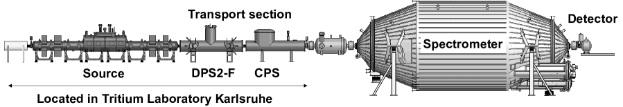
A scheme of the 70 m long KATRIN setup is shown in figure 1. KATRIN uses a strong windowless gaseous tritium source of almost pure molecular tritium (95%) with a throughput of 40 g tritium per day stabilized on 0.1% level. The decay electrons are guided adiabatically from the source through a transport section to the spectrometer system by means of superconducting magnets while at the same time the tritium flow rate to the spectrometers has to be reduced by a factor , since the background rate generated by tritium decay within the spectrometers has to be less than 10-3 counts/s in order to reach the sensitivity KATRIN is aiming for. The transport section consists of a differential pumping section (DPS2-F) and a cryogenic pumping section (CPS). In the DPS2-F the tritium flow will be reduced by differential pumping while in the CPS tritium will be adsorbed on a pre-condensed argon layer prepared inside KATRIN’s beamtube. In addition to the low background an high energy resolution as well as high statistics are a necessity. A tandem spectrometer system is used for energy analysis, followed by a detector-system for counting the transmitted -decay electrons. Both spectrometers are of the MAC-E-Filter (Magnetic Adiabatic Collimation followed by Electrostatic Filter) mace , mace2 type.
The following subsections address the details of some key components related to the source and transport section and their present status.
II.1 Windowless Gaseous Tritium Source
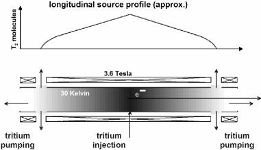
One of the key parameters of KATRIN is the stability of the source on 0.1% level. Figure 2 shows the principle of KATRIN’s Windowless Gaseous Tritium Source (WGTS). At the center of the beamtube molecular tritium gas will be injected continuously. After injection the T2 molecules will diffuse to both ends of the WGTS beam-tube, where most of the tritium will be pumped out continuously by turbomolecular pumps (TMP) in the first stages of the differential pumping section (DPS1), processed and reinjected. The density profile of the gas inside the 10 m long beam-tube has to be kept stable on the 0.1% level. Maintaining the required stable injection rate is provided by the Inner Loop System discussed in the next section. In addition the temperature of the source beamtube has to be stabilized as well. Maintaining these conditions is a very challenging task.
To stabilize the beam tube temperature with a stability of 0.1% at a setpoint of about 30 K, two copper tubes are braced on the source beamtube which directly couple the beamtube to a two phase Neon thermosiphon demo . This cooling concept is currently being tested at the WGTS demonstrator, a partly assembled version of the later WGTS cryostat which houses the later beam-tube and cryogenics but not the superconducting magnets. After finishing the demonstrator tests the WGTS cryostat will be completed in order to be ready for implementation into the KATRIN beam line.
With the first measurements a temperature stabilization in the milli-Kelvin range has been achieved, an improvement of a factor of 10 to 20 with regard to the specification.
II.2 Inner Loop System
In order to keep the pressure profile stable it is necessary to inject the tritium gas with a stability of 0.1%, concerning flow-rate and composition. This challenging task is performed by the Inner Loop System, illustrated in a simplified flow diagram in figure 3. Tritium is being injected from a pressure controlled buffer vessel over a capillary with constant conductivity in the middle of the source beam tube. The gas pumped out by the TMPs gets pumped through a palladium membrane filter (permeator) in a buffer vessel. From there the gas is led over a Laser Raman sampling cell and a regulating valve back into the pressure controlled buffer vessel. At the filter impurities like 3He from tritium decay and tritiated methanes, being generated due to interactions of tritum with the carbon inside the stainless steel walls of the system, are being detached from the gas stream. The amount of gas not recirculated is replaced by tritium from TLK’s Isotope Separation System.
The Inner Loop System has been set up and commissioned successfully. The first test-runs have been performed with a capillary of similar conductance as KATRIN’s injection capillary and source tube loops . Being designed for a stability of 10-3, these test runs showed that the loop system reaches a stability level during 4 week of continuous gas circulation.

II.3 Laser Raman Spectroscopy
Any small change of the tritium gas composition will manifest itself in non-negligible effects on the KATRIN measurements; therefore, precise methods to specifically monitor the gas composition have to be implemented. Laser Raman Spectroscopy is the method of choice for the monitoring of the gas composition because it is a non-invasive and fast in-line measurement technique. Laser Raman spectroscopy allows to monitor all hydrogen isotopologues (T2, DT, D2, HT, HD, H2) simultaneously lara1 . Before entering the injection vessel in the above described Inner Loop system, the gas passes a Laser Raman cell in which the gas is being analyzed. Measurements on flowing non-tritiated lara2 and tritiated lara3 gas samples have been performed. A level of detection of 3 mbar partial pressure in 1 s acquisition time has been achieved lara4 .
II.4 Differential Pumping Section
The DPS2-F represents the last stage of turbomolecular pumping in the transport section. Its reduction of the gas-flow in direction of the spectrometers is of high importance to achieve the 14 orders of flow rate reduction from gas injection point in WGTS to the end of the transport section. At the DPS2-F the gas flow to the spectrometers will be reduced by 4 differential pumping TMPs by about 5 orders of magnitude.
Another item the DPS2-F has to deal with is that in the KATRIN source tube ions and ion clusters are being created. An accumulation of ions inside the beamtube would distort the -spectrum, in addition these ions are not effectively pumped out, since they are confined by the magnetic field in a similar way as the electrons. To prevent this, a dipole system for ion removal as well as two Fourier-transform-ion cyclotron resonance (FTICR) fticr ion traps for ion-concentration monitoring will be installed in the beamtube of the DPS2-F. This instrumentation also increases the gas-flow reduction factor compared to the bare beamtube by reducing the inner beam-tube diameter dps2 . Up to now measurements of the reduction factor with various gases have been performed without instrumentation inside the beamtube. The measured gas-flow reduction factors for this geometry are in good agreement with simulations dps .
III Conclusion
KATRIN has ambitious goals, both in particle physics and in the technical realization of the experimental set-up. Currently the spectrometers, the detector and the DPS2-F cryostat are on site. The first measurements for the temperature stabilization of the source beam tube with the demonstrator, as well as the first gas-flow reduction factor measurements with the DPS2-F have been successful. The Inner Loop system has been successfully commissioned and Laser Raman Spectroscopy for monitoring the gas composition has been successfully implemented. The next major steps to finalize the experiment setup will be finishing the manufacturing of the WGTS cryostat and the delivery of the CPS. After delivery, installation test of all components the experiment will be ready for the first tritium measurements.
Acknowledgements.
The work of the author was supported in part by BMBF (05A08PM1) and DFG SFB Transregio 27 Neutrinos and Beyond .References
- (1) KATRIN Collaboration, KATRIN Design Report 2004, FZKA report 7090
- (2) S. Hannestad, Neutrinos in cosmology, New Journal of Physics, Vol 6, No. 108, 2004 arXiv:hep-ph/0404239v1
- (3) E.W. Otten et al., Neutrino mass limit from tritium -decay, Rep. Prog. Phys 71 (2008) 086201, arXiv:0909.2104
- (4) G. Beamson et al., The collimating and magnifying properties of a superconducting field photoelectron spectrometer, Journal of Physics E: Scientific Instruments 13 (64-66) 1980
- (5) A. Picard et al., A solenoid retarding spectrometer with high resolution and transmissin for keV electrons, Nuclear Instruments and Methods in Physics research Section B Volume 63, Issue 3, 1992, pages 345-358
- (6) M. Sturm, Dissertation, 2010, http://digbib. ubka.uni-karlsruhe.de/volltexte/1000019355
- (7) M. Sturm et al., Monitoring of all hydrogen isotopologues at tritium laboratory Karlsruhe using Raman spectroscopy, Laser Physics 20, 2, 493 (2010)
- (8) R. J. Lewis et al., Dynamic Raman spectroscopy of hydrogen isotopomer mixtures in-line at TILO, Laser Phys. Lett. 5, 7, 522 (2008)
- (9) S. Fischer et al., Monitoring of Tritium purity during Long-Term Circulation in the KATRIN Test Experiment LOOPINO using Laser Raman Spectroscopy, Fusion Science and Technology, Volume 60, Number 3, October 2011, Pages 925-930
- (10) M. Schlösser et al., Design Implications for Laser Raman Measurement Systems for Tritium Sample-Analysis, Accountancy or Process-Control Applications, Fusion Science and Technology, Volume 60, Number 3, October 2011, Pages 976-981
- (11) S. Grohmann et al., Stability analyses of the beam tube cooling in the KATRIN source cryostat, Cryogenics, Volume 49, Issue 8 (2009) 413-420
- (12) M. Ubieto-D az et al., A broad-band FT-ICR Penning trap system for KATRIN, International Journal of Mass Spectrometry, Volume 288, Issues 1-3, November-December 2009, Pages 1-5
- (13) S. Lukic et al., Ion source for tests of ion behavior in the KATRIN beam line, Rev. Sci. Instrum. 82 (2011), issue 1 (Jan 2011)
- (14) S. Lukic et al., Measurement of the gas-flow reduction factor of the KATRIN DPS2-F differential pumping section, arXiv:1107.0220v1