Saying Hello World with Henshin-
A Solution to the TTC 2011 Instructive Case
Abstract
This paper gives an overview of the Henshin solution to the Hello World case study of the Transformation Tool Contest 2011, intended to show basic language concepts and constructs.
1 Introduction
In the modeling community, the Eclipse Modeling Framework (EMF) [7] has evolved to a well-known and widely used technology. It is obviously promising to provide model transformation support for EMF. With Henshin [2, 4], a declarative transformation language and tool environment for EMF models is available. Particularly, EMF models are transformed directly, called in-place, without the need of back and forth conversions and copies. Henshin supports the transformation of EMF models by generated code as well as those created dynamically. Its transformation concepts base on the well-founded theory of algebraic graph transformation with pattern-based rules as main artifacts, extended by nestable application conditions and attribute computation. Moreover, the Henshin transformation language allows to structure rules by means of nestable transformation units with well-defined operational semantics. Additionally, a state space generator supports reasoning by model checking which is, however, not further investigated here. The export of rules to AGG [8] is possible as well, where analysis concerning conflicts and dependencies as well as termination may take place. Graphical editors support the definition of Henshin model transformations in several fashions.
2 Henshin Transformation in a Nutshell
The Henshin transformation meta-model is an EMF model itself. Its main artifacts are rules essentially consisting of two graphs, a left-hand side (LHS) and a right-hand side (RHS), specifying model patterns on abstract syntax level. The LHS describes the pattern to be found while the RHS describes the resulting pattern. Nodes and edges occurring in the LHS or RHS only, are deleted or created, respectively. Node mappings between LHS and RHS declare identity, i.e., related nodes and edges are preserved. Rules may also be equipped with positive and negative application conditions (PACs and NACs) being graph patterns again which confine the match furthermore. Their true power emerges in combination with logical formulas (AND, OR, NOT) and with nesting even allowing to define conditions over conditions. Moreover, in the context of rules attribute conditions can be defined whose expressions are evaluated by a JavaScript engine at runtime.
The order of rule applications can be controlled by transformation units, short units, providing a well-defined operational semantics. Units may contain other units including rules which can be considered as atomic units corresponding to their single application. Henshin offers a predefined set of units: IndependentUnits provide a non-deterministic unit choice, PriorityUnits specify priorities in which contained units are chosen to be applied, a counted application is provided by the CountedUnit at which a count value of -1 specifies a loop, i.e., “as often as possible”, SequentialUnits apply rules in a sequential order and perform a rollback if any of its rules cannot be applied, and ConditionalUnits allow to specify an if condition with a corresponding then and else part. Last but not least, AmalgamationUnits are special units expressing forall-operations on recurring model patterns. Here, a kernel rule is applied once with a number of multi rules being applied as often as possible taking the match of the kernel rule into account.
The object flow can be specified along the control flow using parameters and parameter mappings. They may pass objects and values from one unit to another one in order to pre-define (partial) matches.
Currently three different editors provide three different views on Henshin transformation models. A tree-based editor provides a very low-level view on the internal model structure, while two other editors offer a more sophisticated graph-like visualization. One visual editor, in the following called complex editor, shows LHS, RHS and application conditions in separate views and is particularly suitable for complex transformation systems with arbitrary control and object flows. In contrast, the visual integrated-rule editor shows rules in an integrated manner in a single view utilizing stereotypes to denote creation, deletion and preservation. This editor is more suitable for simple rules. Note, the figures in this paper show one or the other visual representation according to its appropriateness in each individual case.
The application of rules and transformation units on arbitrary models can be triggered by a wizard on the one hand. On the other hand, Henshin has been designed in a modular way with an independent transformation engine such that it can be freely integrated into any Java project relying on EMF models. Flexible properties allow to switch between injective (default) and non-injective matching. Dedicated classes, RuleApplication and UnitApplication, provide appropriate methods to select and apply rules and transformation units, respectively.
3 Case Study Tasks Solved by Henshin
In the following a representative subset of the complete solution of the Hello World challenge [6] is presented while a full listing is given in Appendix A. Each transformation is triggered via Java source code. In order to display/persist a transformation’s outcome, appropriate rules or units contain a parameter, e.g., result or counter, which is fetched on code level (see Appendix B). Furthermore, in some cases we exploit a Henshin self-contained helper structure called trace model in order to keep track of the transformation process. This model consists of a class Trace which might be connected to any EMF object by two references, source and target.
Task 1: Hello World!
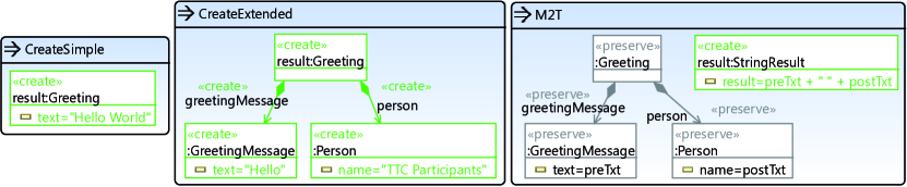
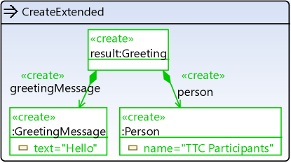
Figure 1 shows the solutions for each of the tree subtasks of the first Hello World! task by means of the integrated-rule editor. Each rule is presented as rounded rectangle with its name at the top and its graph structure contained. Stereotypes denote related nodes and edges to be created, deleted or preserved. Note, in the editor undefined stereotypes default to preserve. However, it is conceivable to omit that stereotype at all in the future.
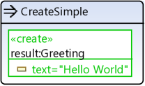
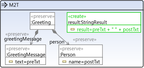
In the left of Fig. 1, rule CreateSimple consists of a node of type Greeting to be created which is assigned to the parameter result. The value of its attribute text is also set to the string "Hello World". Rule CreatedExtended, located in the center of Fig. 1, creates a more complex greetings structure by introducing a number of nodes and edges. The model-to-text transformation subtask is represented by the rule M2T which preserves a given greetings structure while creating a new :StringResult object. In addition, two parameters, preTxt and postTxt, are utilized to fetch the corresponding attribute values of the matched objects :GreetingMessage and :Person in order to participate in the attribute computation for the :StringResult object.
Task 2: Count Matches.
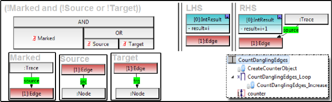
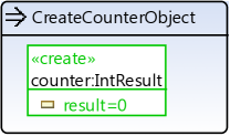
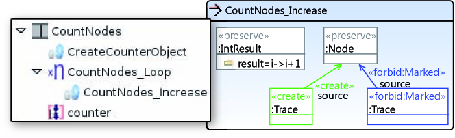
All related subtasks are implemented by structurally similar sequential units while one, CountDanglingEdges, is exemplarily illustrated in Fig. 2 by means of the complex editor. Actually, this figure is a compositions of different views of the complex editor in favor of space savings. The control flow is shown in the lower right where at first rule CreateCounterObject is applied. It creates an initial counter:IntResult object used for counting and used as return value with the help of parameter counter. Note that the same rule is reused by all subtasks. Afterwards, contained in a counted unit CountDanglingEdges_Loop, rule CountDanglingEdges_Increase is applied as often as possible performing the actual counting. Its LHS, RHS (upper right) and NACs (left) are shown in Fig. 2 as well. Identical nodes are indicated by numbers in brackets. This rule matches the :IntResult object and an :Edge object which has not been marked by a :Trace object yet and which has no source or no target, including not having either. Each rule application increases the value of the attribute result by one and marks the edge as being visited by creating and connecting a :Trace object.
Task 3: Reverse Edges.
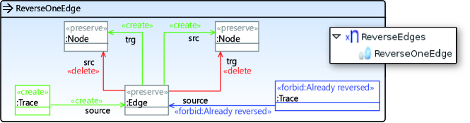
This task is solved by applying the rule ReverseOneEdge (cf. Fig. 3) in a loop as often as possible. :Edge and :Node objects are preserved during the transformation while two references are created and two others are deleted. In addition, a :Trace object is created as marker in combination with the NAC “Already reversed” which forbids such a marker to exist in the given context.
Another solution would have been using an amalgamation unit. In this case, the kernel rule would be empty. The multi rule would be similar to the rule ReverseOneEdge but without the NAC and the trace objects, since a single application of an amalgamation unit matches each multi rule as often as possible and performs all those transformations in parallel. See Task 5 for more details on amalgamation units.

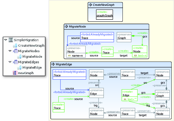
Task 4: Simple Migration.
The solution for this task uses techniques already known. At first the rule CreateNewGraph creates a new Graph object as initial root object. Afterwards, one rule (MigrateNode) migrating a single node is applied in a loop and subsequently one rule (MigrateEdge) migrating an edge is applied in a loop too. Again, :Trace objects mark those elements already translated.
There are a number of alternative ways to realize this task. For example, one could use an amalgamation unit creating a :Graph object in the kernel rule and performing the node migration in a multi rule without the need of trace objects. Another amalgamation unit could realize the migration of edges. Then, the whole migration would require the sequential application of both units.
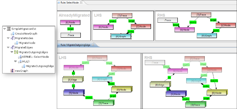
The solution for the extended task is actually realized with the help of an amalgamation unit. We skip this here and rather refer to the following task using this special kind of unit as well.
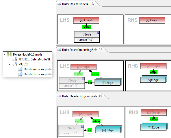
Task 5: Delete Node and its Incident Edges.
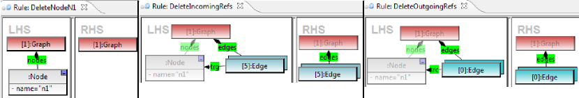
Both deletion subtasks have been solved using amalgamation units. Figure 4 shows all parts of the amalgamation unit DeleteNodeN1Simple realizing the core task. The left rule, DeleteNodeN1, serves as kernel rule and matches a :Graph object and a connected :Node object named “n1”. Its RHS points out that the node is to be deleted. The rules DeleteIncomingRef and DeleteOutgoingRef serve as multi rules. Their names indicate already, that they delete an incoming and an outgoing reference, respectively. Each multi rule is defined in the context of its kernel rule denoted by the parts grayed out in the LHS and RHS of the multi rules, while the parts belonging to the multi rule are illustrated by double rectangles. An application of the amalgamation unit leads to a single match of the kernel rule and all possible matches of the multi rules taking the match of the kernel rule into account. For further information on amalgamation units please refer to [3].
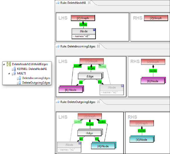
The extended task is realized in a similar way and thus not shown here (see Appendix).
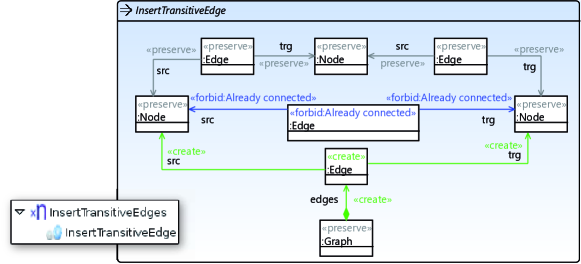
Task 6: Insert Transitive Edges.
The last task is solved by the rule InsertTransitiveEdge applied in a loop to create a single transitive edge for an already existing connection between three Node objects. This is quite analogous to what has been explained above and therefore not presented in detail here.
4 Conclusion
This paper presents the solution of the Hello World challenge [6] implemented by Henshin. All tasks including all optional tasks are solved. The implementation is made available under SHARE [5].
The solution is particularly characterized by a visual transformation language, pattern-based rules and the capability of defining control and object flows. Three different graphical editors support the creation and editing of Henshin transformation systems, each one with its assets and drawbacks. However, each editor provides a visualization more or less close to the underlying transformation model. For example, the creation of more than two application conditions leads to quite some nesting due to binary formulas as shown in Fig. 2. Moreover, control and object flows are often not easy to grasp. To overcome these issues a more adequate representation is desirable. The question arises whether an integrated visualization of rules and control flow (and object flow) or a separate visualization is more appropriate. Whatever decision will be made, the current major shortcomings of Henshin, understandability and conciseness, need to be addressed in further developments. The application of each transformation is currently triggered by dedicated source code, although a wizard is available as well. However, transformation engine configurations, e.g., switch to non-injective matching, require the use of code yet. Besides the scope of solutions for this task, the performance of Henshin behaves quite well. Additional features to be possibly integrated are attribute computations using OCL expressions, path expressions, and untyped nodes and edges representing elements of arbitrary type improving the understanding of rules.
References
- [1]
- [2] T. Arendt, E. Biermann, S. Jurack, C. Krause & G. Taentzer (2010): Henshin: Advanced Concepts and Tools for In-Place EMF Model Transformation. In: Proc. of 13th Int. Conference on Model Driven Engineering Languages and Systems (MoDELS 2010), LNCS, Springer, pp. 121–135, 10.1007/978-3-642-16145-2_9.
- [3] Enrico Biermann, Claudia Ermel & Gabriele Taentzer (2010): Lifting Parallel Graph Transformation Concepts to Model Transformation based on the Eclipse Modeling Framework. ECEASST 26.
- [4] Henshin (2010): http://www.eclipse.org/modeling/emft/henshin.
- [5] Stefan Jurack & Johannes Tietje (2011): SHARE demo related to the paper Saying Hello World with Henshin - A Solution to the TTC 2011 Instructive Case. http://is.tm.tue.nl/staff/pvgorp/share/?page=ConfigureNewSession&vdi=Ubuntu_10.04_TTC11_Henshin_v2.vdi.
- [6] Steffen Mazanek (2011): Hello World! An Instructive Case for the Transformation Tool Contest. In Pieter Van Gorp, Steffen Mazanek & Louis Rose, editors: TTC 2011: Fifth Transformation Tool Contest, Zürich, Switzerland, June 29-30 2011, EPTCS.
- [7] Dave Steinberg, Frank Budinsky, Marcelo Paternostro & Ed Merks (2009): EMF Eclipse Modeling Framework (Second Edition). Addison-Wesley.
- [8] TFS-Group, TU Berlin (2009): AGG. http://tfs.cs.tu-berlin.de/agg.
Appendix A All Solutions
In the following the solutions to all tasks are given. If appropriate, rules are shown using the integrated-rule editor manually composed with an overview of belonging units. More complex rules are rather given by means of the complex-rule editor showing LHS, RHS and application conditions separately.
A.1 Task 1
-
1.
Constant transformation.
-
2.
Constant transformation that creates a model with references.
-
3.
Model-to-text transformation.
A.2 Task 2
Model query that counts the number of …
-
1.
nodes in a graph.
-
2.
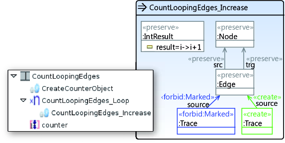
looping edges.
-
3.
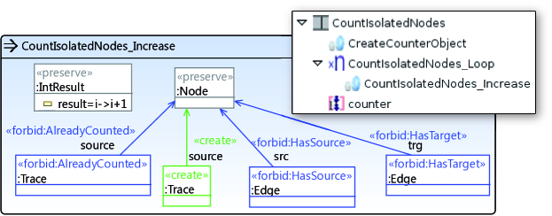
isolated nodes.
-
4.
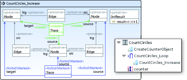
matches of a circle consisting of three nodes.
-
5.
dangling edges.
Each task is solved utilizing a sequential unit containing the rule CreateCounterObject at first and subsequently containing a counted unit with another rule contained. While all solutions to task 2 reuse the same rule CreateCounterObject, the actual counting is performed in the rule contained in the respective counted unit. The counted units have a count value of -1 and thus force the contained rule to be applied in a loop, i.e., as often as possible.

A.3 Task 3
-
1.
Reversing all edges.
The solution to this task is characterized by a counted unit with count=-1 applying rule ReverseOneEdge in a loop, i.e., as often as possible.
A.4 Task 4
-
1.
Simple migration of a graph conforming to one metamodel (graph1) to a graph conforming to a second metamodel (graph2).
-
2.
Topology-changing migration of a graph conforming to one metamodel (graph1) to a graph conforming to a second metamodel (graph3).
A.5 Task 5
-
1.
Deletion of a node with name “n1”.
-
2.
Deletion of a node with name “n1” and all its incident edges.
Each subtask is solved by applying a single amalgamation unit. Note, that the same rule DeleteNodeN1 is reused by both amalgamation units shown below.
A.6 Task 6
The solution to this task turned out to be quite simple: A single rule needs to be called in a loop only.
Appendix B Java Code of the Transformation Application
This section shows the code to trigger the applications of all transformations. Each task is represented by a class containing related code. Note that the classes contain some redundant code in order to allow the reader to concentrate on certain parts without hiding functionality by inheritance and call hierarchies.