A Multi-Path Interferometer on an Atom Chip
Abstract
Cold-atom interferometry is a powerful tool for high-precision measurements of the quantum properties of atoms, many-body interactions and gravity. Further enhancement of sensitivity and reduction of complexity of these devices are crucial conditions for success of their applications. Here we introduce a multi-path interferometric scheme that offers advances in both these aspects. It uses coherent coupling between Bose-Einstein condensates in different Zeeman states to generate an interferometric signal with sharp fringes. We realise such an interferometer as a compact easy-to-use atom-chip device and thus provide an alternative method for measurement of the light-atom and surface-atom interactions.
pacs:
37.25.+k, 67.85.FgThe first demonstration of coherence of a Bose-Einstein condensate (BEC) KetterleSci97 has led to dramatic advancements in atom interferometry. Long coherence times and the localization in phase space of cold-atom clouds and in particular of BECs enable high precision interferometric measurements of the internal properties of atoms, many-body effects and gravity CroninRMP09 . Some notable examples are the determination of spin squeezing OberthalerNat10 ; RiedelNat10 , fine structure constant GuptaPRL02 , density correlations HarberPRA02 , local gravitational acceleration PetersMetro01 , Newtonian gravitational constant FixlerSci07 and rotation rate GustavsonPRL97 .
In the classical limit the best achieved sensitivity of a conventional 2-path interferometer is determined by the shot noise and hence scales as with the number of atoms . This is known as the standard quantum limit (SQL). An improvement in sensitivity beyond the SQL can be achieved by entangling the input and performing a collective non-local measurement at the output. The best possible outcome in a lossless system is the sensitivity of , known as the Heisenberg limit GiovannettiSci04 . An advancement in this direction has recently been demonstrated by employing nonlinear atom-atom interactions to produce the entanglement and therefore reduce the phase-measurement error of a Ramsey interferometer below the SQL OberthalerNat10 . An alternative way to improve the interferometer sensitivity is to increase the fringe slope by increasing the number of paths M as in WeihsOL96 ; WeitzPRL96 . It is paid by a decrease in the average number of atoms per path and hence by a greater susceptibility to noise. If the scaling of slope with M exceeds scaling of the shot noise, the sensitivity improves with the number of paths. Multi-path interferometry can be also seen as a fringe narrowing mechanism that increases measurement resolution WeitzPRL96 ; MitchellNat04 .
Several multi-path matter-wave interferometers have been proposed, the first being an atom-beam interferometer based on the optical pumping between Zeeman states WeitzPRL96 . Multi-path interferometry with cold atoms has been based on the property of an optical lattice to impair a controllable recoil momentum on atoms as in KasevichSci98 ; FattoriPRL08 ; ChuPRL08 ; NaegerlNJP10 ; GuptaPRL02 . While they offer numerous advantages such as a large number of paths, easy control of the relative phase accumulation rate and compatibility with techniques for control of atom-atom interactions, these interferometers crucially depend on alignment, high-resolution imaging and require a sophisticated technology to make them compact and eventually portable.
Here we present a multi-path cold-atom interferometer with distinct narrow fringes that is simple to use and fully merged with an atom chip. The sharpness of the interferometric fringes is due to the interference of atoms at different Zeeman levels populated by high-frequency Rabi pulses. A nearly perfect coherence of this transfer yields a pure output signal without background. The interferometer can be used to measure parameters of state-dependent interactions of atoms with external fields, whereby the simultaneous measurement of multiple fringes at the output allows for application of multi-parameter sensing schemes.
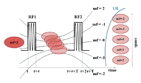
The essential components of the proposed scheme are shown in Fig. 1. The initial state is prepared by condensing atoms in a low field seeking ground state, here . Coherent transfer of the atoms to other Zeeman states of the same hyperfine state is realised by application of a resonant RF pulse. The interferometer is closed by remixing these states by the second RF pulse after a controllable time delay as in MinardiPRL01 . The second pulse maps the relative phases accumulated between different states during the delay into a population distribution at the output of the interferometer. The relative phases between the states are accumulated due to the presence of the trapping magnetic field B. In this field Zeeman states experience different potentials given by where and are respectively the spin and Landè numbers and is the Bohr magneton. Therefore, their relative phases evolve with the frequencies equal to the multiples of the energy separation between the adjacent levels , yielding the interference signals rich in harmonics. The harmonics cause the fringe width to decrease with the number of states, which is the basic characteristic of a multi-path interferometer. If an external signal is applied during the delay between the pulses, it will contribute to the relative phases accumulated between the states causing a shift in the fringe positions at the output. Since the interferometric paths are not spatially separated, the interferometer can be used to measure external fields whose interactions with atoms are state-sensitive. Finally, in order to determine the population of each output state, these states are spatially separated by application of the Stern-Gerlach method followed by the free-fall expansion and then imaged.
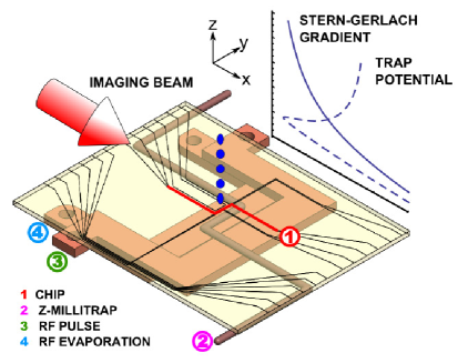
Our interferometric setup was designed to be compact, fast and easy to use. It comprises three essential parts: cooling apparatus, RF-pulse source and detection system. A 87Rb BEC was realised on an atom chip equipped with micrometer wires Vienna and mounted on a holder with additional millimeter U- and Z-wires as shown in Fig. 2. The condensate had 3x10⁴ atoms and the critical temperature of 0.5K and was formed at 200m from the chip surface. It was kept in the cylindrically symmetric z-wire trap with axial and transversal frequencies of 46Hz and 950Hz respectively during the whole interferometric sequence. For each measurement a new BEC was created.
The RF magnetic field was supplied by a waveform generator connected to a U-wire in the chip holder. The pulse frequency matched the separation of the Zeeman sublevels in the magnetic trap. The pulse duration was short enough to ensure that the pulse bandwidth covered the 10KHz energy spread of atoms in the BEC. We note that the RF pulses were not locked in phase, but were phase locked to their respective trigger signals as shown by the waveforms in Fig.1.
The distribution of atoms across the Zeeman states was detected by a 7.5X-magnifying absorption imaging system with the imaging beam set to the transition and a high-resolution camera. Prior to the imaging the Zeeman states were spatially separated by the Stern-Gerlach method using a chip z-wire gradient. The population of each state was normalized to the total atom number making the interferometer independent of small fluctuations in the condensate atom number.
The interferometer is well described by the transfer matrix that acts on a vector of the complex amplitudes of states and is given by the product , where matrix describes the M-level Rabi coupling and matrix the phase evolution of the states. These two matrices are found as solutions of time-dependent Schrödinger equations with the respective Hamiltonians , ShorePRA77 , and , where is the Rabi frequency and the Kronecker symbol. The R matrix elements are calculated by the technique proposed in FujiiJMS08 .
The interferometer output has a form of a finite Fourier series whose terms correspond to the multiples of the energy separation between adjacent Zeeman states in a magnetic field. An increase in the number of paths M leads to an increase in the number and order of the harmonics and hence to sharpening of the interferometric fringes. We note that the transfer function is that of a Fabry-Perot interferometer with a limited number of passes. Moreover, the tridiagonal Rabi transfer matrix is analog to that of an optical lattice TrombettoniPRL01 and an optical waveguide array Yariv . We note that for a number of states larger than 3 the eigenfrequencies of the Hamiltonian are incommensurate to each other making it impossible to define a single pulse capable of creating an arbitrary population distribution. One is therefore limited to optimizing the pulse area for the best possible performance.
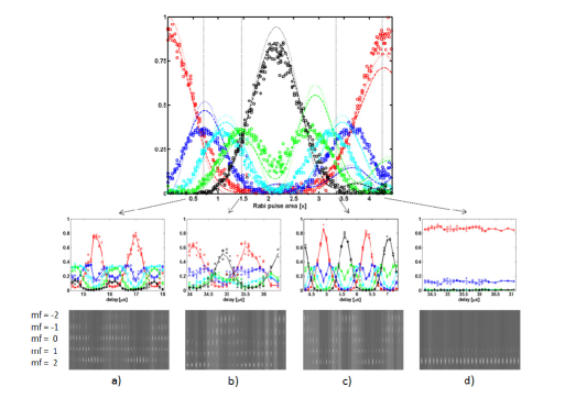
An efficient use of the multiple Zeeman levels depends on the availability of atoms in these levels between the two RF pulses and therefore on the population transfer effected by the first Rabi pulse. The role of the Rabi pulses is analogous to the role of beam splitters in a Mach-Zehnder interferometer. However, here we can control the splitting by varying the pulse parameters, the feature not easily achievable in standard optical setups. The dependence of the interferometer signal on the Rabi pulse area can be understood from Fig. 3. The upper graph shows the measured and calculated population transfers between all five Zeeman states by a single Rabi pulse. Lower graphs show characteristic output signals of the interferometer and the raw absorption images from which these signals are derived. They correspond to the Rabi pulse areas marked by the dashed lines. The Rabi pulse that populates only the highest or the lowest Zeeman states (with around , or ) yields interferometric fringes with low visibility visibility that approaches zero in the extreme case of the complete population cycle, Fig. 3d). Well defined narrow interferometric fringes with enhanced sensitivity can be generated by the pulses that populate most Zeeman states as then most harmonics allowed by the system contribute to the output signal, see plots a)-c) in Fig. 3. The observed control of the fringe sensitivity achieved by varying the Rabi pulse area is a time analog of the control of interferometer output by a variable beam splitter.
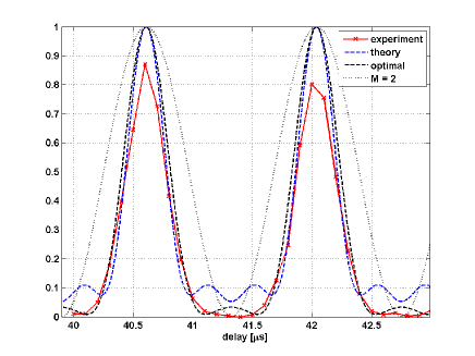
We further used this feature to optimise the output of the interferometer. The sharpest fringes with no side lobes are produced by the Rabi pulses with the area of . Curiously, the realised interferometer outperforms the theoretically predicted as its signal is free from the background observed in the simulation result in Fig. 4. Instead, the measured approaches the optimal theoretical signal of the 5-path interferometer also shown in Fig. 4. We attribute this discrepancy to the simplifications of the model as well as to the experimental error. To evaluate the interferometer performance, we compared the measured fringe slope with that of the ideal 2-path interferometer. The optimal fringe slope of our interferometer is rad-1 and is larger than the 0.5 rad-1 slope of the 2-path interferometer. The improvement is further confirmed by the 1.75 times fringe narrowing. Therefore, we have shown that for an appropriate splitting of states, multiple paths interfere constructively, which results in increase in the interferometer resolution beyond that of an ideal 2-path interferometer.
However, we have not improved the sensitivity in the shot noise limit. This is due to the slow increase in the fringe slope for small M with respect to scaling of noise. For M=5 the ideal slope of rad-1 allows for the realisation and detection of an improvement only if the measurement error is below 3%. Such precision was not reachable in our measurements. A more favourable scaling could be achieved by allowing side lobes and aiming for fringe densification, in analogy with the multi-photon states in quantum optics MitchellNat04 ; WalmsleyNatPhot09 .
A remarkable feature of our interferometer is that the enhancement of resolution is achieved without reduction in visibility. Indeed, the complete transfer of atoms from to and vice versa confirms the coherence of the transfer and renders the fringe visibility of 1 within the 5% experimental error. By the construction of the output signal, the high visibility is a necessary but not sufficient condition for good performance of the interferometer. For instance, the visibility of the fringe in Fig. 3a) is high but its sensitivity is low. The maximum visibility is maintained for the delays between the pulses of up to 50s. For longer delays it decays exponentially with the half-maximum time decay constant of 100s.
Applications of the proposed interferometer are based on different responses of the Zeeman states to an external field. Due to the simultaneous measurement of multiple state populations, the interferometer can be used in two basic measurement configurations: absolute measurement in which the signal is defined as a shift of fringes belonging to a chosen state, and differential measurement in which the signal is defined as the difference in shifts of fringes belonging to different states. An obvious application of the former is in a magnetometer in which the magnetic field magnitude directly maps into the periodicity of the fringes. Other applications are in the measurement of parameters of light-atom interactions, for example the relative atomic polarisability, and of light signals.
A potential disadvantage of the proposed sensor is its cross-sensitivity to the magnetic field. This problem can be resolved by using the differential measurement. In a magnetic field with a changing magnitude all fringes experience the same shift that cancels out in the differential signal. The remaining shift contains only the desired information on the state-dependent interaction of atoms with the external field. The elimination of the cross-sensitivity is paid by a decrease in sensitivity and is thus more efficient for a higher number of paths and well defined fringes. We note that a strong interaction can distort the fringes making the readout of the signals difficult. However, this does not have severe consequences as it limits the application of the interferometer exactly to the regime in which it performs best - the small-signal regime in which the high sensitivity is required.
Finally, we observe that the simultaneous measurement of five output signals enables the application of our interferometer as a multi-parameter sensor. The multi-parameter sensing scheme is based on the difference in sensitivity of Zeeman states to the same signal and simultaneous sensitivity of each state to multiple signals. This concept is well known in photonics where it is employed in interrogation schemes with fibre gratings TatamMST03 , but it has not been used in cold-atom based sensors before.
The integration of the interferometer with an atom chip offers several technical advantages. The small wires allow for fast switching of the magnetic fields thereby shortening the experimental cycle several times with respect to the free-space setups. This is of particular importance for the time-domain interferometers in which the signal is constructed as a series of measurements at different time delays. The proximity of the condensate to the chip wires enables large field gradients that facilitate imaging. The chip interferometer is robust and easy to use and as such is a good candidate for future portable cold-atom sensors. Finally, the advantage that applies equally to the non-chip setups is that the interferometer does not use light signals and therefore does not suffer from the instabilities related to the optical alignment.
To conclude, we have demonstrated a compact time-domain multi-path interferometer on an atom chip whose sensitivity can be controlled by an RF pulse acting as a variable beam splitter. In the optimal configuration it has the resolution superior to that of an ideal two-path interferometer. The simultaneous measurement of multiple signals at the output enables a range of advanced sensing applications in atomic physics and optics, while the integration of interferometer with the chip puts it into consideration for future portable cold-atom based measurement apparatuses. The presented multi-path interferometric scheme can be applied to other atomic species and any BEC setup, and is compatible with the quantum state preparation. Moreover, the analogies of the couplers used here with the optical lattices and coupled optical waveguide arrays indicate the universality of the proposed scheme.
The authors wish to thank M. Inguscio for the continuous support and many useful discussions. We wish to acknowledge the help of L. Consolino and S. Bartalini in the construction of the atom chip setup and useful discussions with C. Fort, M. Fattori and G. Roati. We acknowledge the financial support of the Future and Emerging Technologies (FET) programme within the Seventh Framework Programme for Research of the European Commission, under FET-Open grants MALICIA (265522) and CHIMONO (216774). J.P. acknowledges support of the Ministry of Science of Serbia (Project III 45010). F.S.C. acknowledges support of MIUR (Project HYTEQ).
References
- [1] M. R. Andrews, C. G. Townsend, H.-J. Miesner, D. S. Durfee, D. M. Kurn, and W. Ketterle, Science 275, 637 (1997).
- [2] A. D. Cronin, J. Schmiedmayer, and D. Pritchard, Rev. Mod Phys. 81, 1051 (2009).
- [3] C. Gross, T. Zibold, E. Nicklas, J. Estève, and M. Oberthaler, Nature 464, 1165 (2010).
- [4] M. F. Riedel, P. Böhi, Y. Li, T. W. Hänsch, A. Sinatra, and P. Treutlein, Nature 464, 1170 (2010).
- [5] S. Gupta, K. Dieckmann, Z. Hadzibabic, and D. E. Pritchard, Phys. Rev. Lett. 89, 140401 (2002).
- [6] D. M. Harber, H. J. Lewandowski, J. M. McGuirk, and E. A. Cornell, Phys. Rev. A 66, 053616 (2002).
- [7] A. Peters, K. Y. Chung, and S. Chu. Metrologia 38, 25 (2001).
- [8] J. B. Fixler, G. T. Foster, and J. M. McGuirk, and M. A. Kasevich, Science 315, 74 (2007).
- [9] T. Gustavson, P. Bouyer, and M. Kasevich, Phys. Rev. Lett. 78, 2046 (1997).
- [10] V. Giovannetti, S. Lloyd, and L. Maccone. Science 306, 1330 (2004).
- [11] G. Weihs, M. Reck, H. Weinfurter, and A. Zeilinger, Opt. Lett. 21, 302 (1996).
- [12] M. Weitz, T. Heupel, and T. W. Hänsch. Phys. Rev. Lett. 77, 2356 (1996).
- [13] Visibility is defined as where and are the minimal and maximal output signal amplitudes, as in reference [18].
- [14] M. W. Mitchell, J. S. Lundeen, and A. M. Steinberg, Nature 429 161 (2004).
- [15] B. P. Anderson and M. A. Kasevich, Science 282, 1686 (1998).
- [16] M. Fattori, C. D’Errico, G. Roati, M. Zaccanti, M. Jona-Lasinio, M. Modugno, M. Inguscio, and G. Modugno, Phys. Rev. Lett. 100, 080405 (2008).
- [17] H. Müller, S.-W. Chiow, Q. Long, S. Herrmann, and S. Chu, Phys. Rev. Lett. 100, 180405 (2008).
- [18] M. Gustavsson, E. Haller, M. J. Mark, J. G. Danzl, R. Hart, A. J. Daley, H.-C. Nägerl, New J. Phys. 12, 065029 (2010).
- [19] F. Minardi, C. Fort, P. Maddaloni, M Modugno, and M. Inguscio, Phys. Rev. Lett. 87, 170401 (2001).
- [20] The chip was supplied by the Atom Institute of the University of Vienna through CHIMONO collaboration.
- [21] B. W. Shore and J. Ackerhalt, Phys. Rev. A 15, 1640 (1977).
- [22] K. Fujii, J. Math. Sci. 153, 57 (2008).
- [23] A. Trombettoni and A. Smerzi, Phys. Rev. Lett. 86, 2353 (2001).
- [24] A. Yariv, Optical Electronics in Modern Communications, 5th Ed. (Oxford Univeristy Press, New York, 1997).
- [25] K. Banaszek, R. Demkowicz-Dobrzański, and I. A. Walmsley, Nature Photonics 3, 673 (2009).
- [26] S. W. James and R. P. Tatam, Meas. Sci. Techol. 14, R49 (2003).