Ultrafast all-optical switching by single photons
An outstanding goal in quantum optics is the realization of fast optical non-linearities at the single-photon level. Such non-linearities would allow for the realization of optical devices with new functionalities such as a single-photon switch/transistor Chang:NatPhys07 ; Hwang:Nature09 or a controlled-phase gate Turchette:PRL95 , which could form the basis of future quantum optical technologies Obrien:NatPhot09 . While non-linear optics effects at the single-emitter level have been demonstrated in different systems, including atoms coupled to Fabry-Perot or toroidal micro-cavities Turchette:PRL95 ; Schuster:NatPhys08 ; Dayan:Science08 , super-conducting qubits in strip-line resonators Fink:Nature08 ; Deppe:NatPhys08 ; Bishop:NatPhys09 or quantum dots (QDs) in nano-cavities Hennessy:Nature07 ; Srinivasan:Nature07 ; Fushman:Science08 ; Kasprzak:NatMat10 , none of these experiments so far has demonstrated single-photon switching on ultrafast timescales. Here, we demonstrate that in a strongly coupled QD-cavity system the presence of a single photon on one of the fundamental polariton transitions can turn on light scattering on a transition from the first to the second Jaynes-Cummings manifold with a switching time of 20 ps Faraon:NatPhys08 . As an additional device application, we use this non-linearity to implement a single-photon pulse-correlator. Our QD-cavity system could form the building-block of future high-bandwidth photonic networks operating in the quantum regime Faraon:APL07 ; Brossard:APL10 ; Bose:OptExp11 .
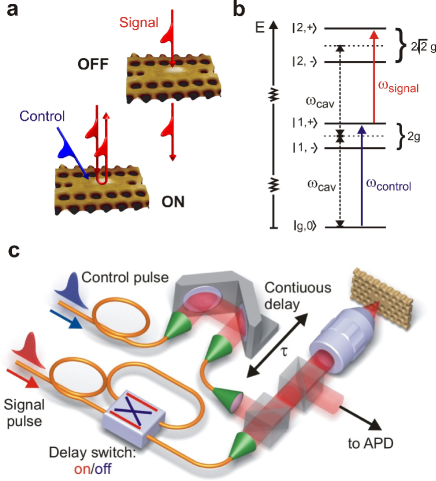
A single-photon switch is a device where a single optical gate (or control) photon controls the propagation (or scattering) of incident signal photons through non-linear optical interactions Chang:NatPhys07 , as illustrated in Figure 1a. The requisite large photon-photon interactions are provided by the basic system of cavity quantum electrodynamics (QED) Mabuchi:Science02 , namely that of a single quantum emitter strongly coupled to a single cavity mode: Figure 1b displays the first two rungs of the corresponding energy diagram, the so-called Jaynes-Cummings ladder. The anharmonicity of the Jaynes-Cummings ladder with the resulting single-photon non-linearity is due to the quantized nature of the radiation field and has been demonstrated for almost all cavity-QED implementations either spectroscopically Srinivasan:Nature07 ; Schuster:NatPhys08 ; Fink:Nature08 ; Deppe:NatPhys08 ; Fushman:Science08 ; Bishop:NatPhys09 ; Kasprzak:NatMat10 or through photon-correlation measurements Birnbaum:Nature05 ; Faraon:NatPhys08 ; Kubanek:PRL08 ; Dayan:Science08 ; Lang:PRL11 ; Reinhard:arXiv11 . However, the speed of devices that are based on single-photon non-linearities have so far not been addressed. Since the ultimate switching times are limited by the reciprocal emitter-cavity coupling strength, quantum dots strongly coupled to nano-cavities Yoshie:Nature04 ; Reithmaier:Nature04 ; Peter:PRL05 ; Hennessy:Nature07 emerge as ideal candidates for the realization of ultrafast single-photon non-linear devices, due to their record-high coupling strengths.
Our device consists of an InAs/GaAs quantum dot positioned at an electric-field maximum of a photonic crystal defect cavity in L3 geometry Hennessy:Nature07 . The QD-cavity system is deep in the strong coupling regime: With a coherent coupling constant of and a quality factor of , i.e. a cavity photon decay rate corresponding to , the figure of merit for the anharmonicity of the coupled system, , well exceeds the previously reported values in literature. Resonant spectroscopy of the strongly coupled system is performed using a crossed-polarization technique which ensures efficient suppression of the excitation-laser light back-reflected from the sample surface Reinhard:arXiv11 . Ultrafast laser pulses with pulse durations between 33 and 86 ps are derived from a mode-locked Ti:Sa laser (see Methods). The pulse delay between control and signal pulse is adjusted by a motorized delay stage (Fig. 1c).
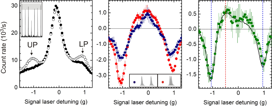
We first carry out resonant spectroscopy of the strongly coupled QD-cavity system by scanning the center frequency of the pulsed laser across the polariton spectrum (see Methods) when QD and cavity are very close to resonance. The result of a single scan is displayed as open circles in Fig. 2a for a pulse duration of 86 ps and an average signal power of 1 nW. As reported previously Reinhard:arXiv11 , we employ an off-resonant re-pump laser at a repetition rate of 1 MHz to partially counteract the laser-induced quantum-dot blinking present in the system. Due to this blinking, we obtain a three peak spectrum consisting of the upper and lower polariton peaks (UP and LP) and the uncoupled cavity peak in the middle (see Supplementary Material). In order to ensure that we work in the single-photon regime, we carried out photon auto-correlation measurements Reinhard:arXiv11 demonstrating photon antibunching, i.e. photon blockade Birnbaum:Nature05 , on both upper and lower polariton transitions to the first Jaynes-Cummings manifold (see inset of Fig. 2a).
Next, we perform two-colour spectroscopy of the strongly coupled QD-cavity system. We tune the control laser, with average power 2 nW, to the upper-polariton resonance and scan the signal laser pulse across the spectrum. For this scan, the delay of the signal pulse with respect to the control pulse was chosen to be 25 ps corresponding to the polariton lifetime. The resulting spectrum is again displayed in Fig. 2a: the filled (open) circles show the system response with (without) control laser present. The difference between the two data sets directly reflects the non-linear response of the QD-cavity system, with the reduction of the polariton signal being the most obvious effect of the presence of the control laser. We plot this difference in Fig. 2b (red data points). In addition to the fast photon-photon interactions of interest, the coupled system also exhibits a slow non-linearity caused by the laser-induced QD blinking discussed in the previous paragraph (see Supplementary Material). To distinguish between the two effects, we acquire the same spectra as in Fig. 2a but now with a time-delay of 5 ns between the control and signal pulse which is much longer than the polariton lifetime and the laser-pulse widths. The difference signal is again displayed in Figure 2b as blue bullets. Subtracting the two non-linear responses in Fig. 2b from each other yields the fast non-linear optical response from the strongly coupled QD-cavity system and is depicted in Fig. 2c: the data shows that the largest non-linear effect occurs at the spectral position of the polaritons (vertical blue lines). Here, the change in the scattering rate induced by the control laser is negative () due to saturation of the corresponding transitions. At the transition wavelength from the first to the second manifold (vertical red line), this change is positive () since the absorption of the control photon enables the subsequent scattering of a signal photon. For confirmation, we performed numerical simulations based on a Monte-Carlo wave-function (MCWF) approach with the experimental parameters as input and only the absolute amplitude of the non-linear signal determined from a least-square fit to the data (see Supplementary Material). The excellent agreement between theory (black line) and experiment clearly demonstrates that the observed positive non-linearity is indeed due to the two-colour transition to the second Jaynes-Cummings manifold. We emphasize here, that due to the finite linewidth of the coupled-system eigenstates as well as the finite bandwidth of the laser pulses there is some overlap between transitions from the first to the second and from the second to the third manifold and so forth. Hence, we expect a non-negligible contribution to the non-linear signal stemming from states higher up in the JC ladder.
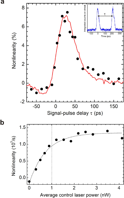
In order to demonstrate ultrafast switching by single photons, i.e. conditional scattering of signal photons on ultrafast timescales, we vary the delay between control and signal pulses while recording the (positive) non-linearity for fixed laser-detunings. As depicted in Fig. 1b, we choose the control pulse to be resonant with the fundamental upper polariton and the signal pulse to be resonant with the transition from the first to the second manifold. The result is plotted in Figure 3a for a pulse duration of 33 ps; the black dots depict experimental data, while the red curve was obtained from a MCWF simulation with the absolute amplitude extracted from a least-square fit to the data. Our single-photon switch exhibits both ultra-fast turn-on and turn-off characteristics: The sharp turn-on of the non-linear response of the QD-cavity system around zero time delay reflects the response time of the system and clearly demonstrates ultrafast switching operation of the strongly coupled device: we find that the corresponding turn-on time (the time the signal takes to rise from to of the maximum) is about 20 ps. At delay times longer than ps, the non-linear signal of Fig. 3a exhibits a fast exponential decay corresponding to the polariton lifetime which in turn determines the turn-off time of our device. The asymmetry in the pulse-delay dependence is a direct consequence of the cascaded-nature of the underlying two-photon transition.
The ultimate switching time is in principle determined by the anharmonicity of the Jaynes-Cummings spectrum, and is given by ps – close to the switching time observed in the experiment. Besides the switching speed, a quantity of interest is the transfer characteristic, i.e. the output signal as a function of control power which is plotted in Fig. 3b. Here, we recorded the signal photons scattered from the system as a function of input power of the control pulse. As expected, we first see a linear increase with control power and then saturation when the mean intra-cavity average photon number reaches .
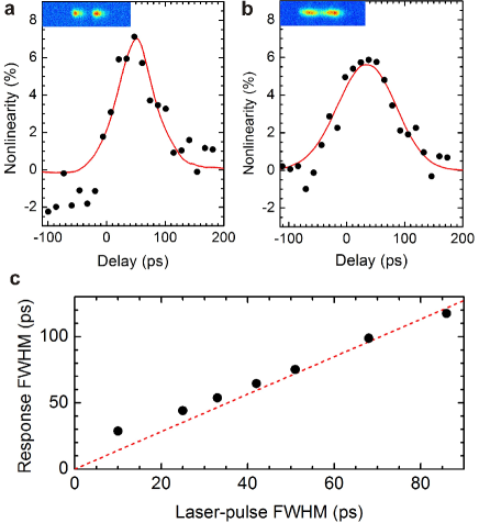
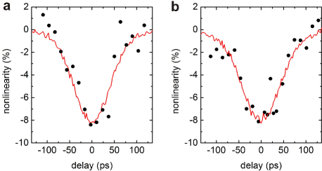
Besides the realization of single-photon switching, the strong non-linearity of the QD-cavity system can be applied for measuring pulse widths of ultrafast optical pulses down to the single-photon level. This is demonstrated in Figure 4, where we map out the non-linear system response as a function of pulse delay for pulse durations of 51 ps and 86 ps. Since the pulse widths are significantly longer than the polariton lifetime of 25 ps, the system response is more symmetric than in the case of the 33 ps pulses of Fig. 3a. We find good agreement between the pulse-delay-dependent non-linearity and the numerical convolutions of the independently obtained streak-camera images (red lines). Figure 4c compares the FWHM obtained from Monte-Carlo simulations of the non-linear system response with the FWHM of the incident (Gaussian) laser pulses. The red dashed line corresponds to the correlator width of the pulses. Above ps, the deviation of the simulated width from this line is less than – in this range our device works nicely as a single-photon pulse-correlator. Finally, we remark that single-photon switch and/or pulse-correlator operation can also be realized centering the signal pulse on the other (lower) polariton transition, which yields a larger magnitude for the non-linearity (see Fig. 2c and Supplementary Material).
A natural extension of our work would be the realization of a single-photon transistor where the presence of a single control-photon () enables the scattering of signal photons Chang:NatPhys07 ; Hwang:Nature09 . A simple calculation shows (see Supplementary Material) that if pure dephasing were absent, our QD-cavity device would exhibit a modest gain of . While increasing the ratio would already increase , high-gain () transistors may be realized in combination with EIT schemes Imamoglu:PRL97 ; Muecke:Nature10 ; Hoi:PRL11 ; Suzuki:Science11 . Another landmark achievement would be the demonstration of preservation of quantum coherence during the non-linear interaction, which could then pave the way for the realization of an ultrafast controlled-phase gate between two single-photon pulses Duan:PRL04 .
This work is supported by NCCR Quantum Photonics (NCCR QP), research instrument of the Swiss National Science Foundation (SNSF) and an ERC Advanced Investigator Grant (A.I.). The authors thank J.M. Sanchez and U. Grob for assistance in the lab. The authors declare that they have no competing financial interests. Correspondence and requests for materials should be addressed to T.V. and A.I. (E-mail: volz@phys.ethz.ch, imamoglu@phys.ethz.ch)
Methods
Pulse preparation
Both control and signal laser pulses are derived from the same mode-locked Ti:Sa laser with a pulse repetition rate of MHz and an intrinsic pulse width of a few picoseconds. The laser pulses are sent through a grating spectrometer for frequency filtering and split by a 50/50 beam splitter. Both beams are then coupled into single-mode optical fibres. The resulting spectral width of the pulses can be adjusted from 0.04 nm to 0.015 nm by an additional slit in front of the spectrometer which determines the effective NA of the spectrometer. The pulses are nearly Fourier-limited, thus we can adjust the pulse duration from about 33 ps to 86 ps. We mechanically tune the center frequency of the signal pulse by employing a piezo-driven mirror holder in front of the fibre coupler which enables coupling of different parts of the spectrum into the fibre. The center frequency of the pulse is monitored using a wavemeter, and a computer-controlled feedback loop allows for tuning. The average power of both control and signal laser beams is stabilized using acousto-optical modulators. The relative delay of the two pulses is adjusted using a motorized delay stage. Pulse shapes and delays are monitored by sending the light reflected from the sample surface to a streak camera with approximately 4 ps time resolution.
Extraction of the optical non-linearity
When applying both a control pulse at time and a signal pulse at time to the system, the time-integrated response can be written as , where and denote the number of scattered photons when only a control respectively signal laser is applied. is the total optical non-linearity, quantified as the number of additional scattered photons. Its origin is twofold: A fast () contribution arising from the anharmonicity of the Jaynes-Cummings ladder (JC) and a slow () contribution stemming from charge blinking, thus . If we choose an intermediate timescale on the order of ns, such that , then . For , and
| (1) |
In order to determine we choose , by switching an additional delay line into the path of the signal laser. In order to eliminate long-time drifts we measure , and simultaneously by switching the control and signal lasers on/off with and respectively and sorting the output photons accordingly.
References
- (1) Chang, D. E. , Sørensen A. S. , Demler E. A. & Lukin, M. A single-photon transistor using nanoscale surface plasmons. Nature Physics 3, 807-812 (2007).
- (2) Hwang, J. et al. A single-molecule optical transistor. Nature 460, 76-80 (2007).
- (3) Turchette, Q. A. et al. Measurement of Conditional Phase Shifts for Quantum Logic. Physical Review Letters 75, 4710-4713, (1995).
- (4) O’Brien, J. L. , Furusawa, A. & Vuckovic, J. Photonic quantum technologies. Nature Photonics 3, 687-695 (2009).
- (5) Schuster, I. et al. Nonlinear spectroscopy of photons bound to one atom. Nature Physics 4, 382-385 (2008).
- (6) Dayan, B. et al. A Photon Turnstile Dynamically Regulated by One Atom. Science 319, 1062-1065 (2008).
- (7) Fink, J. M. et al. Climbing the Jaynes-Cummings ladder and observing its nonlinearity in a cavity QED system. Nature 454, 315-318 (2008).
- (8) Deppe, F. et al. Two-photon probe of the Jaynes-Cummings model and controlled symmetry breaking in circuit QED. Nature Physics 4, 686-691 (2008).
- (9) Bishop, L. S. et al. Nonlinear response of the vacuum Rabi resonance. Nature Physics 5, 105-109 (2009).
- (10) Hennessy, K. et al. Quantum nature of a strongly coupled single quantum dot-cavity system. Nature 445, 896-899 (2007).
- (11) Srinivasan, K. & Painter, O. Linear and nonlinear optical spectroscopy of a strongly coupled microdisk-quantum dot system. Nature 450, 862-866 (2007).
- (12) Fushman, I. et al. Controlled phase shifts with a single quantum dot. Science 320, 769-772 (2008).
- (13) Kasprzak, J. et al. Up on the Jaynes-Cummings ladder of a quantum-dot/microcavity system. Nature Materials 9, 304-308 (2010).
- (14) Faraon, A. et al. Coherent generation of non-classical light on a chip via photon-induced tunneling and blockade. Nature Physics 4, 859-863 (2008).
- (15) Faraon, A. , Waks, E. , Englund, D. , Fushman, I. & Vuckovic J. Efficient photonic crystal cavity-waveguide coupling. Applied Physics Letters 90, 073102 (2007).
- (16) Brossard, F. S. F. et al. Strongly coupled single quantum dot in a photonic crystal waveguide cavity. Applied Physics Letters 97, 111101 (2010).
- (17) Bose, R. , Sridharan, D. , Solomon, G. & Waks, E. Observation of strong coupling through transmission modification of a cavity-coupled photonic crystal waveguide. Optics Express 19, 5398-5409 (2011).
- (18) Mabuchi, H. & Doherty, A. C. Cavity quantum electrodynamics: Coherence in context. Science 298, 1372-1377 (2002).
- (19) Birnbaum, K. M. et al. Photon blockade in an optical cavity with one trapped atom. Nature 436, 87-90 (2005).
- (20) Kubanek, A. et al. Two-Photon Gateway in One-Atom Cavity Quantum Electrodynamics. Physical Review Letters 101, 203602 (2008).
- (21) Lang, C. et al. Observation of resonant photon blockade at microwave frequencies using correlation function measurements. Physical Review Letters 106, 243601 (2011).
- (22) Reinhard, A. et al. Strongly correlated photons on a chip. arXiv 1108.3053v1 (2011).
- (23) Yoshie, T. et al. Vacuum Rabi splitting with a single quantum dot in a photonic crystal nanocavity. Nature 432, 200-203 (2004).
- (24) Reithmaier, J. P. et al. Strong coupling in a single quantum dot-semiconductor microcavity system. Nature 432, 197-200 (2004).
- (25) Peter, E. et al. Exciton-photon strong-coupling regime for a single quantum dot embedded in a microcavity. Physical Review Letters 95, 067401 (2005).
- (26) Imamoglu, A. et al. Strongly interacting photons in a nonlinear cavity. Physical Review Letters 79, 1467-1470 (1997).
- (27) Mücke, M. et al. Electromagnetically induced transparency with single atoms in a cavity. Nature 465, 755-758 (2010).
- (28) Hoi, I.-C. et al. Demonstration of a single-photon router in the microwave regime. Physical Review Letters 107, 073601 (2011).
- (29) Tanji-Suzuki, H. et al. Vacuum-induced transparency. Sciencexpress, 10.1126/science.1208066 (2011).
- (30) Duan, L.M. & Kimble, H. J. Scalable Photonic Quantum Computation through Cavity-Assisted Interactions. Physical Review Letters, 92, 127902 (2004).
Supplementary Information
Estimating typical blinking times
As described in a previous publication Reinhard:arXiv11 , our QD-cavity device exhibits significant blinking due to charging when resonantly excited with laser light. For very low excitation powers, the typical blinking time (corresponding to the lifetime of the neutral QD state in presence of laser light) was determined from auto-correlation measurements using a single APD. We find that decreases linearly with increasing average laser power. As a result, the polariton signals saturate and the number of photons scattered on the bare cavity mode increases quadratically with increasing power (see Fig. S1a). In contrast to the Jaynes-Cummings non-linearities, this non-linearity occurs on the blinking timescale .
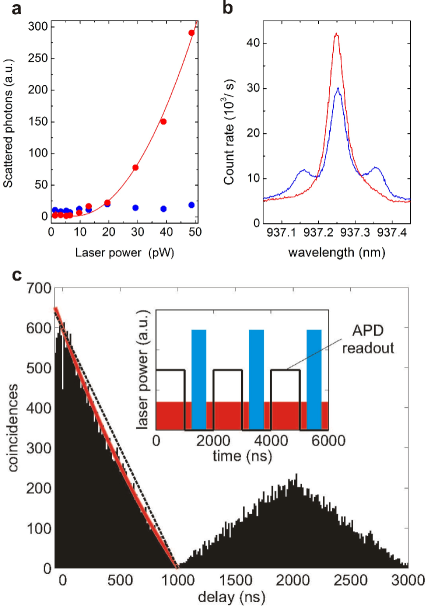
We counteract the blinking effect by shining in an off-resonant laser for re-pumping and thus partially restoring the polariton signal (see Fig. S1b). Since we find a typical blinking time on the order of a few , the re-pump laser repetition frequency is on the order of MHz. For determining at nW light levels, we record the photon auto-correlation function with a pulsed laser resonant with a polariton transition, as described in Reinhard:arXiv11 . Figure S1c displays a typical auto-correlation histogram taken on the upper polariton for an excitation power of and a re-pump pulsing rate of . As a consequence, the auto-correlation function exhibits a periodic triangular shape on the scale. The triangle at zero time delay is about a factor of 3 larger than triangles at other times. This (classical) bunching effect indicates that the system, on average, is in the desired neutral ground state after every third re-pump pulse. The detected polariton emission after a re-pump pulse is given by , if and , if . The classical auto-correlation function therefore reads as follows
| (S1) |
We fit the trailing slope of the central triangle to the formula above, resulting in a blinking time .
In the experiment described in the main text, we record the system non-linearity for two different cases. In the first case, control and signal pulses overlap in time (), in the second case, they are separated by several ns (). For the extraction of the Jaynes-Cummings optical non-linearity, we calculate (see Methods, Eqn. (1)), which is based on the assumption that the non-linearity due to charge blinking remains unchanged within time . As the above analysis shows, this is justified, since .
Calculation of the optical non-linearity
As described in the Methods section in the main text, we specify the optical non-linearity as . Here, is the delay of the signal pulse with respect to the control pulse, and , and are the number of emitted photons per pulse (pulse pair) when either both laser pulses together, only the control or only the signal laser are applied, respectively. The photon number per pulse is given by , where is the rate of emitted photons given by , where denotes the system ground state, before a laser pulse has excited the system. The system collapse operator evolves according to the non-Hermitian effective Hamiltonian , where is the cavity photon annihilation operator and are the exciton creation and annihilation operators. is the Jaynes-Cummings Hamiltonian and denotes the interaction with the Gaussian laser pulses, . denotes the cavity dissipation rate, the exciton spontaneous recombination rate and the exciton pure dephasing rate. and correspond to the maximal laser-cavity coupling rates at the peak power of control and signal pulses, with an overall system coupling efficiency included. and are calculated in the same way, with or respectively. In order to determine , we use a Monte Carlo wavefunction (MCWF) approach, as described in Molmer:JOSA93 . The calculations are performed with the experimentally determined values, , , , , and Reinhard:arXiv11 .
Cross-correlation of upper and lower polaritons
In the main text, we demonstrate a positive non-linear response of the system when driving the fundamental upper polariton transition with a control pulse and the transition from the first to the second Jaynes-Cummings manifold with a signal pulse. For pulse durations of , the width of the delay-dependent non-linearity corresponds to a very good approximation to the convolution of the original control and signal pulses. Thus, the system can serve as a single-photon pulse correlator. Similarly, one can use the two polariton transitions for demonstration of pulse-correlator operation. We carried out the corresponding experiment by exciting the upper polariton transition with the control laser and the lower polariton with the signal laser. In this case, the optical non-linearity is negative (compare Figure 2c of the main text), since the ground state population is decreased with the control/signal laser present, preventing the other laser to scatter photons on the lower/upper polariton transition, respectively. Without post-filtering the scattered photons (corresponding to the situation in our experiment), the control and signal pulses are inter-changeable without having any effect on the non-linear system response. The negative non-linear response on the polaritons is about a factor of two larger than the positive non-linearity on the transition into the second Jaynes-Cummings manifold, as can be seen in Fig. 2c of the main text. Figure S2 displays corresponding measured negative non-linear system responses as a function of pulse delay for pulse durations of (a) and (b) .
Transistor operation
As suggested in Ref. Faraon:NatPhys08 , the present device could in principle be operated as a single-photon transistor. In analogy to a conventional electronic transistor, a single-photon transistor should exhibit gain. Following Ref. Chang:NatPhys07 , at the level of single light quanta one can define the gain as the number of scattered signal photons , per incident control photon before the spontaneous relaxation of the device back into its ground (or off) state. In a three-level lambda system as considered in that article, is given by the ratio of relaxation rates (or branching ratio) of the signal and the control transition. Following this argument, one might naively expect that in a Jaynes-Cummings system the gain should be determined by the ratio of the excited state lifetimes of the first compared to the second manifold. However, due to the finite overlap of transitions between higher-lying manifolds, multiple transitions are involved in the system dynamics. If , the fundamental polariton transitions are to a certain extent spectrally separated from the rest, i.e. from the higher-lying transitions. If a weak control laser pulse is resonant with a transition from the ground state to a polariton state while a stronger signal pulse addresses the higher-lying transitions jointly, a gain larger than one is possible due to the decreasing anharmonicity for higher photon numbers. In a simple simulation using the MCWF method, we find that a Jaynes-Cummings system with (our device) can have a gain of at least and an on/off ratio of , provided pure dephasing is neglected. If is increased by a factor of 4 (as could be achieved with larger Q in state-of-the-art nano-cavities), a gain of and an on/off ratio of could be obtained. The calculated gain rapidly decreases for the experimentally observed dephasing rates. Hence, a clear experimental demonstration of transistor gain appears to be very demanding with the current system parameters.
References
- (1) Reinhard, A. et al. Strongly correlated photons on a chip. arXiv 1108.3053v1 (2011).
- (2) Molmer, K. , Castin, Y. & Dalibard, J. Monte-Carlo wave-function method in quantum optics. Journal of the Optical Society of America 10, 524-538 (1993).
- (3) Chang, D. E. , Sørensen, A. S. , Demler E. A. & Lukin, M. A single-photon transistor using nanoscale surface plasmons. Nature Physics 3, 807-812 (2007).
- (4) Faraon, A. et al. Coherent generation of non-classical light on a chip via photon-induced tunneling and blockade. Nature Physics 4, 859-863 (2008).