Ultrastrong coupling of the cyclotron transition of a two-dimensional electron gas to a THz metamaterial
Artificial cavity photon resonators with ultrastrong light-matter interactions are attracting interest both in semiconductor and superconducting systems, due to the possibility of manipulating the cavity quantum electrodynamic ground state with controllable physical properties. We report here experiments showing ultrastrong light-matter coupling in a terahertz metamaterial where the cyclotron transition of a high mobility two-dimensional electron gas is coupled to the photonic modes of an array of electronic split-ring resonators. We observe a normalized coupling ratio between the vacuum Rabi frequency and the cyclotron frequency . Our system appears to be scalable in frequency and could be brought to the microwave spectral range with the potential of strongly controlling the magnetotransport properties of a high-mobility 2DEG.
Enhancement and tunability of light-matter interaction is crucial for fundamental studies of cavity quantum electrodynamics (QED) and for applications in classical and quantum devices [1, 2, 3, 4] . The coupling between one cavity photon and one elementary electronic excitation is quantified by the vacuum Rabi frequency . The non-perturbative strong light-matter coupling regime is achieved when is larger than the loss rates of the photons and electronic excitations. Recently, growing interest has been generated by the ultrastrong coupling regime[5, 6, 7, 8, 9, 10, 11, 12], which is obtained when the vacuum Rabi frequency becomes an appreciable fraction of the unperturbed frequency of the system . In such a regime, it is possible to modify the ground and excited state properties obtaining non-adiabatic cavity QED effects [5]. Experimental progress has been achieved in two different solid-state systems : (i) microcavities embedding doped quantum wells[13, 14, 15, 16, 17], where the active electronic transition is between quantized subbands in the well; (ii) superconducting quantum circuits in transmission line resonators[18, 19], where the photon field is coupled to artificial two-level atoms obtained with Josephson junctions.
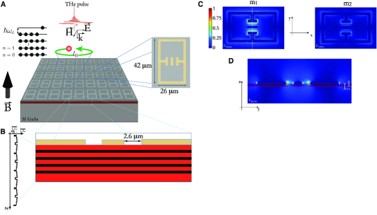
We present experimental results on a new system, namely a high-mobility two-dimensional electron gas (2DEG) coupled to terahertz (THz) metamaterial resonators. The photon mode is coupled to the magnetic cyclotron transition of the 2DEG, obtained by applying a magnetic field perpendicular to the plane of the quantum wells (Fig.1(A)). The cyclotron frequency is expressed by where is the applied magnetic field, e is the elementary charge and represents the electron effective mass. This highly controllable system is ideal for the study of strong coupling because the material excitation can be continuously tuned by changing the value of the applied magnetic field. The key physical aspect to highlight is the dependence of the optical dipole moment for a cyclotron transition on the cyclotron orbit length. The dipole scales as [20], where is the magnetic length and is the filling factor of the 2DEG , being the electron areal density. This proportionality of the dipole with respect to allows to have gigantic dipole moments as soon as the cyclotron transition can be resolved. According to theoretical calculations valid for integer filling factors and for an optimized resonator geometry, the coupling ratio is expected to scale as where is the fine structure constant and is the number of 2DEGs [20]. For high filling factors, this coupling ratio is predicted to assume values even larger than unity (corresponding to transitions in the microwave range). We use high-mobility 2DEG based on GaAs material system [21] and we realize our experiments in the THz region of the electromagnetic spectrum. These frequencies, for our material system, correspond to magnetic fields of the order of a few Tesla and optical experiments are conducted using broadband THz pulses generated with ultrafast lasers [22]. A THz-TDS system (bandwidth ) [23] is coupled to a split-coil superconducting magnet to probe sample transmission [24].
Our THz metamaterial integrates the 2DEG with a metasurface of electronic split-ring resonators (see Fig.1(A)). These resonators [26, 27, 28] exhibit electric field enhancement over strongly subwavelength volumes [29], making them ideal candidates to reach extreme couplings in the Mid-Ir and THz range where long wavelength radiation has to interact with quantum well systems typically extending over length of some micrometers [30]. Moreover, the enhanced in-plane (x-y) electric field couples efficiently to the cyclotron transition when the magnetic field is applied perpendicularly to the plane of the layers and parallel to the wavevector of the incident THz pulse (see Fig.1(A)). Resonators were deposited on top of the 2DEG by conventional photolitography, metallization with Ti/Au () and lift-off technique.
At zero magnetic field we observe two resonances m1, m2 whose origin is qualitatively different: the lowest frequency mode ( ) is attributed to the LC resonance, where counterpropagating currents circulate in the inductive part and the electric field is enhanced mainly in the capacitor gap [27]. The second mode () is attributed to the ”cut wire” behavior where a kind of resonance is excited along the sides of the metaparticle [28]. These values correspond well to simulations with 3D FE modeling (see S1 in [24]). The two modes of the split-ring resonator also have different transverse wavevectors, as it is evident looking at the different field distributions. The presence of conductive layers underneath alters the frequency and the quality factor of these resonances.
We observe a value of for an insulating substrate and when the resonator is deposited on top of the single 2DEG sample. The values for the second resonance results less affected yielding and (a more detailed analysis can be found in S1 of [24] ). It is important to highlight that, in contrast to atomic systems, we can realize strong light-matter coupling physics with resonators displaying extremely low quality factors. The giant value of the coupling constant typical of intersubband systems [5] together with the high electric field enhancement of sub-wavelength metallic resonators (V m3 in our case ) allow the observation of cavity polaritons in a system where both components are in principle highly dissipative.
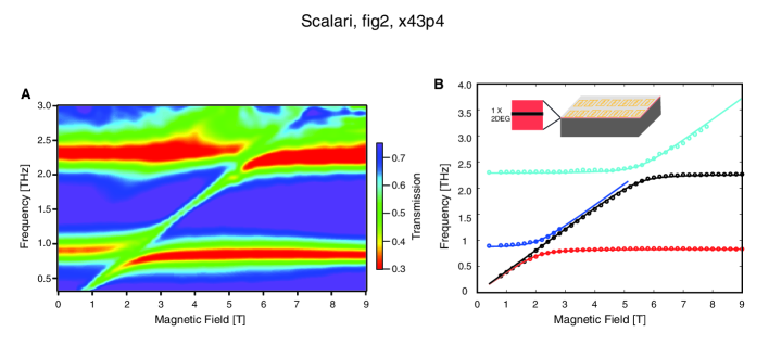
In the data reported in Fig.2(A) we observe the evolution of the sample transmission as a function of the applied magnetic field (normalized to the electric field of the reference 2DEG wafer at ) . One 2DEG (, doping density ) is used as an active medium and placed below the surface: its cyclotron resonance can couple to the resonator modes. As the magnetic field is swept a profound modification of the sample transmission is observed. The possibility to tune in a continuous way the material excitation allows to follow the evolution of polaritonic states as the system is driven from the uncoupled regime to the strongly coupled one [31]. We observe two successive anticrossings when the cyclotron energy matches the first and the second resonator modes.
In Fig. 2(B) we extract the positions of the minima of sample transmission and plot the dispersion curves for the polariton eigenvalues as a function of the magnetic field. The curves are calculated using a full quantum mechanical treatment of the system, obtained generalizing the theory described in Ref.[20] to the case of a zero-dimensional resonator exhibiting two modes with different transverse wavevectors [24]. Following a bosonization procedure, we have derived the different contributions to the total Hamiltonian and have diagonalized it using the Hopfield-Bogoliubov method. It is worth mentioning that the ideal resonator we have considered in the analytical treatment is different from the real split-ring one. However, we emphasize that this would introduce only a form factor in the matrix element calculation.
In order to fit the experimental data, we need to know the resonator modes frequencies ( and ) as well as the strength of their couplings ( and ). For each cavity mode we assumed the asymptotic value of the corresponding lower polariton branch to coincide with the frequency of the unloaded resonator ( THz and THz) [20, 24] . The coupling strength for the two modes can not be directly measured, we thus applied a best fit procedure following the least square method, analogously to what done in Ref. [14] (more details in S3 of [24]). The minimal error [24] is obtained for and (where and ). As expected the coupling strength scales monotonously with : for the measured density , we have for the first mode and for the second one.
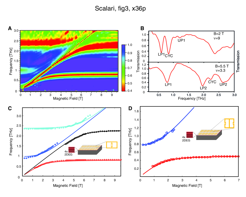
To increase the coupling strength, we kept the resonator geometry and hence the frequency constant, and increased the effective number of carriers in the system. A new sample was prepared with wells and a doping density per well (see scheme in Fig. 1(B) and materials and methods in [24]). Sample transmission as a function of the applied magnetic field (Fig.3(A)) shows that the system is driven deeply into the ultrastrong coupling regime. The polaritonic line widths display narrowing as the low quality cavity mode is mixed with the cyclotron resonance (Fig.3(B)). Following the fitting procedure previously described we observe a value of for the first resonance. Indeed, the effects of the anti-resonant terms of the light-matter Hamiltonian start becoming relevant when the dimensionless ratio is of the order of [14]. Due to the increased doping, the filling factor in the region of the anti crossing is . As expected, the coupling ratio scales with and for the two samples at the same resonant frequency we obtain experimentally and theoretically . The small discrepancy can be attributed to the different coupling of the quantum wells which do not experience the same electric field of the resonator: the generalized expression of the coupling ratio is calculated in the case when all the wells are coupled in the same way to the resonator’s field [20].
By further scaling the resonator frequency down to GHz employing a slightly modified geometry (see inset Fig.3(D), section S2 and Fig. S5 of [24] ) and employing the sample with n quantum wells we could probe the regime where the polariton splitting at the anticrossing is larger than the bare cavity photon energy. In Fig.3(D) we report the positions of the minima of the sample transmission for the case of f=500 GHz resonator together with the fitted dispersion curves: we measure a normalized ratio for a filling factor of which corresponds to (see also Fig.S6 in [24] ).
The generalization of the theory developed in Ref. [20] accounts for the depolarization shift in presence of a magnetic field (magnetoplasmon) originating from the long-wavelength part of the Coulomb interaction. We found that the renormalization of the cyclotron transition frequency is too small to allow the experimental resolution of the magnetoplasmon branch (see Figs 2(A) and 3(A)) in our experimental parameter regime including the small wavevector condition which is always satisfied since dealing with optical wavevectors.
We have observed ultrastrong light matter coupling in a composite THz metamaterial measuring a normalized coupling ratio . The impact of our results has to be considered also in the perspective of a change in the DC transport properties of the 2DEG, in analogy with what already observed by direct irradiation at lower frequencies [32].
These results should lead to the scaling of the frequency to lower values and to an increase of effective density to further enhance the coupling strength.
References and Notes
- [1] J. Raimond, M. Brune, and S. Haroche, Rev. Mod. Phys. 73, 565 (2001).
- [2] A. Wallraff et al., Nature 431, 162 (2004).
- [3] S. Christopoulos et al., Phys. Rev. Lett. 98, 1126405 (2007).
- [4] K. Hennessy et al., Nature 445, 896 (2007).
- [5] C. Ciuti, G. Bastard, and I. Carusotto, Phys. Rev. B 72, 115303 (2005).
- [6] C. Ciuti and I. Carusotto, Phys. Rev. A 74, 033811 (2006).
- [7] S. De Liberato, C. Ciuti, and I. Carusotto, Phys. Rev. Lett. 98, 103602 (2007).
- [8] M. H. Devoret, S. M. Girvin, and R. J. Schoelkopf, Annalen der Physik 16, 767 (2007).
- [9] J. Bourassa, J. M. Gambetta, A. A. Abdumalikov, O. Astafiev, Y. Nakamura, and A. Blais, Phys. Rev. A 89, 032109 (2009).
- [10] V. M. Muravev, I. V. Andreev, I. V. Kukushkin, S. Schmult,and W. Dietsche, Phys. Rev. B 83, 075309 (2011).
- [11] T. Schwartz, J. A. Hutchinson, C Genet ,and T. W. Ebbesen, Phys. Rev. Lett. 106, 196405 (2011).
- [12] P. Nataf and C. Ciuti, Phys. Rev. Lett. 104, 02360 (2010).
- [13] D. Dini, R. Köhler, A. Tredicucci, G. Biasiol, and L. Sorba, Phys. Rev. Lett. 90, 116401 (2003).
- [14] A. Anappara, et al., Phys. Rev. B 79, 201303 (2009).
- [15] G. Guenter et al., Nature 458, 178 (2009).
- [16] Y. Todorov et al., Phys. Rev. Lett. 105, 196402 (2010).
- [17] M. Geiser et al., Appl. Phys. Lett. 97, 191107 (2010).
- [18] T. Niemczyk et al., Nature Physics 6, 772 776 (2010).
- [19] P. Forn-D az et al., Phys. Rev. Lett. 105, 237001 (2010).
- [20] D. Hagenmüller, S. De Liberato, and C. Ciuti, Phys. Rev. B 81, 235303 (2010).
- [21] V. Umansky, M. Heiblumn, Y. Levinson, J. Smet, J. Nubler, and M. Dolev, J. Cryst. Growth 278, 1658 (2005).
- [22] P. Smith, D. Auston, and M. Nuss, IEEE J. Quantum Electron. 24, 255 (1988).
- [23] D. Grischkowsky, S. Keiding, M. van Exter, and C. Fattinger, JOSA B 7, 2006 (1990).
- [24] Supporting material is available on Science online
- [25] J. O Hara, E. Smirnova, A. Azad, H. Chen, and A. J. Taylor, Active and Passive Electronic components (2007), doi:10.1155/2007/49691.
- [26] D. Schurig et al., Science 314, 977 (2006).
- [27] H.-T. Chen, W. J. Padilla, J. Zide, A. Gossard, A. Taylor, and R. Averitt., Nature 444, 597 (2006).
- [28] W. J. Padilla, A. J. Taylor, C. Highstrete, M. Lee, and R. D. Averitt, Phys. Rev. Lett. 96, 107401 (2006).
- [29] C. Walther, G. Scalari, M. I.Amanti, M. Beck, and J Faist, Science. 327, 1495 (2010).
- [30] D. Shelton et al., ACS Nano Lett. 11, 2104 (2011).
- [31] The magnetic tunability has been studied in the very different system of exciton-polaritons in the near-infrared, see J. Tignon et al., Phys. Rev. Lett. 74, 3967 (1995).
- [32] R. Mani, J. Smet, K. von Klitzing, V.Narayanamurti, W. Johnson, and V.Umansky, Nature 420, 646 (2002).
- [33] H.-T. Chen, J. Zide, A. Gossard, A. Taylor, R. Averitt and W. J. Padilla, Optics Express 15, 1084 (2007).
- [34] B. Deveaud, Wiley-VCH , The physics of semiconductor micro cavities (2007).
- [Acknowledgements] : This research was supported by the Swiss National Science Foundation (SNF) through the National Centre of Competence in Research Quantum Science and Technology and through the SNF grant n. 129823. We would like to thank J.Lloyd-Hughes and K.Ohtani for their help and S. S. Dhillon for discussions. C. C. is member of Institut Universitaire de France.