The influence of anisotropic gate potentials on the phonon induced spin-flip rate in GaAs quantum dots
Abstract
We study the anisotropic orbital effect in the electric field tunability of the phonon induced spin-flip rate in quantum dots (QDs). Our study shows that anisotropic gate potential enhances the spin-flip rate and reduces the level crossing point to a lower QDs radius due to the suppression of the Land g-factor towards bulk crystal. In the range of V/cm, the electric field tunability of the phonon induced spin-flip rate can be manipulated through strong Dresselhaus spin-orbit coupling. These results might assist the development of a spin based solid state quantum computer by manipulating spin-flip rate through spin-orbit coupling in a regime where the g-factor changes its sign.
Controlling the single electron spins in QDs through the application of anisotropic gate potential is important for the design of solid state quantum computer. Takahashi et al. (2010); Kanai et al. (2011); Marquardt et al. (2011) Tunability of the phonon induced spin-flip rate and the electron g-factor in III-V semiconductor QDs can be manipulated through the application of externally applied gate potentials. de Sousa and Das Sarma (2003); Khaetskii and Nazarov (2001); Prabhakar and Raynolds (2009); Pryor and Flatté (2006) The strength of the Rashba-Dresselhaus spin-orbit coupling is determined by the asymmetric triangular quantum well along z-direction which approximately estimates the density of electrons at the heterojunction. de Sousa and Das Sarma (2003); Prabhakar et al. (2010) Rashba spin-orbit coupling arises from the structural inversion asymmetry along the growth direction and Dresselhaus spin-orbit coupling arises from bulk inversion asymmetry in the crystal lattice. Bychkov and Rashba (1984); Dresselhaus (1955)
Recently, it has been made possible to measure the electron spin states in gated QDs in presence of magnetic fields along arbitrary direction. Takahashi et al. (2010) The physics behind this has been theoretically investigated by authors in Refs. Nowak et al., 2011; Prabhakar, Raynolds, and Melnik, 2011 which confirms that the spin-orbit coupling can be used as a control parameter in the electric field and magnetic field tunability of the electron g-factor tensor. The authors in Refs. Elzerman et al., 2004; Kroutvar et al., 2004 measured the long spin relaxation times, approximately 0.85 ms in GaAs QDs by pulsed relaxation rate measurements and approximately 20 ms in InGaAs QDs by optical orientation measurements. These spin-flip rate measurements in QDs confirm the theoretical predictions of the suppression of the phonon induced spin-flip rate by spin-orbit coupling with respect to the environment. Golovach, Khaetskii, and Loss (2004); Khaetskii and Nazarov (2000); Prabhakar et al. (2010) Our work is along the lines of Refs. de Sousa and Das Sarma, 2003; Bulaev and Loss, 2005a, b with several new important findings. In particular, in this paper, we study the anisotropic orbital effect on the phonon induced spin-flip rate for a system where the area of the symmetric and asymmetric QDs kept constant. Based on both theoretical and finite element numerical simulation methods, we find that the anisotropic potential enhances the spin flip rate and reduces the level crossing point to a lower quantum dot radius due to the suppression of the g-factor towards bulk crystal.
We consider 2D anisotropic semiconductor QDs formed in the conduction band in the presence of magnetic field B along z-direction. The total Hamiltonian of an electron in the conduction band under the Kane model Pikus and Pikus (1995); Khaetskii and Nazarov (2001) can be written as
| (1) | |||
| (2) | |||
| (3) |
where is the 2D electron momentum operator in the asymmetric gauge and is the Zeeman frequency. Also, is the effective mass, is the Bohr magneton, is the Pauli spin matrices, is the strength of the parabolic confining potential with quantum dot radius . The externally applied gate potential () in our theoretical model defines the lateral size of the QDs along x- and y-directions in the plane of 2DEG. By chosing nm, we mimic the experimentally reported lateral size of the QDs in Refs. Takahashi et al., 2010; Thornton et al., 1998 and the potential induced in this range is much lower than the break down voltage ( kV/cm) in GaAs heterojunctions. The strength of the Rashba and Dresselhaus spin-orbit couplings is determined by the relation which tells us that at the electric field V/cm. In the range of V/cm, only the Dresselhaus spin-orbit coupling has an appreciable contribution in the manipulation of spin-flip rate in QDs. The asymmetric triangular quantum well potential () arises along the growth direction and usually has a major contribution to the E-filed tunability of the g-factor and spin-flip rate due to the interplay between Rashba-Dresselhaus spin-orbit couplings. The expression estimates the average thickness of the 2DEG where one can estimate the vertical average height of the QDs. de Sousa and Das Sarma (2003); Prabhakar, Raynolds, and Melnik (2011) By chosing V/cm, we estimate the average height of the QDs from nm to nm which is in the range of experimentally reported values. Thornton et al. (1998)
The above Hamiltonian (1) can be exactly diagonalized Schuh (1985); Galkin, Margulis, and Shorokhov (2004) and spin-orbit Hamiltonian can be used perturbatively to find the energy states of the QDs. The energy spectrum can be written as
and H.c. represents the Hermitian conjugate. Also, , , and is the cyclotron frequency.
We now turn to the calculation of the phonon induced spin relaxation rate in between two lowest energy states in QDs. The interaction between electron and piezo-phonon can be written as Khaetskii and Nazarov (2000, 2001)
| (4) |
Here, is the crystal mass density, is the volume of the QDs, creates an acoustic phonon with wave vector and polarization , where are chosen as one longitudinal and two transverse modes of the induced phonon in the dots. Also, is the amplitude of the electric field created by phonon strain, where and for . The polarization directions of the induced phonon are , and . Based on the Fermi Golden Rule, the phonon induced spin transition rate in the QDs is given by de Sousa and Das Sarma (2003); Khaetskii and Nazarov (2001)
| (5) |
where , are the longitudinal and transverse acoustic phonon velocities in QDs. The matrix element for the spin-flip rate between the Zeeman sublevels with the emission of phonon has been calculated perturbatively. Khaetskii and Nazarov (2001); Stano and Fabian (2006)
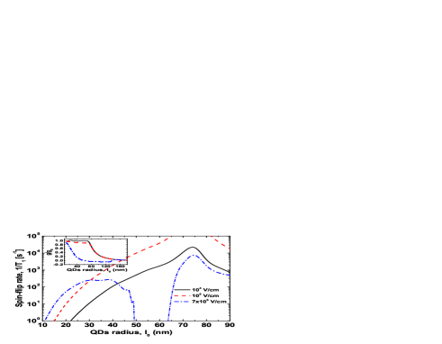
In Fig. 1, we quantify the influence of the Rashba-Dresselhaus spin-orbit admixture mechanism on the phonon induced spin-flip rate as a function of quantum dot radius for symmetric QDs. For the electric fields and V/cm (shown by solid and dashed lines), we find that the transition time between spin up and down states increases with the increase in QDs radius and gives the level crossing point at nm. For the case V/cm (shown by dashed dotted line), the spin relaxation rate in QDs starts decreasing at nm because Zeeman spin splitting energy is very small which implies small phonon density of states. It becomes negligible at nm, and thus the spin relaxation rate turns to be zero. The spin relaxation time starts increasing at nm. However, in this regime, the opposite spin state is dominating because the g-factor of an electron spin states changes their sign (see inset plots). This is an important result for the design of spin based logic devices. Indeed, in GaAs/AlGaAs QDs, wavefunctions of electrons penetrate from GaAs QDs to AlGaAs barrier with the application of gate controlled electric fields where the g-factor of an electron changes its sign. Jiang and Yablonovitch (2001); Yang and Chang (2005); Chang, Xia, and Peeters (2003) The level crossing takes into account, due to mixing, the Zeeman spin states and in QDs. The crossing point is theoretically investigated by the condition Bulaev and Loss (2005a, b) i.e., (see Eq. The influence of anisotropic gate potentials on the phonon induced spin-flip rate in GaAs quantum dots). Substituting T in the above condition, gives the crossing point at nm. Theoretically investigated level crossing point is in agreement with the numerically investigated values in the spin flip rate (see Fig. 1). It can be seen that enhancement in the spin-flip rate occurs with the increase in electric fields. The level crossing point in the spin-flip rate is not affected by the electric fields which tells us that the level crossing point found in the spin flip rate is a purely orbital effect and is independent of the Rashba-Dresselhaus spin-orbit interaction.
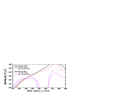
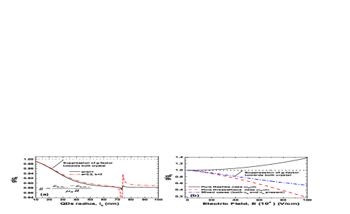
Fig. 2 explores the influence of anisotropic effects on the spin-flip rate vs. QD radius for the electric fields and V/cm. It can be seen that the anisotropic potential () enhances the spin-flip rate by approximately one half order of magnitude compared to that of symmetric potentials (). Note that we chose the above confining potentials in such a way that the area of the symmetric and asymmetric QDs are held constant. The level crossing point determined by the condition for anisotropic QDs is smaller than for the case of isotropic QDs if we held the area of the QDs constant. The crossing point for symmetric QDs was first studied by the authors of Refs. Bulaev and Loss, 2005a, b. However, in this paper, we present the condition of the level crossing point for asymmetric QDs and by utilizing both theoretical and numerical methods, we report that the anisotropic potential reduces the level crossing point to a smaller QD radius as well as to smaller magnetic fields. Similar to Fig. 1, at the electric field V/cm for anisotropic QDs in Fig. 2 (dotted lines), small Zeeman energy implies negligible phonon density of states which gives zero spin flip rate at nm and the g-factor with opposite sign (spin states change their sign) is observed at nm. Note that these numerically estimated values (zero spin-flip rate and the g-factor with opposite sign) occur at smaller QD radii for anisotropic QDs than in isotropic QDs. This tells us that the anisotropic potential leads to the quenching effect in the orbital angular momentum Pryor and Flatté (2006) that pushes the g-factor of an electron towards the bulk crystal which causes the level crossing point to occur at a smaller QD radius for anisotropic QDs (see Fig. 3(a)). From Fig. 3(b), we see that the g-factor can be tuned with the spin-orbit interactions. Recall that the electric field controls the strength of Rashba and Dresselhaus spin-orbit couplings (see Eq. 3). Here, we again see that the suppression of g-factor towards bulk crystal induces the anisotropic effect due to the interplay between Rashba-Dresselhaus spin-orbit couplings. Liu et al. (2011); Sheng and Chang (2006)
To conclude, we have shown that the electron spin states in the phonon induced spin-flip rate can be manipulated with the application of externally applied anisotropic gate potentials in QDs. The anisotropic potential causes the suppression of the g-factor towards bulk crystal that causes the enhancement of the spin-flip rate and reduces the level crossing point to a smaller QD radius. At sufficiently large electric fields, the phonon induced spin-flip rate can be tuned with Dresselhaus spin-orbit coupling by controlling the electron spin states in a regime where the g-factor changes its sign.
This work has been supported by NSERC and CRC programs (Canada) and by MICINN Grants No. FIS2008- 04921-C02-01 and FIS2011-28838-C02-01 (Spain).
References
- Takahashi et al. (2010) S. Takahashi, R. S. Deacon, K. Yoshida, A. Oiwa, K. Shibata, K. Hirakawa, Y. Tokura, and S. Tarucha, “Large Anisotropy of the Spin-Orbit Interaction in a Single InAs Self-Assembled Quantum Dot,” Phys. Rev. Lett. 104, 246801 (2010).
- Kanai et al. (2011) Y. Kanai, R. S. Deacon, S. Takahashi, A. Oiwa, K. Yoshida, K. Shibata, K. Hirakawa, Y. Tokura, and S. Tarucha, “Electrically tuned spin-orbit interaction in an InAs self-assembled quantum dot,” Nature Nanotechnology 6, 511 (2011).
- Marquardt et al. (2011) B. Marquardt, M. Geller, B. Baxevanis, D. Pfannkuche, A. D. Wieck, D. Reuter, and A. Lorke, “Transport spectroscopy of non-equilibrium many-particle spin states in self-assembled quantum dots,” Nature Communications 2, 209 (2011).
- de Sousa and Das Sarma (2003) R. de Sousa and S. Das Sarma, “Gate control of spin dynamics in III-V semiconductor quantum dots,” Phys. Rev. B 68, 155330 (2003).
- Khaetskii and Nazarov (2001) A. V. Khaetskii and Y. V. Nazarov, “Spin-flip transitions between Zeeman sublevels in semiconductor quantum dots,” Phys. Rev. B 64, 125316 (2001).
- Prabhakar and Raynolds (2009) S. Prabhakar and J. E. Raynolds, “Gate control of a quantum dot single-electron spin in realistic confining potentials: Anisotropy effects,” Phys. Rev. B 79, 195307 (2009).
- Pryor and Flatté (2006) C. E. Pryor and M. E. Flatté, “Landé factors and orbital momentum quenching in semiconductor quantum dots,” Phys. Rev. Lett. 96, 026804 (2006).
- Prabhakar et al. (2010) S. Prabhakar, J. Raynolds, A. Inomata, and R. Melnik, “Manipulation of single electron spin in a GaAs quantum dot through the application of geometric phases: The Feynman disentangling technique,” Phys. Rev. B 82, 195306 (2010).
- Bychkov and Rashba (1984) Y. A. Bychkov and E. I. Rashba, “Oscillatory effects and the magnetic susceptibility of carriers in inversion layers,” J. Phys. C: Solid State Phys. 17, 6039 (1984).
- Dresselhaus (1955) G. Dresselhaus, “Spin-orbit coupling effects in zinc blende structures,” Phys. Rev. 100, 580 (1955).
- Nowak et al. (2011) M. P. Nowak, B. Szafran, F. M. Peeters, B. Partoens, and W. J. Pasek, “Tuning of the spin-orbit interaction in a quantum dot by an in-plane magnetic field,” Phys. Rev. B 83, 245324 (2011).
- Prabhakar, Raynolds, and Melnik (2011) S. Prabhakar, J. E. Raynolds, and R. Melnik, “Manipulation of the Landé factor in InAs quantum dots through the application of anisotropic gate potentials: Exact diagonalization, numerical, and perturbation methods,” Phys. Rev. B 84, 155208 (2011).
- Elzerman et al. (2004) J. M. Elzerman, R. Hanson, L. H. Willems van Beveren, B. Witkamp, L. M. K. Vandersypen, and L. P. Kouwenhoven, “Single-shot read-out of an individual electron spin in a quantum dot,” Nature 430, 431 (2004).
- Kroutvar et al. (2004) M. Kroutvar, Y. Ducommun, D. Heiss, M. Bichler, D. Schuh, G. Abstreiter, and J. J. Finley, “Optically programmable electron spin memory using semiconductor quantum dots,” Nature 432, 81 (2004).
- Golovach, Khaetskii, and Loss (2004) V. N. Golovach, A. Khaetskii, and D. Loss, “Phonon-induced decay of the electron spin in quantum dots,” Phys. Rev. Lett. 93, 016601 (2004).
- Khaetskii and Nazarov (2000) A. V. Khaetskii and Y. V. Nazarov, “Spin relaxation in semiconductor quantum dots,” Phys. Rev. B 61, 12639–12642 (2000).
- Bulaev and Loss (2005a) D. V. Bulaev and D. Loss, “Spin relaxation and decoherence of holes in quantum dots,” Phys. Rev. Lett. 95, 076805 (2005a).
- Bulaev and Loss (2005b) D. V. Bulaev and D. Loss, “Spin relaxation and anticrossing in quantum dots: Rashba versus Dresselhaus spin-orbit coupling,” Phys. Rev. B 71, 205324 (2005b).
- Cardona, Christensen, and Fasol (1988) M. Cardona, N. E. Christensen, and G. Fasol, “Relativistic band structure and spin-orbit splitting of zinc-blende-type semiconductors,” Phys. Rev. B 38, 1806 (1988).
- Pikus and Pikus (1995) F. G. Pikus and G. E. Pikus, “Conduction-band spin splitting and negative magnetoresistance in heterostructures,” Phys. Rev. B 51, 16928 (1995).
- Thornton et al. (1998) A. S. G. Thornton, T. Ihn, P. C. Main, L. Eaves, and M. Henini, “Observation of spin splitting in single inas self-assembled quantum dots in AlAs,” Applied Physics Letters 73, 354 (1998).
- Schuh (1985) B. Schuh, “Algebraic solution of a non-trivial oscillator problem,” J. Phys. A: Math. Gen. 18, 803 (1985).
- Galkin, Margulis, and Shorokhov (2004) N. G. Galkin, V. A. Margulis, and A. V. Shorokhov, “Photoconductance of quantum wires in a magnetic field,” Phys. Rev. B 69, 113312 (2004).
- Stano and Fabian (2006) P. Stano and J. Fabian, “Orbital and spin relaxation in single and coupled quantum dots,” Phys. Rev. B 74, 045320 (2006).
- Stano and Fabian (2005) P. Stano and J. Fabian, “Spin-orbit effects in single-electron states in coupled quantum dots,” Phys. Rev. B 72, 155410 (2005).
- Jiang and Yablonovitch (2001) H. W. Jiang and E. Yablonovitch, “Gate-controlled electron spin resonance in GaAs/AlxGa1-xAs heterostructures,” Phys. Rev. B 64, 041307 (2001).
- Yang and Chang (2005) W. Yang and K. Chang, “Spin relaxation in diluted magnetic semiconductor quantum dots,” Phys. Rev. B 72, 075303 (2005).
- Chang, Xia, and Peeters (2003) K. Chang, J. B. Xia, and F. M. Peeters, “Magnetic field tuning of the effective g factor in a diluted magnetic semiconductor quantum dot,” Appl. Phys. Lett. 82, 2661 (2003).
- Liu et al. (2011) Y. Liu, F. Cheng, X. J. Li, F. M. Peeters, and K. Chang, “Tuning of anisotropy in two-electron quantum dots by spin-orbit interactions,” Applied Physics Letters 99, 032102 (2011).
- Sheng and Chang (2006) J. S. Sheng and K. Chang, “Spin states and persistent currents in mesoscopic rings: Spin-orbit interactions,” Phys. Rev. B 74, 235315 (2006).