Further author information: (Send correspondence to:)
E-mail: virgilli@fe.infn.it, frontera@fe.infn.it, valsan@fe.infn.it, liccardo@fe.infn.it
Laue lenses for hard X–/soft –rays: new prototype results
Abstract
We present the results obtained with the new Laue lens prototype built in the LARIX facility in the Physics Department of University of Ferrara. Following the results of the first prototype presented at the SPIE conference in Marseille, and also thanks to the methods adopted for improving the prototype (SPIE conference in San Diego, Ferrari et al. 2009) here we present the results of the new prototype with improved performances in terms of point spread function (PSF) and spectral response.
keywords:
Laue lenses, focusing telescopes, gamma-rays, astrophysics1 INTRODUCTION
Here we report on the status of the HAXTEL project (HArd X-ray TELescope) devoted to developing the technology for building broad energy passband (70/100–600 keV) Laue lenses, highlighting test results of the new lens prototype.
We propose a Laue lens as a new focusing instrument in the soft gamma–ray band (for an exhaustive review of Laue lenses see Ref. [1]). Laue lenses principle exploit the interference between the periodic nature of the electromagnetic radiation and the periodic atomic displacement as that typical of crystal lattice sructure. In a Laue lens, photons pass through the full crystal, using its entire volume for interacting coherently. In order to be diffracted, incoming gamma–ray radiation must satisfy the Bragg condition:
| (1) |
where dhkl is the spacing between the lattice planes (defined by the Miller indices ), is the diffraction order, keV , and is the diffracted energy at a given Bragg angle .
A Laue lens for astrophysical applications is made of a number of crystals, in transmission configuration (Laue geometry), placed so as to focus the incident radiation onto a common focal spot. A convenient way to visualize the geometry of a crystal lens is to consider it as a part of a sphere, covered with crystal tiles having their diffracting planes perpendicular to the tangent plane to the sphere. The focal spot position lying on the lens axis defines the so called focal length of the lens which is at a distance from the spherical apex, being its curvature radius.
2 Crystal properties and tile selection
The tiles used for building the prototype are mosaic crystals made of Copper with a cross section of mm2 and 3 mm thick. The lattice planes used for the diffraction are those related to the Miller indices (111).
Mosaic crystals are mainly described by mosaicity , crystallite size and effective thickness . The mosaicity is an intrinsic property of the single tile and in principle is the same for each crystal, given that each of them comes from the same ingot. Imperfection during the cutting process and at microscopic level can give rise to a different set of mosaicities. The best cristallite size that provide the best reflectivity should be at most of the order of ten of m. Unfortunately also Cu (111) microcrystals beyond 200 micron have been reported [2].
We estimated the parameters of each crystal tile by using the measured reflectivity and comparing it with the expected reflectivity function (see Refs. [3] and [1] and references therein), after taking into account the beam divergence.
Indeed, due to the beam divergence, the crystal is hit on its surface with different Bragg angles and this affects the response function which is broader than that expected as a result of the crystal mosaicity. If one ignores the correction for the divergence effect, mosaicity values higher than 6 arcmin and crystallite sizes from 200 to 400 m are derived. By correcting for the divergence effect, significant lower parameter values are obtained ( = 2.0–3.0 arcmin; t0 = 30–70 micron).
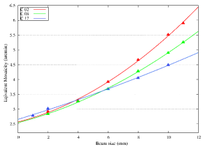
The divergence–corrected results were also tested with an experimental procedure. For a subset of crystal tiles, lower and lower beam divergence values, obtained by decreasing the beam size from 1010 mm2 to 22 mm2, were obtained and the corresponding reflectivity measured. Without taking into account the correction for divergence, we derived the gross mosaicity (called ) dependence on beam divergence shown in Fig. 1. As can be clearly seen, as the divergence converges to zero (beam size approaching to 0), the equivalent mosaicity reaches the crystal mosaicity. With this method, for the subset of 3 chosen crystals (No. 2, 8, 17), we estimated a crystal mosaicity of 2.57, 2.55 and 2.68 arcmin, respectively, These values are in good agreement with the that estimated with the divergence corrected fitting procedure (2.72, 2.48 and 2.84 arcmin).
3 The Lens assembly technique and its development facility
Details of the lens assembling steps have already been reported [4, 5, 6]. In short, the adopted lens assembling technique is based on the use of a counter-mask provided with holes, two for each crystal tile. Each tile is placed on the counter-mask by means of two pins, steadily glued to the tile, that are inserted in the counter-mask holes. The pin axis direction and the lattice planes of each crystal tile have to be exactly coincident.
The hole direction constrains the energy of the photons diffracted by the tile, while the relative position of two holes for each crystal in the counter-mask establishes the azimuthal orientation of the mean crystal lattice plane, that has to be orthogonal to the lens axis. Depending on the counter-mask shape, and mainly on the direction of the hole axes, the desired geometry of lens can be obtained. In the case of a lens for space astronomy, the hole axes have to be all directed toward the center of curvature of the lens. In the case of the developed prototype model, the hole axis is set parallel to that of the lens axis. This choice has been made to illuminate the entire lens with the available polychromatic hard X-ray source placed at 6 m far from the lens.
Once the average direction of the chosen lattice planes (111) of each Cu mosaic crystal tile has been determined, the two pins are inserted in a pin-holder which is preliminary made parallel to the hard X-ray beam. Then the pins are glued to the crystal tile (see section 4.1).
Once all the crystals are positioned on the counter-mask, a carbon fiber frame is placed above the counter-mask/crystal structure and glued to the entire set of crystals. The lens frame, along with the crystals, is thus separated from the counter-mask and the glued pins are subsequently unscrewed from an aluminum glued head.
The lens assembly apparatus is installed in the LArge Italian X-ray Facility (LARIX) located in the Physics Department of Ferrara. In addition to a set of devices employed for the specific project, the facility includes an X-ray generator with a fine focus of 0.4 mm radius with a maximum voltage of 150 kV and a maximum power of 200 W. The photons coming out from the X-ray tube are directed towards a collimator aperture which can be remotely adjusted in two orthogonal directions for beam size optimization. The lens building phase and performance test are performed by means of two detectors: an X-ray imaging detector with spatial resolution of 300 m and a cooled HPGe spectrometer with a 200 eV spectral resolution. Both are located on a rail and can be moved back and forth along the beam axis. They are used to collect direct photons and those diffracted from the crystal tiles.
4 Improvements with the new prototype
After the development of the first prototype described in Ref. [4], new improvements and tests have been performed in terms of assembling technology and of knowledge of the error budget introduced by each single step of the entire assembly process. A description of the improvements and changes have concerned the following topics.
4.1 Alignment of the pin-holder
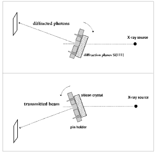
The pinholder direction is preliminary made parallel to the X-ray beam axis and thus to the direction of the average crystalline lattice planes by means of a Silicon perfect crystal which is mechanically coupled with the pinholder. The alignment procedure for silicon is the same employed for each copper crystal tile by means of Laue diffraction (see Fig. 2 for a schematic view of the alignment) and it is performed using the lattice planes (220), which are orthogonal to the crystal external surface.
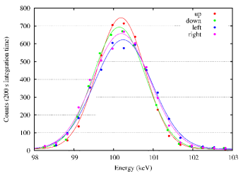
The chosen lattice plane direction of the Silicon is obtained when exactly the same energy (typically 100 keV) is diffracted with the crystal rotated at left and right around the crystal vertical axis. The verticality of the lattice planes is established from the image position of the crystal obtained when it is rotated at left and right direction. The diffracted spectrum when the crystal is rotated upward and downward around its horizontal axis confirms the chosen lattice plane verticality. Figure 3 shows the results of the achieved alignment: all the diffracted spectra of the polychromatic beam have a Gaussian profile with a full width at half maximum (fwhm) consistent with the spectral resolution of the detector and a centroid energy consistent with each other (Eup = 100.19 keV, Edown = 100.14 keV, Eleft = 100.24 keV, Eright = 100.20 keV).
Being the silicon crystal mechanically coupled with the pinholder, and being the pinholder alignment made within a tolerance better than 30 arcsec, which is related to the working tolerance of the drilled holes, the uncertainty in the lattice plane determination is mainly due to the mechanical coupling between silicon crystal and pinholder.
4.2 Pin shape and manufacturing
As a reference for the beam axis and thus of the chosen lattice plane direction, 2 pins are glued on each crystal. The gluing phase is one of the most delicate part of the process because of the subsequent separation of the glued pins from the pinholder and of the final step of removing crystals from the counter-mask.
As already reported [6], different pin shapes have been tested. For building the first prototype, we used the cylindrical pin geometry. Later, to decrease the friction between pins and pinholder during the separation phase, instead of using two cylindrical pins, we tested a single pin with conical shape and elliptical cross-section for each crystal tile . This geometry did not give positive results. The post-gluing tests showed a systematic mismatch between left and right diffracted energies, even greater than 2 keV with respect to the pre-gluing energies. For comparison, the same pre/post gluing energies obtained with the cylindrical pins give a E 0.3 keV. We concluded that the lower strength of the crystal–pin coupling, due to the smaller gluing surface is not compensated by the lower friction between pin and pinholder.
4.3 New counter-mask and carbon fiber support
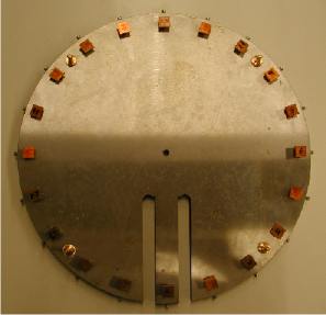
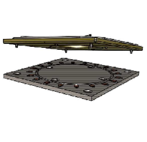
The new lens prototype consists of 20 mosaic crystals of Copper (111), with a mosaic spread of 2 to 3 arcmin. The crystal tiles are arranged in a ring configuration with a diameter of 36 cm, like the first one [4]. The lens is assembled by means of a counter-mask (Fig. 4) in which 20 pairs of holes are drilled with a radial orientation. Each crystal tile is positioned on the counter-mask by inserting its two cylindrical pins in a pair of holes. To minimize the sources of errors, once all the crystals are positioned on the counter-mask, the two pins are tightened in the holes by means of lateral screws, thus reducing their movement and then the misalignment of the tiles, in particular when the lens frame is being glued.
A thin plate (see Fig. 4) 1 mm thick is used as a lens frame. It is made of 8 layers of carbon fiber properly oriented in order to avoid any stress or warp due to temperature changes. The frame is positioned and stuck on the entire set of crystals. Then the so assembled lens is separated from the counter-mask. The carbon structure combines an excellent efficiency of transmission ( 95% at 100 keV) with a toughness and thermal stability.
4.4 Alignment capability
Given the left/right technique for the determination of the mean lattice planes direction, its accuracy is given by the spectral resolution of the HPGe detector (0.2–0.3 keV). It follows that, using the relation / = /, at 100 keV the angular accuracy in the lattice plane direction is determined with a precision of 15–20 arcsec.
On the other hand, measuring the image misalignment as detected with the X-ray imager (spatial resolution of 300 m) and taking into account the distance between the crystal and the detector, the minimum angular resolution is only 2 arcmin. Thus the errors introduced by the adopted alignment procedure are not detectable by the imager detector.
We conclude that, in the case we observe a PSF (Point Spread Function) of the focused photons with a spread higher than 20 arcsec, this is certainly due to the errors introduced by the mechanical separation of the lens frame from the counter-mask.
5 Lens testing and results
Once the assembled lens is separated from the counter-mask, for its testing the lens is positioned on a support of the LARIX facility located at half way (about 6 m) between gamma-ray source and focal plane detectors. These can be remotely translated back and forth along the beam axis for finding the best focusing position and for getting, out of focus, the image position of each crystal.
To avoid direct radiation to arrive on the focal plane detector, the entire inner region of the lens frame is covered by a lead layer 3 mm thick. The left panel of Fig. 5 shows the first light of the developed prototype when the polychromatic beam irradiates the entire lens.
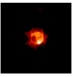
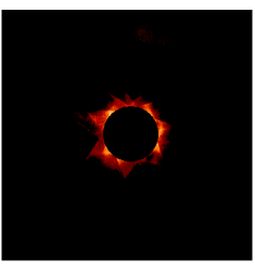
With Monte Carlo techniques, and accounting for the divergence of the beam as well as the mosaicity of the crystals, the PSF, for an ideal lens with diffraction from perfectly aligned crystals, was derived. The comparison between the expected PSF and that obtained with the lens prototype is shown in Fig. 5 (right panel). The dark circular region shows the expected PSF.
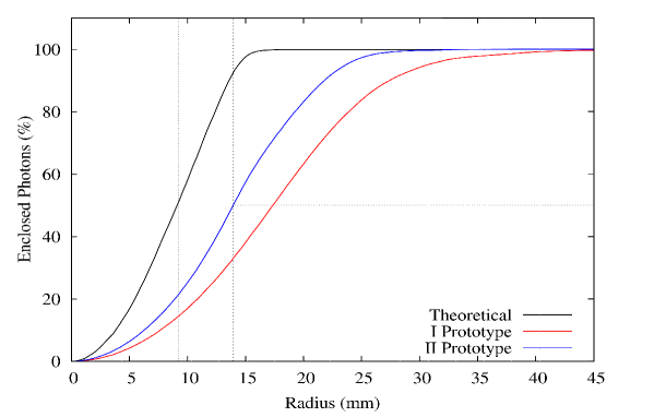
Instead Fig. 6 shows the cumulative distribution of the number of photons collected along the radial distance from the focal point. As can be seen, while the expected half power radius (HPR), i.e. the radius within which 50% photons are collected, is 9 mm, the measured HPR was 17.4 mm for the first prototype [4], and 13.9 mm for the second prototype. There is an improvement of 41.66 % with respect to the first prototype, considering theoretical value of the radius(9 mm) as the target. Thus this represents a significant improvement with respect to the first one. It can be also seen that, at the radius (16.00 mm) at which the saturation occurs for the expected cumulative distribution, the fraction of collected photons is around 0.7, with respect to the first prototype in which the fraction was less then .
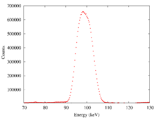
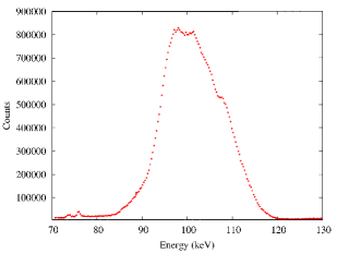
The spectral analysis of the focused beam was also performed and the results are presented in Fig. 7. The lens prototype was designed for giving a spectral peak at 100 keV at the focal point. In the left panel it is shown the spectrum obtained collecting only the photons coming in the central region of the focus, while in the right panel, it is shown the spectrum of all the photons reflected by the lens and collected on the focal plane. In both cases the exposure time was 1000 seconds. As can be seen, in the central region the peak is at 98.89 keV. The centroid of the spectrum of the central region achieves an intensity level 0.8 times that of the peak spectrum of all reflected photons.
Also a thorough spectral analysis was performed for each single crystal, in order to estimate the misalignment distribution in terms of centroid energy diffracted from each crystal tile. The results are reported in Table 1 in which, along with the peak energy and the FWHM of the spectrum diffracted by each crystal, the angular deviation of each crystal from the theoretical one is also evaluated.
| Crystal | Peak Energy | FWHM | Crystal | Peak Energy | FWHM | ||
|---|---|---|---|---|---|---|---|
| Number | (keV) | (keV) | (arcmin) | Number | (keV) | (keV) | (arcmin) |
| 1 | 102.31 | 6.53 | -3.54 | 13 | 96.88 | 5.39 | 2.08 |
| 2 | 98.37 | 5.01 | 0.53 | 14 | 103.70 | 6.83 | -4.99 |
| 3 | 101.47 | 5.65 | -2.67 | 16 | 104.66 | 6.15 | -5.99 |
| 4 | 104.45 | 7.13 | -5.76 | 17 | 103.92 | 5.94 | -5.22 |
| 5 | 97.09 | 4.50 | 1.87 | 18 | 105.27 | 6.15 | -6.62 |
| 6 | 99.29 | 5.31 | -0.41 | 20 | 99.79 | 6.67 | -0.93 |
| 8 | 103.10 | 6.33 | -4.36 | 21 | 103.81 | 5.17 | -5.10 |
| 9 | 104.49 | 6.31 | -5.81 | 23 | 104.52 | 7.50 | -5.84 |
| 11 | 96.42 | 5.12 | 2.53 | 27 | 94.12 | 6.78 | 4.95 |
| 12 | 98.60 | 5.33 | 0.29 | 28 | 95.27 | 7.08 | 3.76 |
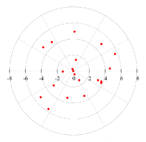
By shielding all the lens crystals but one, and measuring the barycenter coordinate of each diffracted spot, also the angular misalignment was determined for each lens crystal. Figure 8 shows the deviation occured for each crystal, from their expected perfect position. For the total set of tiles, this deviation is within 6 arcmin (for the first prototype it was 15 arcmin).
6 Discussion
We have presented the performance of a focusing lens made of 20 crystals, assembled by in the LARIX facility of the University of Ferrara.
Compared to the first prototype, we have increased the performance in terms of imaging capability. The maximum angular deviation of the crystal tiles from their nominal ones has been decreased from 15 arcmin to 6 arcmin.
The contribution of each step to the overall error budget has been evaluated. The alignment of the lattice planes with the gamma-ray beam axis has been performed with a precision better than 30 arcsec. The pin-holder alignment with the beam axis has been estimated to show a similar precision. The holes of the pin-holder are drilled parallel to the beam axis with an uncertainty of less than 20 arcsec. The same tolerance is in the direction of the counter-mask holes. Considering the 6 arcmin of mismatch between real and expected positioning of the crystals, we attribute this mismatch mainly to the mechanical insertion of the pins in the counter-mask and to the successive separation process of the entire lens from the counter-mask.
In order to improve further the lens PSF, the only way we see is that of adopting a different assembling technique, in which each crystal tile is directly glued on the lens frame under a gamma-ray beam control. This is the goal of the LAUE project supported by the Italian Space Agency ASI, which is on the way for the production of a lens petal prototype with 20 m focal length with an accuracy in the crystal orientation better than 10 arcsec [1].
Acknowledgements.
The authors wish to thank C. Guidorzi for his useful comments and discussions. We acknowledge the financial support by the Italian Space Agency (ASI) and also the contribution by the Italian Institute of Astrophysics (INAF). The design study was possible thanks to the 2002 Descartes Prize of the European Committee awarded to one of us (F. Frontera).References
- [1] Frontera, F. and Ballmoos, P. V., “Laue gamma-ray lenses for space astrophysics: status and prospects,” astro-ph.IM (2011).
- [2] Barriere, N. M., Rousselle, J., von Ballmoos, P., Abrosimov, N. V., Courtois, P., Bastie, P., Camus, T., Jentschel, M., Curlov, V. N., Natalucci, L., Roudil, G., Brejnholt, N. F., and Serre, D., “Experimental and theoretical study of diffraction properties of various crystalls for the realization of a soft–gamma ray laue lens,” Journal of Applied Crystallography (2009).
- [3] Zachariasen, W. H., [Theory of X-ray Diffraction in Crystals ], Wiley (1945).
- [4] Frontera, F., Loffredo, G., Pisa, A., Nobili, F., Carassiti, V., Evangelisti, F., Landi, L., Squerzanti, S., Caroli, E., Stephen, J. B., Anderson, K. H., Courtois, P., Auricchio, N., Milani, L., and Negri, B., “Focusing of gamma-rays with laue lenses: first results,” in [Society of Photo-Optical Instrumentation Engineers (SPIE) Conference Series ], 7011, SPIE (2008).
- [5] Loffredo, G., Frontera, F., Pellicciotta, D., Pisa, A., Carassiti, V., Chiozzi, S., Evangelisti, F., Landi, L., Melchiorri, M., and Squerzanti, S., “The ferrara hard x-ray facility for testing/calibrating hard x-ray focusing telescopes,” Experimental Astronomy 20, 413–420 (Dec. 2005).
- [6] Ferrari, F., Frontera, F., Loffredo, G., Virgilli, E., Guidorzi, C., Carassiti, V., Evangelisti, F., Landi, L., Chiozzi, S., Squerzanti, S., Caroli, E., Stephen, J. B., Shiavonne, F., Basili, A., Andersen, K. H., and Courtois, P., “New results on focusing of gamma rays with laue lenses,” in [Optics for EUV, X-Ray, and Gamma-Ray Astronomy III ], Proceedings of the SPIE 7437-19, Presented at the Society of Photo-Optical Instrumentation Engineers (SPIE) Conference (2009).