Technical Report \dbTitleHand Tracking based on Hierarchical Clustering of Range Data \dbAuthorRoberto Cespi, Andreas Kolb, Marvin Lindner \dbVersionMarch 14, 2024 \dbDisclosure0
Abstract
Fast and robust hand segmentation and tracking is an essential basis for gesture recognition and thus an important component for contact-less human-computer interaction (HCI). Hand gesture recognition based on 2D video data has been intensively investigated. However, in practical scenarios purely intensity based approaches suffer from uncontrollable environmental conditions like cluttered background colors.
In this paper we present a real-time hand segmentation and tracking algorithm using Time-of-Flight (ToF) range cameras and intensity data. The intensity and range information is fused into one pixel value, representing its combined intensity-depth homogeneity. The scene is hierarchically clustered using a GPU based parallel merging algorithm, allowing a robust identification of both hands even for inhomogeneous backgrounds. After the detection, both hands are tracked on the CPU. Our tracking algorithm can cope with the situation that one hand is temporarily covered by the other hand.
1 Introduction
Gesture-based real-time human-computer interaction requires a fast and robust segmentation of the human hands [13]. Classical approaches are based on 2D intensity or color images. However, this kind of techniques suffers from low efficiency and the lack of robustness in case of cluttered scenes or if applied under varying lighting conditions. Addressing practical application scenarios, techniques capable of handling both effects are strongly required; frequently applied simplifications, e.g. restricted lighting or material conditions [9], or marker- or glove-based approaches [16] are hardly applicable.
One major approach to overcome the problems of segmenting intensity or color image sequences for gesture recognition purposes is to use additional depth information, delivered by laser range systems [7], stereo cameras [11] or structured light range acquisition systems [12]. The major drawback of all these approaches is the comparably expensive sensing hardware and the significant space requirement, which is due to systematic constraints, e.g. the baseline required for stereo techniques or structured light, or mechanical setups in case of laser range scanners.
Recently, the Time-of-Flight (ToF) technology, based on measuring the time that light emitted by an illumination unit requires to travel to an object and back to a detector, has been manufactured as highly integrated ToF cameras. Unlike the other 3D acquisition systems, ToF cameras are very compact. ToF-cameras are realized in standard CMOS or CCD technology and thus can be cost efficiently manufactured [10, 20]. ToF-cameras have been successfully applied in the context of man-machine interaction, e.g. for facial tracking [6], for touch-free navigation in 3D medical applications [15], upper-body-gesture [8] and hand-gesture recognition [4].
In this paper, we introduce a hand segmentation approach based on a hierarchical clustering technique. Using hierarchical clustering is beneficial, since the final number of clusters of the scene delivering the “best” hand segmentations highly depends on the scene complexity and thus can not be determined beforehand. To achieve a high performance, we adopt the GPU-based clustering approach introduced by Chiosa and Kolb [3] to cluster fused range-intensity images. In this context, we introduce a novel homogeneity criterion for range-intensity images. Our hand segmentation and tracking system is capable of robustly detecting and tracking both hands, even under the condition one hand is temporarily covered by the other hand or in case a distructing object, e.g. a third hand appears.
The reminder of the paper is structured as follows. In Sec. 2 we discuss major prior work on segmentation and tracking techniques. Sec. 3 gives an overview on our hand tracking system, followed by detailed discussions on the applied hierarchical clustering method (Sec.4) and the hand tracking (Sec. 5). Sec. 6 presents some experimental results of our tracking approach and in Sec. 7 we draw some final conclusions.
2 Related Work
2.1 Segmentation
The most important basis for a hand tracking system is a robust and fast clustering algorithm in order to segment the hands from their environment. The Graph Cut algorithms, or Graph-based clustering algorithms [1], used by Schoenberg et al. [14], delivers good clustering results. However, with a runtime of approximately 3-4 FPS (frames per second) for a pixel sized image, this method is unsuitable for real-time applications. Another, simpler approach is used by Breuer et al. [2], where only the depth information is used to segment one hand from the background. By depth keying the background, only the nearest 3D point cloud will be detected as hand. This method however is too inflexible because the hand is restricted to a certain spatial position. Furthermore a hand segmentation based on range data only is too error-prone. Holte et al. [8] present a motion detection approach, where only the moving arms are segmented. In order to extract the moving arms Holte et al.used 3D double difference images and represent this data by their shape context scheme. Tsap [17] and Tsap and Shin [18] use a connected component analysis of skin-colored pixels, to segment the hands and the face. Only clusters with a certain shape will be selected as possible hand clusters. In [5] Ghobadi et al.propose a segmentation technique which combines two clustering approaches to cluster fused range intensity images: k-means and expectation maximization. The drawback of this method is the necessity to decide on the number of clusters beforehand.
2.2 Tracking
Tsap and Shin [18] use a simple depth analysis to distinguish the hand from the face, defining the skin colored cluster nearest to the camera as the hand. Furthermore they limit the depth space search for the hand dynamically by using the motion history of the last frames. In [17], Tsap tracks only non-static skin-colored objects by applying a set of filters on color, motion, and range data. After segmentation, Breuer et al. [2] apply a two-stage approach to detect the hand based on principal component analysis and a refinement based on a model-fitting in object space. Holte et al. [8] use the shape context (see Sec. 2.1) of the segmented moving arms for gesture recognition. A gesture is recognized by matching the current harmonic shape context with a known set, one for each possible gesture. Haker et al. [6] use a simple classifier to detect the human nose in fused intensity-range images for facial tracking. Soutschek et al. [15] use an approach to detect the hand as the closest object with regard to the ToF-camera. They combine thresholding applied to depth and amplitude information and an explicit palm detection in order to remove the forearm geometry. In [4], Ghobadi et al.apply their k-means clustering technique proposed in [5] to interactively track the hand on a frame-to-frame basis using haar-like features in combination with AdaBoost.
3 System Overview

The clustering and hand tracking algorithm is shown in Fig. 1. Summarizing the procedure, our system consists of the two major components, the hierarchical clustering and the tracking component.
Hierarchical Clustering
After receiving the range and intensity information from the camera, the GPU based parallel merging algorithm clusters the fused range-intensity data into regions (see Sec. 4.1). The algorithm searches the mutual, optimal merge partner for every region according to some homogeneity criterion. If this is the case, both regions will be merged into one and the region size and data will be updated. The clustering stops, when there are no optimal merge partners left (see Sec. 4.2).
Tracking
The tracking algorithm analyzes the clustering result. If the system is still in the initialization phase, the two clusters nearest to the camera, which have a given minimum size, will be assigned as the first hand and the second hand (see Sec. 5.1). After the initialization, from the current set of clusters two new hand clusters are chosen by comparing their homogeneity values to the hand-clusters from the last frame. The hands are assigned trough a nearest neighbor method (see Sec. 5.2). If only one cluster was found, we assume that one hand is covered by the other, the lost hand will be marked. The lost hand will be searched in the subsequent frames and will only be marked as found, if a cluster satisfies specific homogeneity and space criteria (see Sec. 5.3).
4 Segmentation (Clustering)
A hierarchical clustering algorithm, implemented on the GPU as a parallel merging algorithm, is used in order to segment the hands from their environment. The advantage of a hierarchical approach is based on the fact, that the number of clusters, and thus the size and shape of the hand clusters, results only from the applied homogeneity criterion. This means that no predefined number is necessary.
The parallel clustering method (see Sec. 4.1), as well as the merging criterion (see Sec. 4.2) which is used to merge pixels and clusters into new clusters, are discussed in the following subsections.
4.1 Parallel Merging Algorithm
The Parallel Merging Algorithm is a hierarchical clustering method [19], where initially each pixel represents a region (cluster) with his own region-ID and region characteristics.
For merging two regions , they have to satisfy a given boolean criterion based on a homogeneity descriptor consisting of components, i.e.
| (1) |
Based on the the individual homogeneity components , the homogeneity difference between two regions is deduced
| (2) |
where is the weight of the individual homogeneity components.
Given a specific cluster , all neighboring clusters that satisfy the homogeneity criterion are identified and the optimal merge partner is selected, i.e.
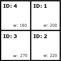
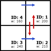
After identifying the optimal merge partner for , both regions will be merged into a single region and the homogeneity measure for the merged region is determined. The new merged region gets the greater region ID of both merge partners and its characteristics will be updated. However, with a sequential merging algorithm, the merging result depends on the merging order (see Fig. 2). A better solution is therefore to check for all regions its optimal merge partner. Two regions are merged only if the optimal merge partner choice is mutual, i.e. if .
The merging of regions is performed in parallel and thus the following rules must be obeyed in order to obtain a correct result [19]:
-
1.
Each region can only merge with one other region at a time; that being the neighbor which best satisfies the merging criteria.
-
2.
In case of an equal measure the neighbor with the larger ID is selected in order to prevent cyclic dependencies.
-
3.
A merge choice must be mutual in order for two regions to merge.
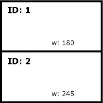
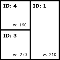
These rules restrict a region to only merge with a single neighbor during any merging iteration. The resulting region could otherwise be in violation of the homogeneity requirements (see Fig. 3). By giving the new region the greater ID (in combination with rule number 2), possible deadlocks can be avoided. After merging two regions into a single region, its characteristics will be updated.
A region that was unable to merge during a given iteration because its selection was not mutual, may succeed in a subsequent iteration (see Fig. 3).
This iteration will be repeated until there is no optimal merge partner for any region left, i.e. until all pairs of neighbors violate the merge criterion (see Eq. (1)).
4.2 Merging Criterion
The merging criterion, which is used to check the homogeneity between neighboring regions is based on fusing intensity and range information into a single value, similar to Ghobadi et al. [5]. The choosen homogeneity descriptor (s. Sec. 4.1) which characterizes a region consists of two components:
| (3) |
where denotes the average -distance of the region with regard to the camera’s optical axis and the fused intensity and range value.
The characterizing entities for each region , i.e. initially a single pixel, are given by the distance in spherical sensor coordinates and the reflected active light of a region/pixel.
As the desired needs to represent homogeneous characteristics of a pixel region in a robust way, we apply the well known dependency rule between intensity and the distance to derive a robust measure:
| (4) |
Thus, is a nearly constant measure for every individual surface and interpreting each -pair as point in the Euclidean plain, we derive as follows:
| (5) |
When merging regions, the mean average of both regions and will be used for the new region’s homogeneity descriptor. The values of the thresholds ( and ) for the merging criterion, as well the weights ( and ) needed for the homogeneity difference, are listed in Table 1.
The hierarchical merging is applied to each frame delivered by the ToF-camera. The algorithm is realized using a GPU-implementation similar to Chiosa and Kolb [3], which has be introduced for mesh and data clustering. We simply use a standard 4-neighborhood-size to define pixel neighbors and integrate our homogeneity measure as the merge criterion.
5 Hand Tracking
The hand tracking algorithm has been implemented on the CPU and is divided into two steps. Step one is the initialization, where the hands will be identified. In step two, both hands will be tracked.
5.1 Initialization
In step one, the hands will be detected from the set of regions, that has been clustered until convergence, i.e. until no further pair of neighboring clusters fulfills the merge criterion (see Eq. (1)). The two clusters which will be identified as hands are determined by the following simple rules:
-
•
closest to the ToF-camera and
-
•
the cluster size is above a given threshold.
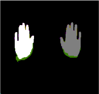
Both regions will be then assigned as first hand (cluster ) and second hand (cluster ). As long as these regions satisfy the mentioned criteria, both hands can be clearly assigned in the successive image through a nearest neighbor assignment (see Fig. 4).
After 30 frames, the initialization stops and the tracking is initiated. The following information of the hand clusters will be preserved from the initialization:
-
•
and : Region IDs of both hand clusters,
-
•
and : Homogeneity measure of both hand clusters,
-
•
and : Cluster center of the first and the second hand in 3D, with regard to the camera’s optical center.
All these values are required in the tracking phase.
5.2 Frame-to-Frame Tracking
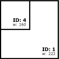
In step two, the maximum and minimum camera range will be limited to the hands (see Fig. 5). Thus, pixels outside the range will be ignored for clustering, resulting in a speed up for the clustering process.
and are recalculated for every frame as follows:
where are the average distances of the first and the second hand and a distance threshold. is needed, so that the user can move his hands freely back and forth and avoids, that the hands could be clipped away in the next frame (see Fig. 6).
After setting the minimum and maximum range, two new hand clusters will be searched in the next frame. All the clusters whose size are above a given minimum size , will be compared to the hand clusters from the last frame, based on their homogeneity measure . From the set of possible hand clusters, two clusters will be then assigned as the new hands through a nearest neighbor method with regard to the tracking information ) from the hand clusters identified in the last frame.
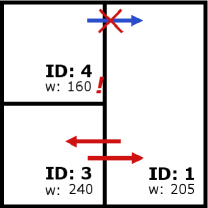
5.3 Mutual Occlusion of Hands
The tracking method described in Sec. 5.2 works robustly as long as two hands are clearly visible and distinguishable in the ToF-images. Crossing hands would, however, lead to problems, because one hand would be temporarily covered by the other hand, but the tracking algorithm would still search for the second hand.
Therefore, to allow that one hand temporary gets covered by the other hand, the following control method has been added to the tracking algorithm.
Right after the hands have been detected in the initialisation step (see Sec. 5.1), the algorithm checks the -distance between both hands in every frame. Depending on this distance it will be decided if both hands are in a critical area , where the possibility of covering one hand with the other hand in one of the subsequent frames is high. is defined as follows:
where is the -position of the -th hand and is the minimal distance.
As long as the distance between both hands is above the threshold , the hands will be tracked as described in Sec. 5.2). In case if , the following procedure is initiated:
Check for possible disappearance of a single hand
A hand is considered missing, if in the current frame:
-
•
no cluster has been found which can resemble the hand (based on ), or
-
•
a cluster has been found, but the distance between its cluster center and the hand position of the last frame, is above a given maximal distance, implying that no cluster can be assigned to the hand in a meaningful way.
Detection and tracking of the uncovered hand
After a hand gets covered by the other, the last resolved tracking information of the disappeared hand cluster (backhand cluster ) is stored in order to detect the lost hand again after reappearance. The front hand cluster , however, will be continuously tracked as described in Sec. 5.2. The lost hand will be searched in the set of remaining clusters. In order to reassign the lost hand to a cluster the following criteria have to be satisfied:
-
•
The cluster center must be behind the front hand cluster center, in -direction, i.e. .
-
•
The distance between the cluster center and the center of the front hand cluster , must not exceed a threshold :
Thus the lost hand appears beside the hiding hand.
-
•
The difference between the homogeneity measures of the cluster and the stored measure of the back hand cluster , must not exceed a threshold : .
If more than one cluster satisfy these criteria, the new uncovered hand cluster will be assigned to the one with minimal deviation. If none of the clusters satisfy these criteria, the search for the lost hand will continue in the next frame.
6 Results
| Parameters | Value |
|---|---|
| (rad) | |
| (rad) | |
| Process | time (Init) | time (Tracking) |
|---|---|---|
| Update Camera | 16 | 16 |
| Find Mergepartner | 29 | 27 |
| Merge Regions | 5 | 3 |
| Update Values | 10 | 4 |
| Tracking | 7 | 9 |
| Total Time | 67 | 59 |
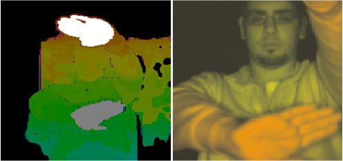
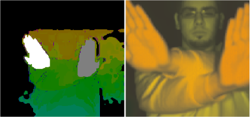
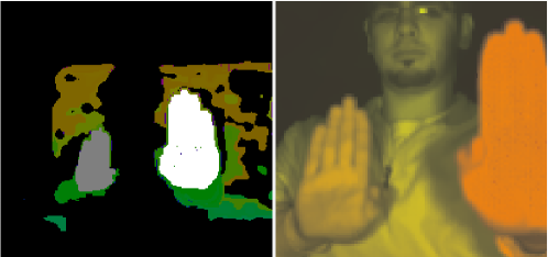
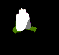
After both hands have been detected in the initialization, the clustering and tracking algorithm runs with an average frame-rate of 16 frames/sec (see Table 2). However, some restrictions must be satisfied, to ensure a flawless hand tracking. Objects or bodyparts, with a similar reflectivity as skin must not get in contact with a hand, i.e. touch the hand in approximately the same -distance to the ToF-camera, otherwise they will be assigned to one hand cluster (see Fig. 7).
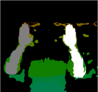
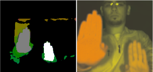
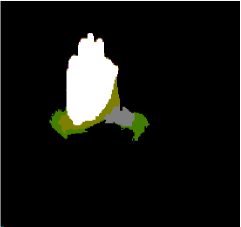
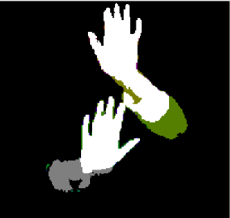
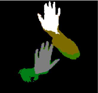
A similar error occurs when crossing both hands. Being the fact, that both hands usually have the exact same homogeneity measure , not keeping a given minimum distance in -direction while crossing, can lead to a merging of both hands into a single hand cluster (see Fig. 8). These clustering issues can forthermore lead to tracking errors (see Fig. 8).
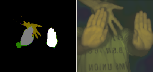
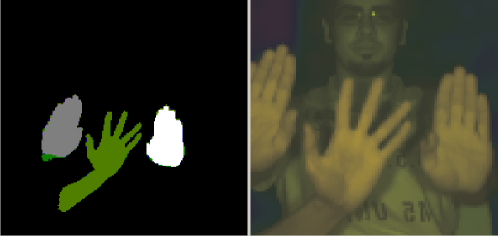
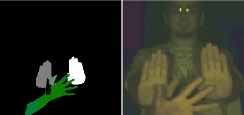
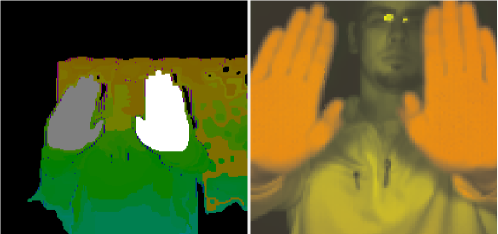
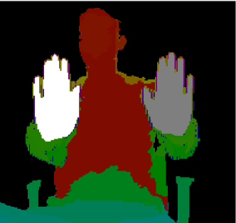
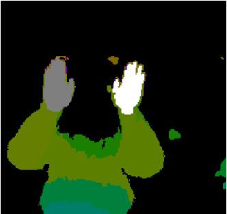
However, as long as the mentioned restrictions are satisfied, the tracking algorithm can handle a third hand and will always track the correct two visible hands (see Fig. 9).
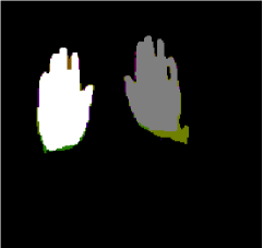
As mentioned in Sec. 4.2, the homogeneity measure is based on the idea of Ghobadi et al. [5]. The main difference between both measures is, that Ghobadi et al.chose a linear approach to describe the relation between distance and intensity of a given cluster :
| (6) |
where is the normalized distance and the normalized
intensity of the cluster. This approach can lead to inacurate clustering
results (see Fig. 10). With a more accurated calculation of
from Eq. (5) those clustering errors are significantly reduced.
A list with all the parameters and their values, which were applied, are shown in Table 1.
7 Conclusion
In this paper, we introduce a fast an robust hand segmentation approach based on a hierarchical clustering technique, which is implemented on the GPU as a parallel merging algorithm in order to achieve a high performance. We also introduce a novel homogeneity criterion robustly merging regions in fused range-intensity images. The intensity and range information is fused into one pixel value, representing its combined intensity-depth homogeneity.
The results show that when certain restrictions are satisfied, our hand segmentation and tracking system is capable of robustly detecting and tracking both hands in real-time, even under the condition that one hand is temporarly covered by the other hand.
References
- [1] Y. Boykov, O. Veksler, and R. Zabih. Fast approximate energy minimization via graph cuts. IEEE Trans. Pattern Anal. and Mach. Intell., 23(11):1222–1239, 2001.
- [2] P. Breuer, C. Eckes, and S. Müller. Hand gesture recognition with a novel IR time-of-flight range camera – a pilot study. In Computer Vision / Computer Graphics Collaboration Techniques and Applications (MIRAGE), 2007.
- [3] I. Chiosa and A. Kolb. GPU-based multilevel clustering. IEEE Trans. on Visualization and Computer Graphics, 17(2):132–144, 2011.
- [4] S. Ghobadi, O. Loepprich, F. Ahmadov, J. Bernshausen, K. Hartmann, and O. Loffeld. Real time hand based robot control using 2D/3D images. In Proc. Int. Symp. Visual Computing (ISVC), volume 5359 of LNCS, pages 307–316. Springer, 2008.
- [5] S. E. Ghobadi, O. E. Loepprich, K. Hartmann, and O. Loffeld. Hand segmentation using 2D/3D images. In Proc. of Image and Vision Computing New Zealand, pages 64–69, Dezember 2007.
- [6] M. Haker, M. Böhme, T. Martinetz, and E. Barth. Geometric invariants for facial feature tracking with 3D TOF cameras. In Proc. IEEE Sym. on Signals Circuits & Systems (ISSCS), pages 109–112, 2007.
- [7] B. Heisele and W. Ritter. Segmentation of range and intensity image sequences by clustering. Proc. Int. Conf. on Information, Intelligence, and Systems, page 223, 1999.
- [8] M. Holte, T. Moeslund, and P. Fihl. View invariant gesture recognition using the CSEM SwissRanger SR-2 camera. Int. J. of Intelligent Systems Technologies and Applications, 5:295 – 303, 2008.
- [9] C. Keskin, O. Aran, and L. Akarun. Real time gestural interface for generic applications. In Proc. European Signal Processing Conference (EUSIPCO), 2005.
- [10] A. Kolb, E. Barth, R. Koch, and R. Larsen. Time-of-Flight cameras in computer graphics. J. Computer Graphics Forum, 29(1):141–159, 2010.
- [11] D.-H. Lee and K.-S. Hong. Game interface using hand gesture recognition. In Proc. Int. Conf. Computer Sciences and Convergence Information Technology (ICCIT), pages 1092–1097, 2010.
- [12] S. Malassiotis, F. Tsalakanidou, N. Mavridis, V. Giagourta, N. Grammalidis, and M. Strintzis. A face and gesture recognition system based on an active stereo sensor. In Proc. Int. Conf. Image Processing, volume 3, pages 955–958, 2001.
- [13] S. Mitra and T. Acharya. Gesture recognition: A survey. IEEE Trans. on Systems, Man, and Cybernetics, 37(3):311 –324, 2007.
- [14] J. R. Schoenberg, A. Nathan, and M. Campbell. Segmentation of dense range information in complex urban scenes. In Proc. IEEE/RSJ Int. Conf. on Intelligent Robots and Systems, pages 2033 – 2038, 2010.
- [15] S. Soutschek, J. Penne, and J. Hornegger. 3D gesture-based scene navigation in medical imaging applications using time-of-flight cameras. In Proc. IEEE Conf. on Computer Vision & Pattern Recogn.; Workshop on ToF-Camera based Computer Vision, 2008. DOI 10.1109/CVPRW.2008.4563162.
- [16] T. Starner, J. Weaver, and A. Pentland. Real-time American sign language recognition using desk and wearable computer based video. IEEE Trans. on Pattern Analysis and Machine Intelligence, 20(12):1371 –1375, 1998.
- [17] L. V. Tsap. Gesture-tracking in real time with dynamic regional range computation. Real-Time Imaging, 8:115–126, 2002.
- [18] L. V. Tsap and M. C. Shin. Dynamic disparity adjustment and histogram-based filtering of range data for fast 3-d hand tracking. Digital Signal Processing, 14(6):550–565, 2004.
- [19] M. Willbeek-LeMair and A. P. Reeves. Region growing on a hypercube multiprocessor. In C3P Proceedings of the third conference on Hypercube concurrent computers and applications, volume 2, pages 1033–1042. ACM, 1989.
- [20] Z. Xu, R. Schwarte, H. Heinol, B. Buxbaum, and T. Ringbeck. Smart pixel – photonic mixer device (PMD). In Proc. Int. Conf. on Mechatron. & Machine Vision, pages 259–264, 1998.