Air Entrainment by Viscous Contact Lines
Abstract
The entrainment of air by advancing contact lines is studied by plunging a solid plate into a very viscous liquid. Above a threshold velocity, we observe the formation of an extended air film, typically microns thick, which subsequently decays into air bubbles. Exploring a large range of viscous liquids, we find an unexpectedly weak dependence of entrainment speed on liquid viscosity, pointing towards a crucial role of the flow inside the air film. This induces a striking asymmetry between wetting and dewetting: while the breakup of the air film strongly resembles the dewetting of a liquid film, the wetting speeds are larger by orders of magnitude.
Objects that impact on a liquid interface can entrain small bubbles of air into the liquid. This happens for example when raindrops fall in the ocean Oguz et al. (1995) or when liquid is poured into a reservoir at sufficiently large speeds Eggers (2001); Lorenceau et al. (2004). Such entrainment of air is often a limiting factor in industrial applications such as coating and nano-scale printing techniques, where the bubbles disturb the process Blake and Ruschak (1979); der Jong et al. (2006). A well studied case is the entrainment of air by very viscous jets impacting on a reservoir of the same liquid Joseph et al. (1991); Jeong and Moffatt (1992); Eggers (2001); Lorenceau et al. (2004). The onset of entrainment is essentially determined by the properties of the liquid, , which reflects a balance of the liquid viscosity and the surface tension . Changing the nature of the gas only has a minor influence on the entrainment process Eggers (2001); Lorenceau et al. (2004).
A very different picture has emerged recently in the context of drops impacting on a wall, for which the presence of air has a dramatic effect Xu et al. (2005); Driscoll et al. (2010); Tsai et al. (2010). It was found that splashing can be suppressed completely by reducing the air pressure to about a third of the atmospheric pressure. This caused huge excitement, in particular because such a pressure reduction does not lead to any change of the gas viscosity Josserand et al. (2010); Mandre et al. (2009); Mani et al. (2010): pressure only affects the gas density, and thus the speed of sound and the mean free path in the gas. A similar paradox is encountered for air entrainment by rapidly advancing contact lines, where a liquid advances over a surface that it partially wets Duez et al. (2007); Ledesma-Aguilar et al. (2011); Blake and Ruschak (1979); Burley and Kennedy (1976a); Simpkins and Kuck (2000); Benkreira and Khan (2008). Once again, it was found that depressurizing the gas leads to a significant increase of the threshold of air entrainment Benkreira and Khan (2008); Benkreira and Ikin (2010). This contradicts the classical viewpoint that, for given wettability, the contact line speed depends mainly on the liquid properties as Cox (1986); Snoeijer et al. (2006); Duez et al. (2007); Bonn et al. (2009), with minor influence of the gaseous phase.
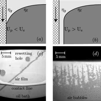
In this Letter we reveal the role of the air for advancing contact lines in a paradigmatic system: a partially wetting solid plate is plunged into a reservoir of viscous liquid (Fig. 1). At sufficiently high speeds we observe the entrainment of an air film, typically microns thickness, which subsequently decays into bubbles. The liquid viscosity is varied over more than two decades by using silicon oils of different molecular weights. It is found that the entrainment speed changes much less than the expected scaling . Using an approximate hydrodynamic model we argue that this can be attributed to the flow of air into the strongly confined film, making the contact line velocity strongly dependent on both gas and liquid viscosities. This induces a striking asymmetry between wetting and dewetting: the same liquid can advance much faster than it recedes, by orders of magnitude.
The experiments are carried using silicon oils (PDMS, Rhodorsil 47V series) with dynamic viscosities and Pa.s. These liquids are essentially non-volatile, insensitive to contamination, while the surface tension and density are approximately constant for all viscosities. The reservoir is a transparent acrylic container of size is xxcm, which is much larger than the capillary length mm. The substrate consists of a silicon wafer (circular, diameter cm), which is coated by a thin layer of fluorinated material (FC 725 (3M) in ethyl acetate). For all liquids, this results into static contact angles between and . The wafer is clamped onto a mm thick metallic blade screwed to a cm long high-speed linear stage. The combination of using controlled speeds and very viscous liquids one avoids complexities of splashing as well as the formation of interface cusps Blake and Ruschak (1979); Burley and Kennedy (1976a); Duez et al. (2007); Simpkins and Kuck (2000); Benkreira and Khan (2008). In addition the effect of inertia is eliminated both in the gas and in the liquid; the relevant Reynolds numbers are at worst , but typically orders of magnitude smaller. For each liquid, we plunge the wafer into the reservoir at different plate velocities , up to m/s. The process is recorded using a high-speed Photron SA3 camera (Hz, xpixels). The plate and contact line velocities are then extracted from space-time diagrams using a correlation technique with a sub-pixel resolution, leading to a precision better than the percent. Reproductibility is achieved within . The film thickness is determined from an accurate measurement of the volume of air entrained in the bath. The air bubbles trapped at the end of an experiment are imaged with Nikon D300s (x pix) mounted with macro-lens. The size of each bubble is determined automatically within a m resolution, by fitting an elliptic shape. Most of the uncertainty on results from the estimate of the surface covered by the air film.
The experimental scenario is presented in Fig. 1. At small speeds we observe that the contact line equilibrates to form a stationary meniscus and no air is entrained into the liquid (Fig. 1a). Above a critical velocity, however, the contact line keeps moving downward into the reservoir and deposits a thin film of air (Fig. 1b). Subsequently, the air film breaks up into small air bubbles. The dynamical structures that appear during the breakup of the film turn out to depend strongly on the oil viscosity, as can be seen from the experimental images of Fig. 1cd. For the most viscous liquids the air films are very fragile and rapidly break up into smaller bubbles (Fig. 1d). However, for the lower viscosities one observes the formation of very extended air films (Fig. 1c). At the front of the film, the contact line develops a ridge-like structure that is common for dewetting of liquid films Redon et al. (1991); Flitton and King (2004); Snoeijer and Eggers (2010). The peculiarity of the present experiment is that in this case the air is dewetted, not the liquid.
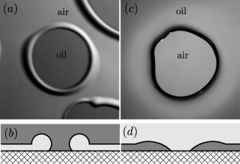
An even more striking analogy with classical dewetting of liquids is the nucleation of nearly circular regions inside the film (Fig. 1c). However, the circles now represent regions of rewetting, where the liquid reestablishes the contact with the solid. These “rewetting holes” can be considered as the inverse of the “dewetting holes”, since the roles of air and liquid are exchanged. Figure 2a shows a close-up of a rewetting hole (cross-section sketched in Fig. 2b). The radius of the holes increases linearly with time, and the advancing contact lines collects the air inside a thick rim. While this is analogous to the inverse problem of the dewetting holes (Fig. 2cd), the process is by no means symmetric: the rewetting holes grow with a velocity that is orders of magnitude faster than their dewetting counterparts, up to a factor for the liquids used in this study.
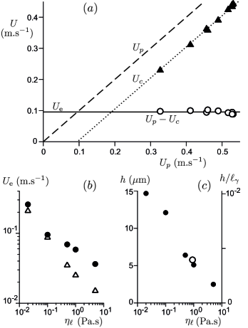
We further quantify the velocity of air entrainment for different liquid viscosities. A first measurement of is obtained from the growth velocities of the rewetting holes as in Fig. 2. A second entrainment velocity can be extracted by a selecting a central part of the front of the air film, for which we obtain the contact line velocity in the frame of the liquid reservoir. Figure 3a reports the measured values for Pa.s, showing that the contact line velocity increases linearly with plate velocity . Interestingly, however, the relative velocity, , turns out to be independent of the plate velocity and therefore seems to be an intrinsic property of the advancing contact line. This is why we may consider the growth velocity of the rewetting holes to be an independent measurement of the entrainment velocity. The resulting entrainment velocities are shown in Fig. 3b, as a function of liquid viscosity . Indeed, the two experimental definitions of agree very well for the smallest (closed circles are based on the front of the film, open triangles correspond to rewetting holes). For larger , the film rapidly destabilizes and it is more difficult to define the front of the film. This induces a difference between the two types of velocity measurements of about a factor 2; the hole velocities are certainly more reproducible in this very viscous regime.
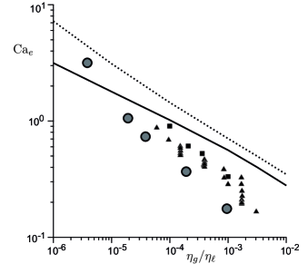
The key result of the velocity measurements is that, although decreases with liquid viscosity, the dependence is clearly much weaker than the expected . The entrainment speed is reduced by a factor , while viscosity is varied by a factor 250 (Fig. 3b). Since the liquid inertia is negligible for these highly viscous liquids, this means that the properties of the air must have a significant influence on the entrainment speed. On the other hand, the speed is not determined by the air alone, since that would yield no dependence on at all. To reveal the interplay between air and liquid phases, we introduce a dimensionless capillary number, , that is based on the liquid viscosity. The experimental results are represented in Fig. 4, showing versus the ratio of gas and liquid viscosities (closed circles). Clearly, the capillary number for air entrainment displays a dependence that is much stronger than , which is the scaling for air entrainment by liquid jets Eggers (2001); Lorenceau et al. (2004) and the prediction by Ref. Cox (1986). The air thus has a much larger influence than expected. On the same figure we collected data from the coating literature, based on tapes running continuously in a bath, showing a similar trend (various symbols, see caption). Note that in these experiments the contact line typically develops a sharp cusp from which small air bubbles are emitted, rather than an extended air film.
In order to understand the influence of air, one can extend the common lubrication approximation to large slopes and 2 phase flow, but small curvature of the interface. In the spirit of Snoeijer (2006); Hewson (2009), one can start from the analytical solutions of flow in a wedge due to Huh & Scriven Huh and Scriven (1971), as detailed in the Supplementary Material sup (2011). Numerical solution of the model provides the provides the capillary number for entrainment shown in Fig. 4 as the solid line. This captures the order of magnitude for the entrainment speed as well as the unexpectedly strong dependence on viscosity ratio. However, due to the strong curvature of the interface, the approximation cannot be expected to give a fully quantitative prediction. Within this model, the viscous dissipation rates, and in the gas and the liquid can be estimated as a function of the local slope :
| (1) |
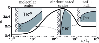
which is slightly different from the estimates in Duez et al. (2007); Ledesma-Aguilar et al. (2011). Clearly, the dissipation in the gas can dominate over liquid dissipation for contact angles very close to , with a cross-over occurring when . As shown in Fig. 5, such angles indeed appear naturally when the liquid advances rapidly, while this is not the case when the liquid recedes. This explains the marked asymmetry between wetting and dewetting: the faster advancing speed is due to the reduction of dissipation near .
In this Letter we experimentally showed that the entrainment speeds of advancing contact lines do not scale as , but has a much weaker variation with liquid viscosity. We explain this by the influence of the air flow when the local angle of the interface is close to . Can such a scenario explain the observed increase of entrainment speed when depressurizing the air? A pressure reduction does not affect the gas viscosity, but it does increase the mean free path by a factor . Since the mean free path under ambient conditions is approximately nm, it is pushed well into the micron range when pressure is reduced by a factor Benkreira and Khan (2008); Benkreira and Ikin (2010). The mean free path then becomes comparable to the film thickness measured experimentally (Fig. 3c). Interpreting the mean free path of the gas as an effective slip sup (2011); Bocquet (1993), this indeed yields an increase of (dotted line in Fig. 4). This suggests that depressurized air acts as a Knudsen gas when confined close to the contact line.
Acknowledgements.
Acknowledgments – We are grateful to J. Eggers and K. Winkels for valuable discussions. M. Fruchart is thanked for his help during preliminary experiments. TSC acknowledges financial support by the FP7 Marie Curie Initial Training Network “Surface Physics for Advanced Manufacturing” project ITN 215723.References
- Oguz et al. (1995) H. N. Oguz, A. Prosperetti, and A. Kolaini, J. Fluid Mech. 294, 181 (1995).
- Eggers (2001) J. Eggers, Phys. Rev. Lett. 86, 4290 (2001).
- Lorenceau et al. (2004) E. Lorenceau, D. Quéré, and J. Eggers, Phys. Rev. Lett. 93, 254501 (2004).
- Blake and Ruschak (1979) T. D. Blake and K. J. Ruschak, Nature 282, 489 (1979).
- der Jong et al. (2006) J. der Jong, R. Jeurissen, H. Borel, M. van der Berg, H. Wijshoff, H. Reinten, M. Versluis, A. Prosperetti, and D. Lohse, Phys. Fluids 18, 121511 (2006).
- Joseph et al. (1991) D. D. Joseph, J. Nelson, M. Renardy, and Y. Renardy, J. Fluid Mech. 223, 383 (1991).
- Jeong and Moffatt (1992) J.-T. Jeong and H. K. Moffatt, J. Fluid Mech. 241, 1 (1992).
- Xu et al. (2005) L. Xu, W. W. Zhang, and S. R. Nagel, Phys. Rev. Lett. 94, 184505 (2005).
- Driscoll et al. (2010) M. M. Driscoll, C. C. Stevens, and S. R. Nagel, Phys. Rev. E 82, 036302 (2010).
- Tsai et al. (2010) P. Tsai, R. C. A. van der Veen, M. van de Raa, and D. Lohse, Langmuir 26, 16090 (2010).
- Josserand et al. (2010) C. Josserand, P. Ray, and S. Zaleski, 7th International Conference on Multiphase Flow (2010).
- Mandre et al. (2009) S. Mandre, M. Mani, and M. P. Brenner, Phys. Rev. Lett. 102, 134502 (2009).
- Mani et al. (2010) M. Mani, S. Mandre, and M. Brenner, J. Fluid Mech. 647, 163 (2010).
- Duez et al. (2007) C. Duez, C. Ybert, C. Clanet, and L. Bocquet, Nat. Phys. 3, 180 (2007).
- Ledesma-Aguilar et al. (2011) R. Ledesma-Aguilar, R. Nistal, A. Hernndez-Machado, and I. Pagonabarraga, Nature Materials 10, 367 (2011).
- Burley and Kennedy (1976a) R. Burley and B. S. Kennedy, Chem. Eng. Sci. 31, 901 (1976a).
- Simpkins and Kuck (2000) P. G. Simpkins and V. J. Kuck, Nature 403, 641 (2000).
- Benkreira and Khan (2008) H. Benkreira and M. I. Khan, Chem. Eng. Sci. 63, 448 (2008).
- Benkreira and Ikin (2010) H. Benkreira and J. B. Ikin, Chem. Eng. Sci. 65, 1790 (2010).
- Cox (1986) R. G. Cox, J. Fluid Mech. 168, 169 (1986).
- Snoeijer et al. (2006) J. H. Snoeijer, G. Delon, M. Fermigier, and B. Andreotti, Phys. Rev. Lett. 96, 174504 (2006).
- Bonn et al. (2009) D. Bonn, J. Eggers, J. Indekeu, J. Meunier, and E. Rolley, Rev. Mod. Phys. 81, 739 (2009).
- Redon et al. (1991) C. Redon, F. Brochard-Wyart, and F. Rondelez, Phys. Rev. Lett. 66, 715 (1991).
- Flitton and King (2004) J. C. Flitton and J. R. King, J. Engin. Math. 50, 241 (2004).
- Snoeijer and Eggers (2010) J. H. Snoeijer and J. Eggers, Phys. Rev. E 82, 056314 (2010).
- Burley and Kennedy (1976b) R. Burley and B. S. Kennedy, Brit. Polym. J. 8, 140 (1976b).
- sup (2011) See supplementary Material (2011).
- Snoeijer (2006) J. H. Snoeijer, Phys. Fluids 18, 021701 (2006).
- Hewson (2009) R. W. Hewson, J. Fluids Engineering 131, 041205 (2009).
- Huh and Scriven (1971) C. Huh and L. E. Scriven, J. Coll. Int. Sci. 35, 85 (1971).
- Bocquet (1993) L. Bocquet, C. R. Acad. Sci. Paris 316, serie 2, 7 (1993).