The methods to detect vacuum polarization by evanescent modes
Abstract
We propose the evanescent-mode-sensing methods to probe the electrodynamics (QED) vacuum polarization. From our methods, high-sensitivity can be achieved even though the external field is much smaller than the Schwinger critical field and may be realizable in contemporary experimental conditions. The methods are based on the effect of phase change and time delay of evanescent wave which is transmitted in QED vacuum. These methods can also be widely used in sensitive probing of tiny dissipation in other fields.
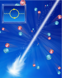
Vacuum is one of the most fundamental concepts in all quantum fields of high-energy physicsPerkins2000 , condensed-matter physicsAshcroft1976 , statistical opticsGoodman1985 , etc., since all excitations are from the vacuum and determined by vacuum properties in some way. Modern vacuum concept is started from quantum electrodynamics (QED), which describes the interaction between light and matter (including vacuum), and has been widely and continually studied both experimentally and theoreticallyFeynman1985 ; DingKaplanPRL1989 ; HeylJPA1996 ; RuffiniPR2009 ; GiesPRD2000 ; KingNP2010 . According to QED, the vacuum becomes weakly anisotropic, dispersive, dissipative and even nonlinear optical medium, when there is an external electric field and its strength is approaching the Schwinger critical value . In other words, the real and imaginary parts of vacuum refractive index could deviate from unit and zeroRuffiniPR2009 ; DingKaplanPRL1989 , respectively. Physically, the deviation of the imaginary part is mainly from the electron-positron pair generation. However, the electron-positron pair generation, also generally called as vacuum polarization (VP) processesRuffiniPR2009 , which is schematically shown in Fig.1, has not been directly observed for over half century.
VP processes are very important to understand basic quantum processes in many fields, e.g. in condensed matter physics where the “electron-hole” pair generation is widely used in calculating of electron self-energy and electron-phonon interactionAshcroft1976 . For QED vacuum, the obstacle to observe VP is the very high critical electric field which is beyond the contemporary technical limit. Therefore, it is natural to wonder if we can find an approach to probe VP with external field much smaller than .
On the other hand, evanescent electromagnetic wave is intensively studied recently because of its potential usage in the sensitive detectors and other directionsHunspergerSV1985 ; BarwickNature2009 ; CarnigliaJOSA1971 . In this work, we propose the evanescent-mode-sensing methods to detect the QED VP, which is based on the measuring the phase change and the time delay of evanescent waves in the vacuum. We find that the required external field could be one order weaker than , which may be realizable by contemporary experiments.
The idea of this work is from the thought of “dual roles” of real and imaginary parts of refractive index for the radiative waves or the evanescent waves. Supposing a medium with complex dielectric constant where and are extremely small, our goal is to detect the very tiny change of and . For radiative waves, determines the real part of wavevector , and we can easily measure the phase change or group delay to detect the change of . So, it is natural to choose the radiative wave as the probing light for measuring the index real part change, as what have been done in the experiments to detect the vacuum birefringence effect. On the other hand, for radiative waves, very tiny only causes an extremely small intensity decay, which is very hard to measure in the limited laboratory space. However, for the evanescent waves, the roles of and are totally exchanged, i.e., dominates the decay rate, while the tiny introduces a real part of wavevector in the decay direction and causes a phase change which is much easier to detect. Further more, we will demonstrate that the tiny imaginary part can also introduce the energy propagation whose energy velocity is extremely slow. Such a slow wave can be detected by measuring the delay time at a very short distance. The phase change and the time delay can be used for sensitive detecting, especially for the QED VP.
We would like to emphasize the mechanism difference between ours and that in the previous workCarnigliaJOSA1971 , which is based on the systems with at least “two interfaces” (such as a slab). Such “two-interfaces” structure will generate both evanescent modes and at the same time, and such two evanescent modes can carry electromagnetic energy currentLiuZiAPL2010 , which is the essence of “tunneling effect”. So, even the dissipation of material could be neglected (dissipation is truly neglected in that work), the propagation of electromagnetic energy is still available based on that tunneling mechanism. However, in our model, the mechanism is totally different, since there is only one single interface in our model (Fig.2, the details can be seen in the following). The obvious evidence is that, if without dissipation in our “single-interface” model, there will be no the energy current at all in the no-dissipation mediumJAKong1990 , then, the phase change is zero and the energy delay time makes no sense. But, we know there is tiny dissipation in the QED vacuum because of VP, so that the phase change and the energy delay time in our model are not from tunneling effect, but purely from QED vacuum dissipation.
Here we note that, because the probing light is much weaker than the external field in our study, the nonlinear effect is negligible. Since it is a linear problem, all dynamical processes, such as the propagation of envelope fluctuation of the transmitted evanescent wave, can be solved by sum of multi-frequency components. Based on the linear property, we can use Green’s function JAKong1990 of multi-frequency components to obtain the strict numerical results, which can be compared with our analytical ones of dynamical process of evanescent wave.
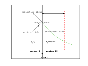
Our model is schematically shown in Fig.2, based on the total internal reflection (TIR) at the interface between a dielectric media (region ) and vacuum (region ). When the incident angle , the TIR will occur and the transmitted wave in the vacuum is the evanescent wave. We choose is a little larger than to make sure that almost all frequency components are totally reflected when the incidence is the slowly-varying quasi-monochromatic wave. An interferometer or a photon detector is set at distance from the interface so that the phase information and intensity change can be detected.
The time-dependent Maxwell equations are given by and , where and are the relative permittivity and the relative permeability, respectively, and . To obtain the concrete results, the system parameters are chosen as following, the incident angle , the refractive index of region , and the vacuum refractive index of region , where and are the real and imaginary index deviations of vacuum, because of VP processes caused by strong external field. If the incident probing light is a plane wave, the transmitted wave in the vacuum region can be generally written in the form , where and are the wave vectors parallel and perpendicular to the interface. For the evanescent wave, is described as:
| (1) |
The physical meaning of is very clear that the imaginary part corresponds to the exponential decay of the field, and the real part causes a phase change because of VP. The phase change at distance is
| (2) |
which could be measured by interferometersLawall2000 .
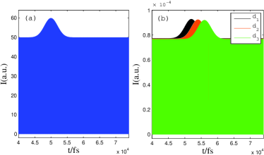
Besides the phase change , with the same model as shown in Fig.2, there is another way to detect the tiny by measuring the time delay of irradianceSuXuJB2003 fluctuation of the evanescent wave. The physical process can be explained in the following way. First, we suppose that the incident probing light is not a plane wave anymore, but with a slow intensity fluctuation which is proportional to the irradiance fluctuation, as shown in Fig.3(a), then the question is “What will happen for the evanescent wave in region II ?” From the strict Green’s function method with physical dissipation and dispersion, it is found that the fluctuation will propagate on the evanescent wave from the interface to far away, as shown in Fig.3(b). So, we can measure the time delay of the fluctuation propagation on the evanescent wave to detect the VP effect. The propagation speed of irradiance fluctuation can be obtained by the energy velocity which is defined as: , where is the averaged Poynting vector along direction, and is the local energy density of the electromagnetic wave. In our model, one can obtain the energy velocity as:
| (3) |
with , when the dissipation and dispersion are very weakgeneralcase . The physical meaning of can be understood as the “propagation” speed of electromagnetic wave irradiance fluctuation of the evanescent wave, which can be measured by the irradiance measurement technologySuXuJB2003 . Here we note that with tiny the expected energy velocity is much smaller than , and hence causality is not violated.
Hence, experimentally the time delay of the irradiance fluctuation at distance can be measured:
| (4) |
Since it is near field phenomenon, the detecting should be very near the interface. For the VP effect, since is extremely small, the “propagation” speed of the irradiance fluctuation is so slow that is long enough for detecting even in a very short distance , i.g. gets to peco-second level when the distance is one tenth of the wavelength .
Therefore, either the phase change or the time delay are very sensitive for , and the evanescent wave is a good candidate to probe the VP effect. Here, we note that the famous Kramers-Kronig relations, which shows the confinement of causality limit, still fit for QED vacuumRuffiniPR2009 . Hence, the direct observation of imaginary part of vacuum index also confirms the dispersive property of QED vacuum.
Next, we will quantitatively study the detect of QED VP by our methods. Supposing that an external homogeneous constant electric field , which is perpendicular to the plane and smaller than the Schwinger critical electric field , is applied to the vacuum (region ) only, as shown in Fig.2, then, the optical properties of the vacuum can be described by the Euler-Heisenberg Lagrangian RuffiniPR2009 ; GiesPRD2000 . Physically, the imaginary part of Euler-Heisenberg Lagrangian is related to the imaginary part of VP operator, and therefore corresponds to the electron-positron pair generation. This result of QED is well justified not only at zero-temperature but also at finite temperature casesGiesPRD2000 . Consequently, the vacuum refractive index can be deduced from the Lagrangian RuffiniPR2009 ; GiesPRD2000 ; HeylJPA1996 .
In our model, the contribution of the transmitted evanescent wave to is negligible, since its electric field is much weaker than , and furthermore, the external magnetic field is supposed to be zero, thus the vacuum refractive index is determined only by the external homogeneous constant electric field . We use and to refer the effective refractive index of vacuum when the electric field of probing light are parallel and perpendicular to the field , respectively. and can be obtained from the reference HeylJPA1996 :
| (5) |
and
| (6) |
where , and is the fine-structure constant. Therefore we have , for and when we solve the equations such as Eq.(1) in this letter.
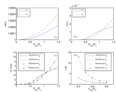
The parameters of our model in Fig.2 are chosen as following. The wavelength of probing light is , the dielectric constant in the region is , and the incident angle is , which is a little larger than critical angle of TIR, so that the field in vacuum is evanescent. The distance for the phase detecting is , while for the time delay detecting is , respectively. The QED theoretical results of real and imaginary part of and are shown in Fig.4(a) and Fig.4(b), respectively. Bring these results into Eq.(2) and Eq.(4), the phase change and the delayed time can be obtained, which are shown in Fig4(c) and Fig.4(d), respectively. Numerically, the phase change with plane wave incidence and the time delay of local amplitude maximum are calculated by Green’s function method, which are also shown in Fig.4(c) and Fig.4 (d). Comparing the analytical results from Eq.(2) and Eq.(3) and numerical results, we can find that they agree with each other very well.
Next, we will analyze the possibility to observe the VP effect in experimental conditions. The recent experimental advancesTESLATechnical have raised hopes that lasers may achieve fields just one or two orders of magnitude below the Schwinger critical field strength. In this case , from our numerical and analytical results in Fig.4, we can see the can get to order, which are in measuring limit of contemporary interferometer Lawall2000 . Very recently, it is supposed that the electric field could be effectively amplified 4 times larger by coherent constructive interference of laser beamsKingNP2010 . If can get to by this method, not only can be one order larger, but also the delay time can get to sub peco-second level and may be measured by contemporary photon detectors.
In conclusion, we have investigated the evanescent-mode-sensing methods to directly detect the QED VP based on evanescent wave. Theoretically, we clearly demonstrate that the imaginary part of QED vacuum index, caused by QED VP processes, can generate a phase and a time delay of irradiance fluctuation propagation on the evanescent wave. From Green’s function method, we obtain the numerical results of and , which agree with our analytical ones very well. The possibility to directly observe the effects of VP based on evanescent wave is discussed, and it is found that the required external electric field could be much smaller than the Schwinger critical field and maybe realizable in contemporary experiments. Our methods can also be used in other extremely sensitive detections.
Acknowledgement. This work is supported by the NSFC (Grant No. 11004212, 10704080, 60877067 and 60938004), the STCSM (Grant No. 08dj1400303 and 11ZR1443800).
References
- (1) D. Perkins, Introduction to high energy physics, 4th edition (Cambridge university press, Cambridge, 2000).
- (2) N. Ashcroft, N. Mermin, Solid State Physics (Harcourt College Publishers, New York, 1976) ; H. Bruus and K. Flensberg, Many-body quantum theory in condensed matter physics (Oxford university press, Oxford, 2004).
- (3) J. Goodman, Statistical Optics (John Wiley & Sons, Inc., New York, 1985).
- (4) R. Feynman, QED: the strange theory of light and matter (Princeton university press, Princeton, 1985).
- (5) R. Ruffini, G. Vereshchagin and S. Xue, Phys. Rep. 487, 1 (2010).
- (6) Y. Ding, A. Kaplan, Phys. Rev. Lett. 63, 2725 (1989).
- (7) B. King, A. Piazza and C. Keitel, Nat. photon. 4, 92 (2010).
- (8) H. Gies, Phys. Rev. D 61, 085021 (2000).
- (9) J. S Heyl and L. Hernquist, J. Phys. A: Math. Gen. 30, 6485 (1997).
- (10) R. G. Hunsperger, Integrated Optics: Theory and Technology (Springer-Verlag, New York, 1985).
- (11) B.Barwick, D.Flannigan, and A.H. Zewail, Nature 462, 902 (2009).
- (12) C. Carniglia and L. Mandel, J. Opt. Soc. Am. 61, 1035 (1971).
- (13) Z. Liu, Z. Liang, X. Jiang, X. Hu, X. Li, and J. Zi, Appl. Phys. Lett. 96, 113507 (2010).
- (14) J. Kong, Electromagnetic Wave Theory, Electromagnetic Wave Theory (Wiley-Interscience, New York, 1990).
- (15) J. Lawall and E. Kessler , Rev. Sci. Instrum. 71, 2669 (2000).
- (16) M. Bass, Handbook of Optics, Vol. II (McGraw-Hill, Inc., New York, 1995); W. Su, J. Li and N. Xu, J. Biotechnol. 105, 165 (2003).
- (17) In our model, for the general case, we can obtain: , where is the principle value of the argument, and .
- (18) T. Tajima, Eur. Phys. J. D 55, 519 (2009).