Spectroscopy of a fractional Josephson vortex molecule
Abstract
In long Josephson junctions with multiple discontinuities of the Josephson phase, fractional vortex molecules are spontaneously formed. At each discontinuity point a fractional Josephson vortex carrying a magnetic flux , Wb being the magnetic flux quantum, is pinned. Each vortex has an oscillatory eigenmode with a frequency that depends on and lies inside the plasma gap. We experimentally investigate the dependence of the eigenfrequencies of a two-vortex molecule on the distance between the vortices, on their topological charge and on the bias current applied to the Josephson junction. We find that with decreasing distance between vortices, a splitting of the eigenfrequencies occurs, that corresponds to the emergence of collective oscillatory modes of both vortices. We use a resonant microwave spectroscopy technique and find good agreement between experimental results and theoretical predictions.
pacs:
74.50.+r, 85.25.CpI Introduction
During the last decade the physics of fractional Josephson vortices has attracted a lot of attention.Kirtley et al. (1996, 1999); Smilde et al. (2002); Hilgenkamp et al. (2003); Goldobin et al. (2004a); Weides et al. (2006); Buckenmaier et al. (2007); Dewes et al. (2008) In contrast to the well known fluxons,Likharev (1986) fractional vortices carry the magnetic flux of . Here we focus on the fractional vortices that emerge at the discontinuities of the Josephson phaseBulaevskiĭ et al. (1978); Xu et al. (1995); Goldobin et al. (2002) in long Josephson junctions (LJJ) and disregard all other types, e.g., splintered vortices.Mints et al. (2002); Buzdin and Koshelev (2003); Goldobin et al. (2007) The phase discontinuity can be created by two tiny (compared to the Josephson penetration depth ) current injectors,Ustinov (2002); Goldobin et al. (2002); Goldobin et al. (2004a) so that , where is the current sent through the injectors.
A well known property of a long Josephson junction is the presence of a gap in the spectrum of electromagnetic waves (plasma waves) — the so-called plasma gap, which ranges from 0 to the plasma frequency . The value of is , where is the critical current density of the junction. In a LJJ with a fractional vortex pinned at the phase discontinuity, the vortex has an eigenfrequency which is situated within the plasma gap (localized mode with a wave number ). The value of depends on the topological charge of the vortex and the normalized bias current applied to the LJJ.Goldobin et al. (2005a)
The topological charge of a single fractional vortex in an infinite LJJ with a discontinuity of the phase is defined as , where is the Josephson phase, that is -discontinuous at one point. In simple words, is a continuous advance of the phase when one goes from to . Among all possible combinations of the phases at only two irreducible combinations are stableGoldobin et al. (2004b): the direct vortex with and a complementary vortex with . We assume that , otherwise the structure either cannot be constructed (not a solution of the sine-Gordon equation) or is unstable — it splits into one or several fluxons and a fractional vortex with .Goldobin et al. (2004b) For there is a smooth transition to the flat phase state of the LJJ, while for a(n) (anti)fluxon is formed. In contrast to the fractional vortex this fluxon is not pinned anymore and can move freely.Likharev (1986)
The eigenfrequency of a single fractional vortex as a function of and was already measured experimentallyBuckenmaier et al. (2007); Gaber et al. (2007) using microwave spectroscopy. Good agreement with numerical calculations was found.
Nowadays more complex fractional vortex systems, e.g. fractional vortex molecules consisting of two, three, etc. vortices can be created and studied experimentally.Dewes et al. (2008) In particular, two-vortex molecules with degenerate ground statesGoldobin et al. (2004b) are proposed as a candidate for a macroscopic qubit.Goldobin et al. (2005b) In such a molecule, the coupling between vortices results in shifting/splitting of their eigenfrequency,Goldobin et al. (2005a) very similar to the splitting of electronic energy levels in a real molecule when it is formed from atoms.
In this paper we experimentally investigate the eigenfrequencies in two types of symmetric two-vortex molecules: one with parallel (ferromagnetic) configuration and the topological charges and one with antiparallel (antiferromagnetic) order and the topological charges . We use a spectroscopic measurement techniqueBuckenmaier et al. (2007) to determine the eigenmodes of the molecule as a function of applied bias current and topological charges.
II Theory
The perturbed sine-Gordon equation, which describes the dynamics of the Josephson phase is given byGoldobin et al. (2002)
| (1) |
where subscripts and denote derivatives with respect to space and time and the step function describes the position of discontinuities. In the case of one discontinuity located at , , where is a Heaviside step function. In Eq. (1) the coordinate and time are normalized to the Josephson penetration depth and the inverse plasma frequency , respectively. is the dimensionless damping parameter, is the Stewart-McCumber parameter. The bias current density is normalized to the critical current density of the junction. To solve Eq. (1) numerically we introduce a new continuous phaseGoldobin et al. (2002) and solve the resulting smooth equation for .
The eigenfrequency of a single vortex with a topological charge in an unbiased () infinite LJJ without damping () is given by Goldobin et al. (2005a)
| (2) |
In case of no analytical expression has been found and therefore the eigenfrequency has to be calculated numerically. A good approximation to the numerical results is given by
| (3) |
where
| (4) |
is the depinning currentMalomed and Ustinov (2004); Goldobin et al. (2004c) of the vortex. For bias currents exceeding , the fractional vortex flips into its complementary partner, thereby emitting a fluxon.
If one considers two discontinuities with the same absolute value of that are situated at ( is the distance between the discontinuities) in an infinite LJJ, four irreducible vortex configurations are possible.Goldobin et al. (2004b) In the case of equal discontinuities, i.e. , there exists the symmetric parallel (ferromagnetically) ordered (FM) vortex molecule with and the asymmetric antiparallel (antiferromagnetically) ordered (AFM) vortex molecule with . For discontinuities of different signs, i.e. , one gets either the symmetric antiparallel molecule with or the asymmetric parallel vortex molecule with .
In the experiments described below we use annular LJJsDavidson et al. (1985) with two discontinuities at a distance from each other, where is the mean circumference of the junction normalized to . There are certain advantages of this particular geometry. First, due to a particular shape of the electrodes, annular junctions have intrinsically a much more homogeneous bias current density than linear LJJs,Martucciello et al. (1998) which is important to measure . Second, any real LJJ has a finite length, which results in a somewhat modified phase profile and eigenfrequency spectrum of the vortex molecules. The boundary conditions of the junction thereby impose an additional level of symmetry/ordering on the molecule. In an annulus this additional symmetry is always the same as the internal configuration of the molecule, FM or AFM.111The phase profile of a two-vortex molecule in a finite LJJ can be constructed by employing vortex images using the boundaries of the junction as mirrors.Goldobin et al. (2004a) In linear geometry the phase resembles a piece of length of an infinite chain of AFM ordered vortex pairs, even for a FM ordered molecule. Annular geometry, however, results in a FM order of vortex pairs, thereby conserving the molecules inner configuration.
In an annular junction each vortex has the same neighbor on both sides (right and left) so that magnetic field profiles and eigenfrequencies are somewhat different from the results obtained earlier for an infinite LJJ.Goldobin et al. (2004b) This is especially true for short JJs. In principle, there are many eigenmodes enumerated according to their frequency. In the following we use to denote the eigenfrequency of the vortex in-phase oscillations, while denotes the oscillation mode with a phase shift of . They correspond to the two lowest eigenmodes and , i.e. or . Depending on the configuration of the molecule can be larger or smaller than . In general, the eigenfrequencies of a molecule can only be calculated numerically.Goldobin and Wallraff (2006) Due to the vast number of possible molecule configurations we, in the following, limit ourselves to the symmetric configurations and discuss them in more detail.
II.1 Parallel (FM) molecule
The magnetic field of a molecule consisting of two parallel ordered vortices pinned at discontinuities is exemplarily shown in Fig. 1(a) for an annular LJJ of length . The vortex distance is half of the junction length. No bias current is applied.
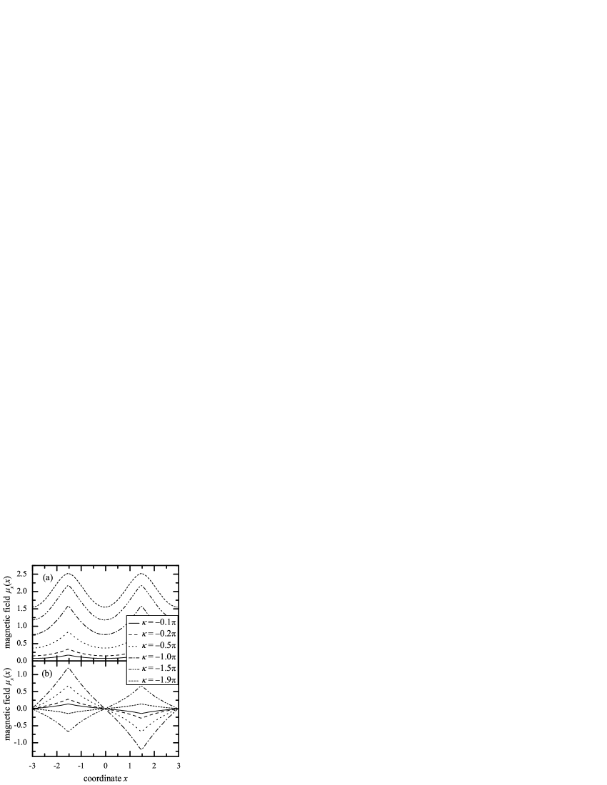
Then, the FM configuration is stable for and for all lengths due to annular boundary conditions and , cf. Refs. Goldobin et al., 2005a and Goldobin et al., 2004b for more general cases. For , a single direct vortex with is not stable anymore. Instead, at each discontinuity a(n) (anti)fluxon and a -vortex (all of the same polarity)Goldobin et al. (2004b) is formed.
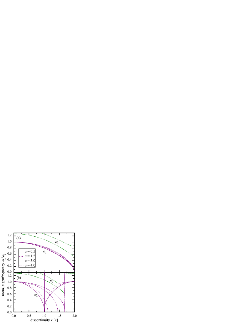
The eigenfrequencies of a FM ordered molecule are shown in Fig. 2(a) as a function of for different vortex distances.
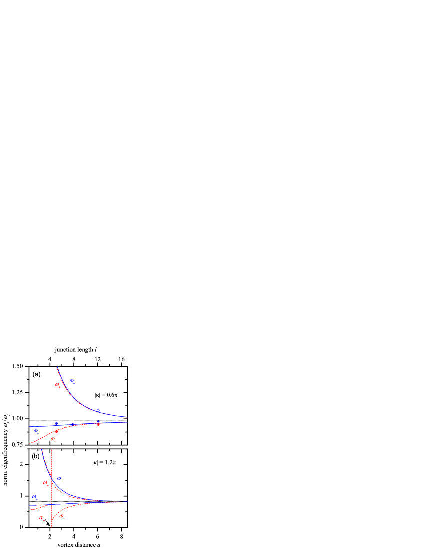
Here, . The dependence of is shown in Fig. 3 for two molecules with specific values of the discontinuities . For comparison, the eigenfrequency of a single vortex in an infinitely long JJ is also shown. As can be seen the frequency splitting increases for smaller (larger coupling). However, the divergence of the out-of-phase mode for is exclusively related to the fact, that also and therefore for .
II.2 Antiparallel (AFM) molecule
Figure 1(b) shows the magnetic field for the antiparallel molecule pinned at discontinuities in an annular LJJ of . In contrast to the parallel configuration there exists a critical value (), above which the vortices are not stable anymore: after exchanging one the -molecule turns into a complementary one . The value of depends on and can in general only be calculated numerically. For an AFM molecule in an infinitely long JJ was calculated in Ref. Goldobin et al., 2004b. Note that for both states and are stable and that for these solutions have different energies.
The eigenfrequencies of the two lowest modes of the antiparallel configuration are shown in Fig. 2(b). The vertical lines describe the critical discontinuity for different vortex distances . In contrast to the parallel configuration, here .
The dependence of the eigenfrequencies of two antiparallel vortices for fixed values as a function of the distance is shown in Fig. 3. As with the parallel configuration the frequency splitting increases when decreases. One has to recognize, that for the critical vortex distance is . Therefore, the vortex state becomes unstable at and the frequency . For , correspond to the complementary state , which is stable for all . In comparison to the lowest eigenfrequency of the parallel configuration, this mode has a smaller frequency and this difference increases as .
For a biased molecule () the approximation (3) can also be used to estimate .
III Experiments
For experiments we used underdamped long Nb-AlOx-Nb annular tunnel junctions fabricated using standard trilayer technology.Kaiser et al. (2011) Each JJ was equipped with two pairs of current injectors as shown in Fig. 4.
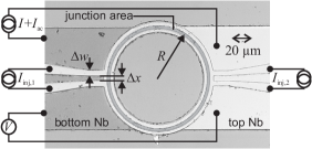
Note that injector pairs are placed opposite to each other and directly on top/below the bias electrodes of the junction, as earlier measurements showed this layout to give best agreement of the critical current dependence with theory, i.e. Eq. (4). As the JJs have been fabricated in an overlap geometry, their static and dynamic properties are modified by the overlap region of top and bottom electrode, the so-called idle region.Caputo et al. (1994, 1996, 1999); Lee (1991); Lee and Barfknecht (1992); Flytzanis et al. (2000) Idle region effects can be taken into account by a renormalization of the junction length, i.e. by introducing an effective Josephson penetration depth . However, we find that the usual correctionCaputo et al. (1999) overestimates the idle region effect. Table 1 summarizes the properties of the measured junctions, listing Josephson penetration depths and normalized junction lengths, with and without idle region corrections, as well as the normalized lengths we found to give best agreement with theory.
| # | ||||||||
| [m] | [A/cm2] | [m] | [m] | [GHz] | ||||
| 1 | 30 | 112 | 35.7 | 5.3 | 41.4 | 4.6 | 5.1 | 45.1 |
| 2 | 50 | 90 | 39.8 | 7.9 | 46.1 | 6.8 | 7.8 | 44 |
| 3 | 80 | 77 | 40.9 | 12.3 | 43.7 | 11.4 | 12.1 | 36 |
The measurements shown in this paper have been performed at with the resonant vortex excitation technique already used to determine the eigenfrequency of a single fractional vortex.Buckenmaier et al. (2007) In brief, we continuously apply microwaves with fixed frequency and fixed power to the junction while ramping up the bias current . As decreases with increasing , cf. Eq. (3), the resonance condition is achieved for some . Then, depending on applied microwave power and the internal damping of the junction, the vortex molecule may flip and switch the junction into its resistive state.Fistul and Ustinov (2000) If, however, the junction remains in the zero-voltage state it switches to the non-zero voltage state by means of thermal escape when the bias approaches the fluctuation-free critical current . By repeatedly measuring the switching current and systematically scanning microwave power and frequency we can map out the resonances corresponding to the eigenmodes of the molecule. As the JJ itself is a non-linear oscillator, resonances shift towards lower frequencies with increasing microwave power.Likharev (1986); Fistul and Ustinov (2000); Grønbech-Jensen et al. (2004); Grønbech-Jensen and Cirillo (2004); Blackburn et al. (2010) This is especially relevant at small where the energy barrier between the zero and the non-zero voltage state is still large and high microwave power is necessary for switching. We therefore determine from the measurements with the lowest power to keep non-linear effects to a minimum.
Before spectroscopy was performed, injectors were calibrated. For this we first measured the critical current of the junction as a function of the current through each injector pair and individually. From Eq. (4) and we then determined the injector currents necessary to create a discontinuity of , where have the cusp like first minima. Figure 5(a) and (b) show the measured dependences of sample 1, as well as the fitted theoretical curves.
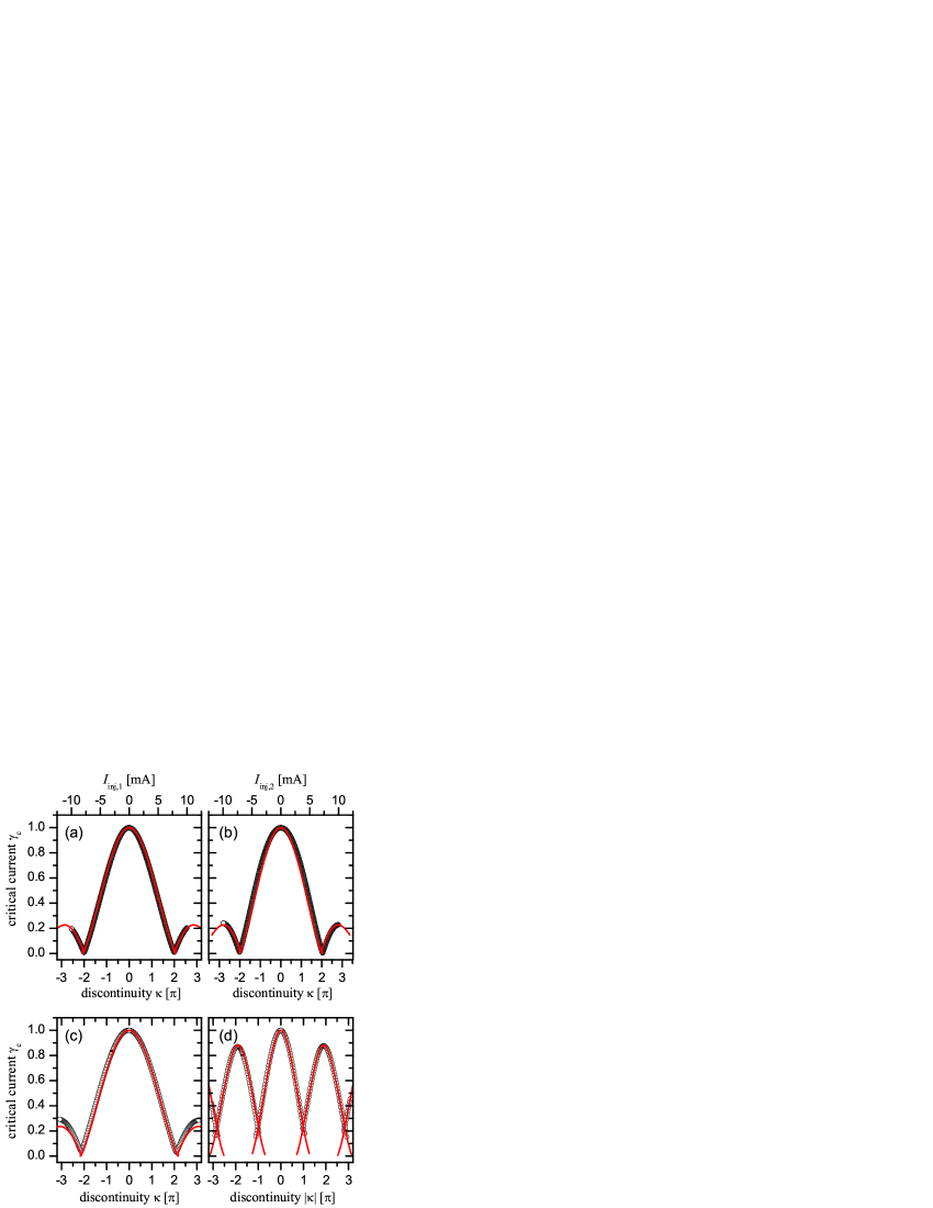
Although both injector pairs have nominally the same width and distance, the are usually somewhat different. In sample 3 the inequality was introduced intentionally, as we deliberately cut the top wiring layer between the injectors to increase the coupling of to the junction. However, in samples 1 and 2, both injector pairs are identical by design. Here, we believe, the deviations are due to lithographical inaccuracy and different thicknesses of the top and bottom Nb layer. To create symmetric vortex molecules we henceforth applied the injector currents simultaneously.
Figure 5(c) shows the measured and the numerically calculated dependence of a symmetric FM vortex molecule pinned at discontinuities. As can be seen there is a good agreement between experiment and theory. Note that looks qualitatively similar to for a single vortex,Malomed and Ustinov (2004) yet the first minimum positions are slightly different: of a symmetric FM vortex molecule in an annular JJ with a finite width , of injector pairs corresponds to a value, which is slightly larger than .
The curve for the AFM molecule is depicted in Fig. 5(d). Again, experimental data and numerical calculations are in good agreement. In contrast to the FM configuration, here the -minima correspond to instead of , cf. Eq. (4). Note that the curve is identical to the dependence of a linear LJJ of length with a single central vortex.Gaber et al. (2005) As already mentioned in Sec. II.2, the AFM molecule exhibits regions of bistability of the direct and the complementary vortex states around . Between the critical current of both vortex states can be traced out,Dewes et al. (2008) see Fig. 5(d). In AFM configuration the pattern sensitively depends on junction length as well as on injector sizeGaber et al. (2005): For infinitesimally small injectors, the is periodic with maxima at and minima at . For finite size injectors, however, this is not the case: and the minimum positions shift to . In the FM case basically only depends on injector size — the shape of the curve does not change. By carefully comparing the curves of the AFM configuration with numerical simulations we obtained the normalized junction length , see Tab. 1, which we used for the subsequent calculation of eigenfrequencies.
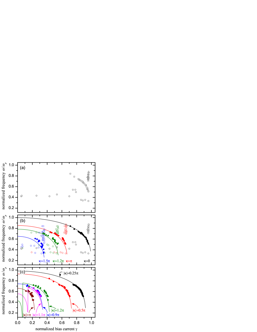
After calibration of injectors we spectroscopically mapped out the well-known dependence of the plasma frequency on applied bias current. Figure 6(a) shows exemplarily the results of the plasma frequency scan of sample 1. All measured resonance peak positions are plotted. Beside the desired plasma resonance (squares), additional resonances were observed. They do not correspond to a sub- or a superharmonic excitation of the plasma resonance, but can be subsumized into two groups. One set of resonances (triangles) occurs at high frequencies and close to the critical current of the junction. These resonances are most likely the result of a microwave enhanced thermal escape. The second group of resonances (circles) seem to be erratically distributed over the full bias current range. Yet, a comparison with other spectroscopic measurements, e.g. see Fig. 6(b), shows that they appear in rather small frequency bands, where the coupling of the microwave current to the junction is exceptionally high. We therefore believe that they are the result of a parasitic coupling of the junction to cavity modes of the sample box and the bias circuitry. Note, that in contrast to a typical spectroscopic measurement of the plasma frequency or the eigenfrequency of a single fractional vortex, e.g. see Ref. Buckenmaier et al., 2007, we did not simply trace out the desired resonance curve by optimizing the measured frequency range and the applied microwave power. Instead, we systematically scanned over a large microwave power and frequency range to ensure, that no resonance is missed. Evidently, this measurement technique also reveals parasitic resonances, which are not of interest and must be removed in a manual post-selection process. From the measured plasma resonance (squares) we extracted and the fluctuation-free critical current of the junction, which then served as a reference for the following measurements on vortex molecules. is the junction radius, the junction width. We also determined from measurements of the zero field stepsFulton and Dynes (1973) on the current-voltage characteristics of the junction. After corrections due to idle region effectsLee (1991); Lee and Barfknecht (1992); Caputo et al. (1996) we typically find both values in agreement by better than 90%.
Figure 6(b) shows all measured resonance peak positions of a set of FM ordered vortex molecules in sample 1. Also plotted are the corresponding numerically calculated dependences. As sample 1 is rather short (), is much larger than the highest frequency of our rf-generator and could therefore not be measured. As already discussed for the plasma frequency measurement, we partitioned the data — eigenmode resonances are plotted with full symbols, whereas open symbols correspond to parasitic resonances. Beside a certain ambiguity of the data selection process, a good agreement with theory can clearly be seen.

The measurement results of the more interesting AFM case are shown in Fig. 6(c). Here, injector currents were reset after each switching current measurement to ensure a well defined initial molecule state. Also, only eigenmode resonances are plotted. Again, there is a good agreement between experiment and theory. It is interesting to note, that for almost no signature of the direct vortex state can be seen. Instead, the measured resonances correspond to the complementary state , which has a higher eigenfrequency . As mentioned in Sec. II.2, for both the direct and the complementary molecule state are stable, yet have different energies and different critical currents, cf. Fig. 5(d). In case of sample 1, . When a bias current is applied that exceeds of the direct state, the molecule flips into the complementary state by exchange of one fluxon between the vortices. In contrast to the FM case however, here this transition is not automatically followed by the switching of the junction into a non-zero voltage state. So, as the experimental data indicates, already for the vortex flipping usually remains undetected and only the more stable complementary state is measured.
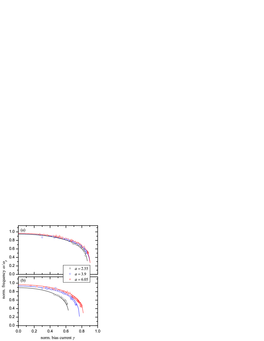
Using Eq. (3) we fitted the measured resonance peaks (full symbols) in Fig. 6 leaving and at zero bias as free parameters. Figure 7 shows the obtained values of and compares them with theory. As expected from Fig. 6 we find very good agreement. As the finite injector size influences the eigenfrequency spectrum, Fig. 7 also shows the theoretical dependences of for ideal discontinuities. Clearly, only for large discontinuities, i.e. , differences become significant.
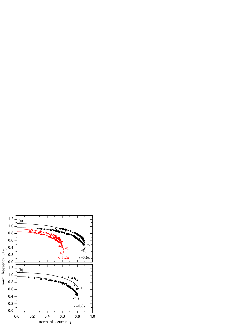
In sample 1 only the lowest eigenmode could be investigated due to limitations of our rf-generator. To experimentally investigate higher eigenmodes we measured sample 3, which is the longest JJ and also has the lowest plasma frequency. Figures 8(a) and (b) show the observed resonance peak positions of the measured FM and AFM configurations. Parasitic resonances are not plotted. Interestingly, in the FM configuration both eigenmodes can clearly be seen, yet only the lowest mode is present in the AFM state. Further measurements confirmed, that for all symmetric FM states we selected, the observed resonances clearly showed two modes coinciding with the theoretical dependence of , yet only a single mode for the AFM states. Even more surprising, measurements on two other samples of proper length (not shown) revealed no trace of , neither in AFM nor the FM state, indicating some general problem with the excitation of higher modes — sample 3 being the exception. So far it is unclear to us, whether this behavior is owed to the particular way we apply microwaves to the JJ, i.e. by capacitive coupling to the bias line, or to a more fundamental reason.
As has been shown in Fig. 3 coupling between the vortices in a molecule can be adjusted by changing the distance between them — the smaller is the distance, the larger is the coupling (frequency splitting). Clearly, compared to the FM configuration, the deviation of the frequency of the lowest mode from the single vortex frequency (2) is much more pronounced in the AFM case. The configuration related, different dependence of on can also be seen in Fig. 9, where we directly compare of the FM and AFM ordered molecules and for three different vortex distances . As expected, the eigenfrequency of the AFM state is much more sensitive to than of the FM state. Finally, we used Eq. (3) to obtain at from measurements, which are shown in Fig. 3.
IV Conclusions
We experimentally investigated the interaction of fractional Josephson vortices in a symmetric two-vortex molecule by measuring the oscillatory eigenmodes of the molecule spectroscopically. We observe a splitting of the single vortex eigenmode due to vortex-vortex coupling. The emerging molecule modes correspond to an in-phase and an out-of-phase oscillation of the individual vortices. The measured dependence of the eigenfrequencies of the molecule on applied bias current, topological charge of the vortices and vortex ordering are in good agreement with numerical calculations. We find that with decreasing vortex distance coupling and frequency splitting increases. Depending on the configuration of the molecule, i.e. parallel or antiparallel vortex order, spectra show significantly different behavior, which can, in principle, be used to identify an unknown vortex state.
Acknowledgements.
This work was supported by the Deutsche Forschungsgemeinschaft via SFB/TRR-21 and the DFG Center of Functional Nanostructures (project B1.5). U. K. gratefully acknowledges support by the Bischöfliche Studienförderung Cusanuswerk, K. B. and H. S. by the Evangelisches Studienwerk e.V. Villigst.References
- Kirtley et al. (1996) J. R. Kirtley, C. C. Tsuei, M. Rupp, J. Z. Sun, L. S. Yu-Jahnes, A. Gupta, M. B. Ketchen, K. A. Moler, and M. Bhushan, Phys. Rev. Lett. 76, 1336 (1996).
- Kirtley et al. (1999) J. R. Kirtley, C. C. Tsuei, and K. A. Moler, Science 285, 1373 (1999).
- Smilde et al. (2002) H.-J. H. Smilde, Ariando, D. H. A. Blank, G. J. Gerritsma, H. Hilgenkamp, and H. Rogalla, Phys. Rev. Lett. 88, 057004 (2002), .
- Hilgenkamp et al. (2003) H. Hilgenkamp, Ariando, H.-J. H. Smilde, D. H. A. Blank, G. Rijnders, H. Rogalla, J. R. Kirtley, and C. C. Tsuei, Nature 422, 50 (2003).
- Goldobin et al. (2004a) E. Goldobin, A. Sterck, T. Gaber, D. Koelle, and R. Kleiner, Phys. Rev. Lett. 92, 057005 (2004a).
- Weides et al. (2006) M. Weides, M. Kemmler, H. Kohlstedt, R. Waser, D. Koelle, R. Kleiner, and E. Goldobin, Phys. Rev. Lett. 97, 247001 (2006).
- Buckenmaier et al. (2007) K. Buckenmaier, T. Gaber, M. Siegel, D. Koelle, R. Kleiner, and E. Goldobin, Phys. Rev. Lett. 98, 117006 (2007).
- Dewes et al. (2008) A. Dewes, T. Gaber, D. Koelle, R. Kleiner, and E. Goldobin, Phys. Rev. Lett. 101, 247001 (2008).
- Likharev (1986) K. K. Likharev, Dynamics of Josephson Junctions and circuits (Gordon and Breach Publishers, 1986).
- Bulaevskiĭ et al. (1978) L. N. Bulaevskiĭ, V. V. Kuziĭ, and A. A. Sobyanin, Solid Stat. Comm. 25, 1053 (1978).
- Xu et al. (1995) J. H. Xu, J. H. Miller, and C. S. Ting, Phys. Rev. B 51, 11958 (1995).
- Goldobin et al. (2002) E. Goldobin, D. Koelle, and R. Kleiner, Phys. Rev. B 66, 100508 (2002).
- Mints et al. (2002) R. G. Mints, I. Papiashvili, J. R. Kirtley, H. Hilgenkamp, G. Hammerl, and J. Mannhart, Phys. Rev. Lett. 89, 067004 (2002).
- Buzdin and Koshelev (2003) A. Buzdin and A. E. Koshelev, Phys. Rev. B 67, 220504 (2003).
- Goldobin et al. (2007) E. Goldobin, D. Koelle, R. Kleiner, and A. Buzdin, Phys. Rev. B 76, 224523 (2007).
- Ustinov (2002) A. V. Ustinov, Appl. Phys. Lett. 80, 3153 (2002).
- Goldobin et al. (2005a) E. Goldobin, H. Susanto, D. Koelle, R. Kleiner, and S. A. van Gils, Phys. Rev. B 71, 104518 (2005a).
- Goldobin et al. (2004b) E. Goldobin, D. Koelle, and R. Kleiner, Phys. Rev. B 70, 174519 (2004b).
- Gaber et al. (2007) T. Gaber, K. Buckenmaier, D. Koelle, R. Kleiner, and E. Goldobin, Appl. Phys. A 89, 587 (2007).
- Goldobin et al. (2005b) E. Goldobin, K. Vogel, O. Crasser, R. Walser, W. P. Schleich, D. Koelle, and R. Kleiner, Phys. Rev. B 72, 054527 (2005b).
- Malomed and Ustinov (2004) B. A. Malomed and A. V. Ustinov, Phys. Rev. B 69, 064502 (2004).
- Goldobin et al. (2004c) E. Goldobin, N. Stefanakis, D. Koelle, and R. Kleiner, Phys. Rev. B 70, 94520 (2004c).
- Davidson et al. (1985) A. Davidson, B. Dueholm, B. Kryger, and N. F. Pedersen, Phys. Rev. Lett. 55, 2059 (1985).
- Martucciello et al. (1998) N. Martucciello, J. Mygind, V. P. Koshelets, A. V. Shchukin, L. V. Filippenko, and R. Monaco, Phys. Rev. B 57, 5444 (1998).
- Goldobin and Wallraff (2006) E. Goldobin and A. Wallraff, StkJJ — User’s Reference, http://www.geocities.com/SiliconValley/Heights/7318/StkJJ.htm (2006).
- Kaiser et al. (2011) C. Kaiser, J. M. Meckbach, K. S. Ilin, J. Lisenfeld, R. Schäfer, A. V. Ustinov, and M. Siegel, Supercond. Sci. Technol. 24, 035005 (2011).
- Caputo et al. (1994) J. G. Caputo, N. Flytzanis, and M. Devoret, Phys. Rev. B 50, 6471 (1994).
- Caputo et al. (1996) J. G. Caputo, N. Flytzanis, and E. Vavalis, Int. J. Mod. Phys. C 7, 191 (1996).
- Caputo et al. (1999) J. G. Caputo, N. Flytzanis, V. Kurin, N. Lazarides, and E. Vavalis, J. Appl. Phys. 85, 7291 (1999).
- Lee (1991) G. Lee, IEEE Trans. Appl. Supercond. 1, 121 (1991), ISSN 1051-8223.
- Lee and Barfknecht (1992) G. S. Lee and A. T. Barfknecht, IEEE Trans. Appl. Supercond. 2, 67 (1992), ISSN 1051-8223.
- Flytzanis et al. (2000) N. Flytzanis, N. Lazarides, A. Chiginev, V. Kurin, and J. G. Caputo, J. Appl. Phys. 88, 4201 (2000).
- Fistul and Ustinov (2000) M. V. Fistul and A. V. Ustinov, Phys. Rev. B 63, 024508 (2000).
- Grønbech-Jensen et al. (2004) N. Grønbech-Jensen, M. G. Castellano, F. Chiarello, M. Cirillo, C. Cosmelli, L. V. Filippenko, R. Russo, and G. Torrioli, Phys. Rev. Lett. 93, 107002 (2004).
- Grønbech-Jensen and Cirillo (2004) N. Grønbech-Jensen and M. Cirillo, Phys. Rev. B 70, 214507 (2004).
- Blackburn et al. (2010) J. A. Blackburn, M. Cirillo, and N. Grønbech-Jensen, Phys. Lett. A 374, 2827 (2010).
- Gaber et al. (2005) T. Gaber, E. Goldobin, A. Sterck, R. Kleiner, D. Koelle, M. Siegel, and M. Neuhaus, Phys. Rev. B 72, 054522 (2005).
- Fulton and Dynes (1973) T. A. Fulton and R. C. Dynes, Solid State Commun. 12, 57 (1973).